-- 1 --
CPD-200ES
MICROFILM
SERVICE MANUAL
TRINITRON® COLOR COMPUTER DISPLAY
CPD-200ES
CPD-200ES
S. Hemisphere Model
Equator Model
Chassis No.SCC-L16B-A
X2F CHASSIS
SPECIFICATIONS
Picture Tube
Video image area
Logical resolution
Physical resolution
Standard image area
Deflection frequency
AC input voltage / current
Dimensions
Mass
Approx. 312 x 234 mm (w/h)
(12.3 x 9.3 inches)
Horizontal: 31 to 70 KHz
Vertical: 50 to 120 Hz
100 to 120 V, 50-60 Hz,1.8 A (max.)
220 to 240 V, 50-60 Hz, 1.0 A
406 x 431.5 x 420 mm (w/h/d)
(16
x
17
x
16.5
inches)
Approx. 19.0 kg (41 lb. 13 oz.)
Design and specifications are subject to change without notice.
0.26 mm aperture grill pitch
17 inches measured diagonally
90-degree deflection
(15.9" maximum viewing image)
Approx. 327 x 241 mm (w/h)
(12.9 x 9.5 inches)
Horizontal: Max. 1280 dots
Vertical: Max. 1024 lines
Horizontal: Max. 1024 dots
Vertical:
Max.
768
lines
-- 2 --
CPD-200ES
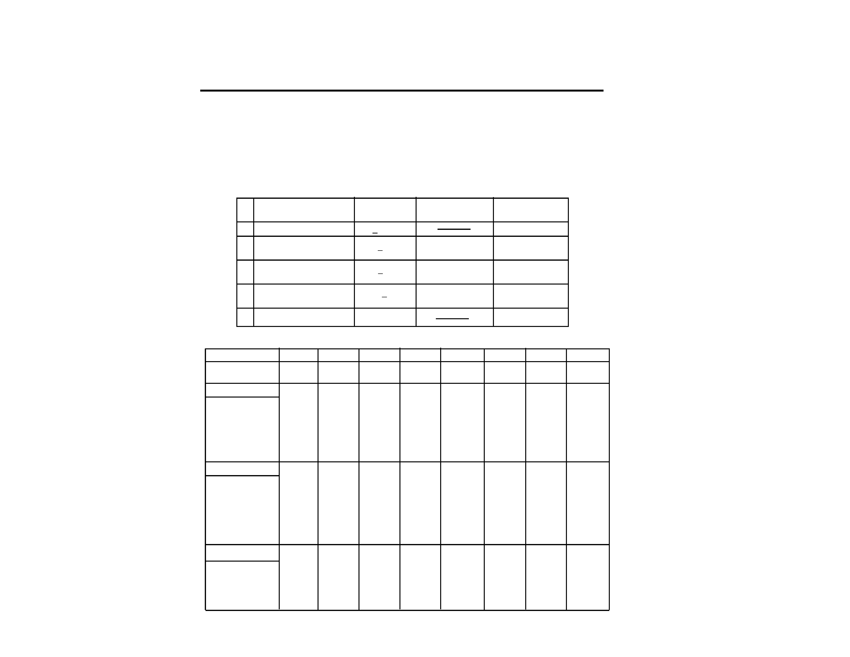
POWER SAVING FUNCTION
This monitor meets the power saving guidelines set
by the EPA Energy Star Program as well as the more
stringent TC092 guidelines (NUTEK). It is capable of
reduced power consumption when used with a com-
puter equipped with Display Power Management Sig-
naling (DPMS). By sensing the absence of the sync
signal coming from the computer, it will reduce the
power consumption as follows:
The Power Saving function will automati-
cally put the monitor into Active-off state
if the power switch is turned on without
any video signal input. Once the horizon-
tal and vertical syncs are sensed, the moni-
tor will automatically return to its Normal
operation state.
CAUTION:
Mode
1
2
3
4
5
6
7
8
<8 W
approx. 10 sec.
orange on
0 W
off
State
Power
Required
u Power indicator
consumption
resumption time
Active-off
(2nd step of power saving)
Suspend
(1st step of power saving)
1
2
3
4
5
Power - Off
Active-off
(3rd step of power saving)
<15 W
approx. 3 sec.
Normal Operation
<110 W
green on
<15 W
approx. 10 sec.
orange and green
flashes alternately
orange and green
flashes alternately
Resolution(H x V)
Dot Clock(MHz)
Hor. Freq. (kHz)
H-Total
H-Blanking
H-Front Porch
H-Sync.
H-Back Porch
H-Active
(
µsec)
Ver. Freq. (Hz)
V-Total
V-Blanking
V-Front Porch
V-Sync.
V-Back Porch
V-Active
(lines)
Horizontal
Vertical
Sync.
INT(G)
EXT (H/V)/POLARITY
EXT (CS)/POLARITY
INT/NON INT
TIMING SPECIFICATION
640 x 480
25.175
31.469
31.778
6.356
0.636
3.813
1.907
25.422
59.940
525
45
10
2
33
480
640 x 480
36.000
43.269
23.111
5.333
1.556
1.556
2.222
17.778
85.008
509
29
1
3
25
480
800 x 600
49.500
46.875
21.333
5.172
0.323
1.616
3.232
16.162
75.000
625
25
1
3
21
600
800 x 600
56.250
53.674
18.631
4.409
0.569
1.138
2.702
14.222
85.061
631
31
1
3
27
600
832 x 624
57.283
49.725
20.111
5.586
0.559
1.117
3.910
14.524
74.550
667
43
1
3
39
624
1024 x 768
78.750
60.023
16.660
3.657
0.203
1.219
2.235
13.003
75.029
800
32
1
3
28
768
NO
YES
-/-
NO
NON INT
NO
YES
-/-
NO
NON INT
NO
YES
+/+
NO
NON INT
NO
YES
+/+
NO
NON INT
NO
YES -/-
NO
NON INT
NO
YES
+/+
NO
NON INT
1024 x 768
94.500
68.677
14.561
3.725
0.508
1.016
2.201
10.836
84.997
808
40
1
3
36
768
NO
YES
+/+
NO
NON INT
1280 x 1024
108.000
63.981
15.630
3.778
0.444
1.037
2.296
11.852
60.020
1066
42
1
3
38
1024
NO
YES
+/+
NO
NON INT
-- 3 --
CPD-200ES
SAFETY CHECK-OUT
(US Model only)
After correcting the original service problem, perform
the following safety checks before releasing the set to the
customer:
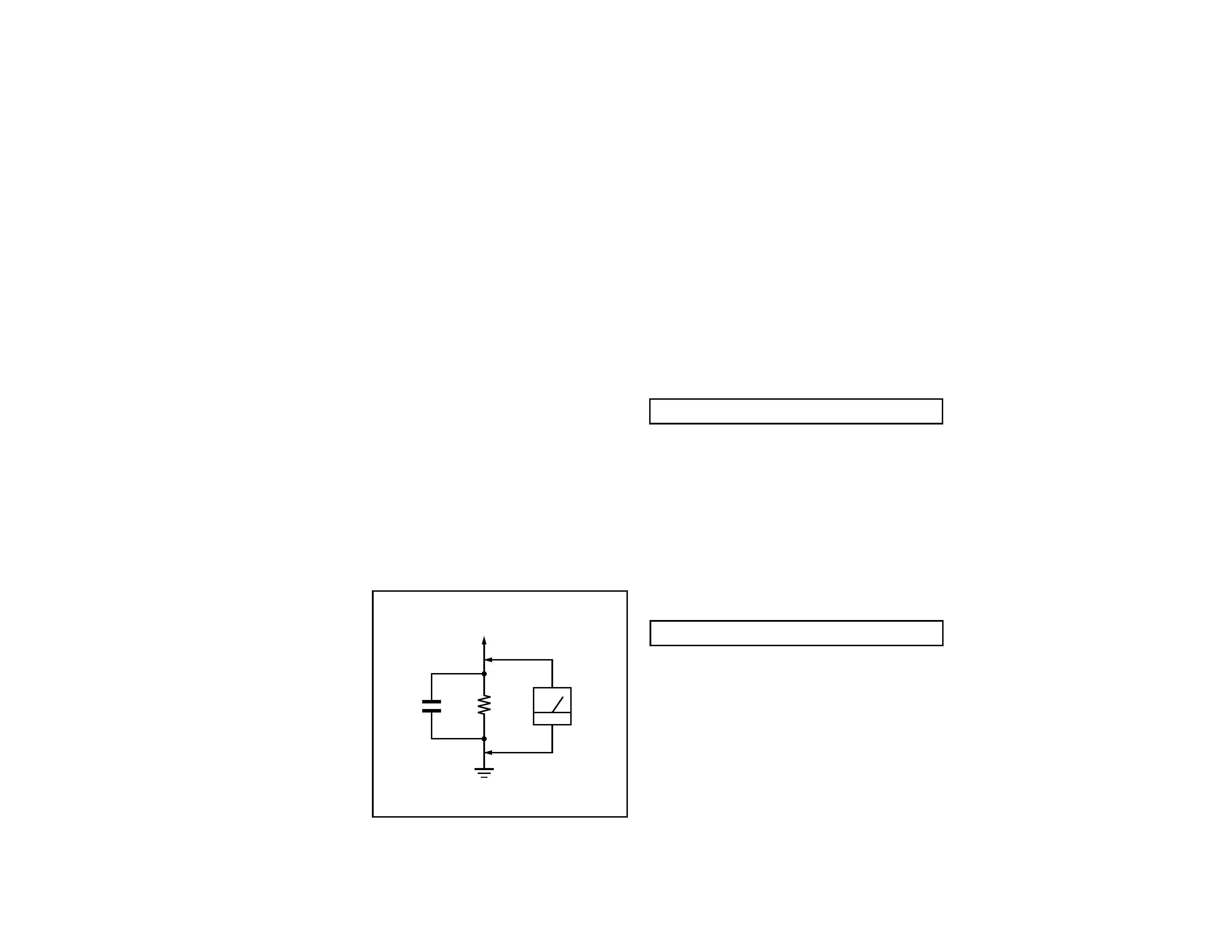
LEAKAGE TEST
The AC leakage from any exposed metal part to earth ground
and from all exposed metal parts to any exposed metal part having
a return to chassis, must not exceed 0.5 mA (500 microampere).
Leakage current can be measured by any one of three methods.
WARNING!!
WARNING!!
WARNING!!
WARNING!!
WARNING!!
NEVER TURN ON THE POWER IN A CONDITION IN WHICH THE
DEGAUSS COIL HAS BEEN REMOVED.
SAFETY-RELATED COMPONENT WARNING!!
COMPONENTS IDENTIFIED BY SHADING AND MARK
¡ ON
THE SCHEMATIC DIAGRAMS, EXPLODED VIEWS AND IN THE
PARTS LIST ARE CRITICAL FOR SAFE OPERATION. REPLACE
THESE COMPONENTS WITH SONY PARTS WHOSE PART
NUMBERS APPEAR AS SHOWN IN THIS MANUAL OR IN
SUPPLEMENTS PUBLISHED BY SONY. CIRCUIT ADJUSTMENTS
THAT ARE CRITICAL FOR SAFE OPERATION ARE IDENTIFIED
IN THIS MANUAL. FOLLOW THESE PROCEDURES WHENEVER
CRITICAL COMPONENTS ARE REPLACED OR IMPROPER
OPERATION IS SUSPECTED.
AVERTISSEMENT!!
NE JAMAIS METTRE SOUS TENSION OUAND LA BOBINE DE
DEMAGNETISATION EST ENLEVEE.
ATTENTION AUX COMPOSANTS RELATIFS A LA
SECURITE!!
LES COMPOSANTS IDENTIFIES PAR UNE TRAME ET PAR UNE
MARQUE
¡ SUR LES SCHEMAS DE PRINCIPE, LES VUES
EXPLOSEES ET LES LISTES DE PIECES SONT D'UNE
IMPORTANCE
CRITIQUE
POUR
LA
SECURITE
DU
FONCTIONNEMENT. NE LES REMPLACER QUE PAR DES
COMPOSANTS SONY DONT LE NUMERO DE PIECE EST
INDIQUE DANS LE PRESENT MANUEL OU DANS DES SUPPLE-
MENTS PUBLIES PAR SONY. LES REGLAGES DE CIRCUIT
DONT
L'IMPORTANCE
EST
CRITIQUE
POUR
LA
SECURITE DU FONCTIONNEMENT SONT IDENTIFIES DANS
LE PRESENT MANUEL. SUIVRE CES PROCEDURES LORS DE
CHAQUE REMPLACEMENT DE COMPOSANTS CRITIQUES, OU
LORSQU'UN MAUVAIS FONTIONNEMENT SUSPECTE.
1. Check the area of your repair for unsoldered or
poorly-soldered connections. Check the entire board
surface
for
solder
splashes
and
bridges.
2. Check the interboard wiring to ensure that no wires
are "pinched" or contact high-wattage resistors.
3. Check that all control knobs, shields, covers, ground
straps, and mounting hardware have been replaced.
Be absolutely certain that you have replaced all the
insulators.
4. Look for unauthorized r eplacement parts,
particularly transistors, that were installed during
a previous repair. Point them out to the customer
and recommend their replacement.
5. Look for parts which, though functioning, show
obvious signs of deterioration. Point them out to
the customer and recommend their replacement.
6. Check the line cords for cracks and abrasion.
Recommend the replacement of any such line cord
to the customer.
7. Check the B+ and HV to see if they are specified
values. Make sure your instruments are accurate;
be suspicious of your HV meter if sets always have
low HV.
8. Check the antenna terminals, metal trim,
"metallized" knobs, screws, and all other exposed
metal parts for AC Leakage. Check leakage as
described below.
1. A commercial leakage tester, such as the Simpson 229 or
RCA WT-540A. Follow the manufacturers' instructions to
use these instructions.
2. A battery-operated AC milliammeter. The Data Precision
245 digital multimeter is suitable for this job.
3. Measuring the voltage drop across a resistor by means of
a VOM or battery-operated AC voltmeter. The "limit"
indication is 0.75 V, so analog meters must have an accurate
low voltage scale. The Simpson's 250 and Sanwa
SH-63Trd are examples of passive VOMs that are suitable.
Nearly all battery operated digital multimeters that have a
2V AC range are suitable. (See Fig. A)
1.5 k
0.15 µF
AC
Voltmeter
(0.75 V)
To Exposed Metal
Parts on Set
Earth Ground
Fig. A. Using an AC voltmeter to check AC leakage.

-- 4 --
CPD-200ES
TABLE OF CONTENTS
Section
Title
Page
1. GENERAL ................................................................................... 5
2. DISASSEMBLY
2-1. Cabinet Removal ............................................................8
2-2. Service Position ...............................................................8
2-3. D Board Removal ............................................................8
2-4. Picture Tube Removal ................................................... 9
3. SAFETY RELATED ADJUSTMENT................................. 10
4. ADJUSTMENTS ........................................................................ 11
5. DIAGRAMS
5-1. Block Diagram ................................................................15
5-2. Circuit Boards Location ................................................. 18
5-3. Schematic Diagrams and Printed Wiring Boards ...... 18
1. D Board - Schematic Diagram ................................. 19
2. A Board - Schematic Diagram ................................. 23
5-4. Semiconductors ..............................................................27
6. EXPLODED VIEWS
6-1. Chassis ............................................................................ 29
6-2. Packing Materials .......................................................... 30
7. ELECTRICAL PARTS LIST ................................................ 31
--
5
--
CPD-200ES
The operating instructions mentioned here are partial abstracts from the Operating Instruction
Manual. The page numbers of the Operating Instruction Manual remain as in the manual.
SECTION 1
GENERAL
4
Using Your Monitor
Preset and User Modes
The Multiscan 100
ES/200ES has factory preset modes for the 8 most
popular industry standards for true "plug and play" capability.
For less common modes, the Multiscan 100ES/200ES's Digital
Multiscan Technology will perform all of the complex adjustments
necessary to ensure a high quality picture for any timing between
30 and 70 kHz.
CPD-100ES/100EST and CPD-200ES/200EST
For the customers using the Windows®4)95
Install the new model information of the Sony computer display
from "Windows95 Monitor Information Disk" into your PC. (To
install the file, refer to the attached "About the Windows95 Monitor
Information Disk/File".)
This monitor complies with "VESA DDC", the standards of
Plug&Play. If your PC/graphic board complies with DDC,
select "Plug and Play Monitor (VESA DDC)" or this
monitor's model name (CPD-100ES/100EST or CPD-200ES/
200EST) as "Monitor type" from "Control Panel" on
Windows95. Some PC/graphic boards do not comply with
DDC. Even if they comply with DDC, they may have some
problems on connecting to this monitor. In this case, select
this monitor's model name (CPD-100ES/100EST or CPD-
200ES/200EST) as "Monitor type" on Windows95.
Recommended horizontal timing conditions
Horizontal sync width should be: >1.0 µsec.
Horizontal blanking width should be: >3.6 µsec. (Multiscan 100
ES)/
>3.0 µsec. (Multiscan 200
ES).
Vertical sync width should be: < 560 µsec.
Note
CPD-100ES/100EST and CPD-200ES/200EST does not apply to
Macintosh 21
" color mode.
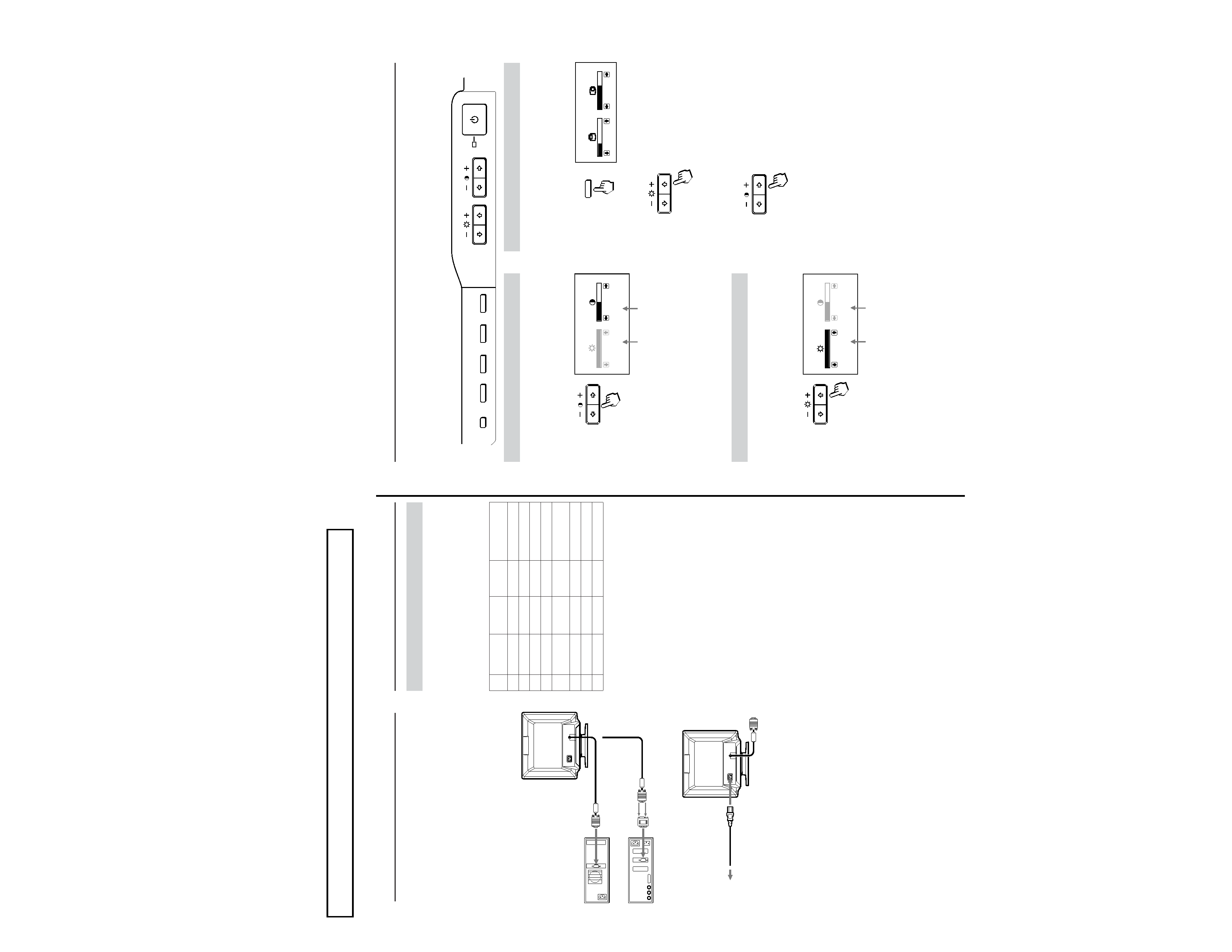
No.
1
2
3
4
5
6
7
8
Horizontal
Frequency
31.5 kHz
43.3 kHz
46.9 kHz
53.7 kHz
49.7 kHz
60.0 kHz
68.7 kHz
64.0 kHz
Resolution
(dots
× lines)
640
× 480
640
× 480
800
× 600
800
× 600
832
× 624
1024
× 768
1024
× 768
1280
× 1024
Graphics
Mode
VGA Graphic 1)
VESA 2)
VESA 2)
VESA2)
Macintosh
16" Color 2)
VESA 2)
VESA 2)
VESA 2)
Vertical
Frequency
60 Hz
85 Hz
75 Hz
85 Hz
75 Hz
75 Hz
85 Hz
60 Hz
Getting Started
Before using this monitor, please make sure that the following
items are included in your package: Multiscan 100
ES/200ES
monitor (1), power cord (1), warranty card (1), "Windows95
Monitor Information Disk" (1), and this operating instruction
manual (1).
This monitor will sync with any IBM or compatible system
equipped with VGA or greater graphics capability. Although
this monitor will sync to other platforms running at horizontal
frequencies between 30 and 70 kHz, including Macintosh and
Power Macintosh system, a cable adapter is required. Please
consult your dealer for advice on which adapter is suitable for
your needs.
Step 1:
With the computer switched off, attach the video
signal cable to the video output.
Step 2:
Attach the power cord to the monitor and the other
end to a power outlet.
Step 3:
Turn on the monitor and computer.
Step 4:
If necessary, adjust the user controls according to
your personal preference.
The installation of your Multiscan 100
ES/200ES is complete.
Enjoy your monitor.
1) VGA is a trademark of IBM Corporation.
2) VESA is a trademark of the non-profit organization, Video
Electronics Standard Association.
3) Macintosh is a trademark of Apple Computer Inc.
4) Windows® is a registered trademark of Microsoft
Corporation in the United States and other countries.
to video output
IBM or compatible
computer
Apple computer
to video output
to a power outlet
Macintosh adapter (not supplied)
Power cord (supplied)
5
COLOR
GEOM
SIZE
CENTER
RESET
Adjusting the Picture Brightness
The adjustment data becomes the common setting for all input
signals.
1 Press the ¨ >/. button.
The "BRIGHTNESS/CONTRAST" OSD appears.
2 Press the ¨ >/. buttons to adjust picture brightness.
. . . . for less brightness
> . . . for more brightness
The "BRIGHTNESS/CONTRAST" OSD disappears 3 seconds
after you release the buttons.
To reset, press the RESET button while the OSD is on.
Adjusting the Picture Centering
The adjustment data becomes the individual setting for each
input signal received.
1 Press the CENTER button.
The "CENTER" OSD appears.
2 For vertical adjustment
Press the ¨ >/. buttons.
> . . . to move up
. . . . to move down
For horizontal adjustment
Press the > ?// buttons.
? . . . to move left
/ . . . to move right
To erase the "CENTER" OSD, press the CENTER button
again.
The "CENTER" OSD automatically disappears 10 seconds after
you release the buttons.
To reset, press the RESET button while the OSD is on.
The horizontal and vertical frequencies for each input signal
received appear on the "BRIGHTNESS/CONTRAST" OSD.
Adjustments
When one of the preset-type signals is input, no picture
adjustment is necessary.
You can, however, adjust the picture to your preferences by
following the procedure described below.
You can adjust all items on the OSD (On Screen Display).
Control Panel
p
Before adjusting the items, turn on the unit and feed the
video signal from the connected computer/work station.
p
Adjustments will be stored automatically.
Horizontal
frequency
Vertical
frequency
BRIGHTNESS/CONTRAST
100
50
31.5 kHz/70Hz
Horizontal
frequency
Vertical
frequency
BRIGHTNESS/CONTRAST
100
50
31.5 kHz/70Hz
Adjusting the Picture Contrast
The adjustment data becomes the common setting for all input
signals.
1 Press the > ?// button.
The "BRIGHTNESS/CONTRAST" OSD appears.
2 Press the > ?// buttons to adjust picture contrast.
/ . . . for more contrast
? . . . for less contrast
The "BRIGHTNESS/CONTRAST" OSD disappears 3 seconds
after you release the buttons.
To reset, press the RESET button while the OSD is on.
CENTER
32
68
CENTER