SERVICE MANUAL
Ver 1.1 2002.04
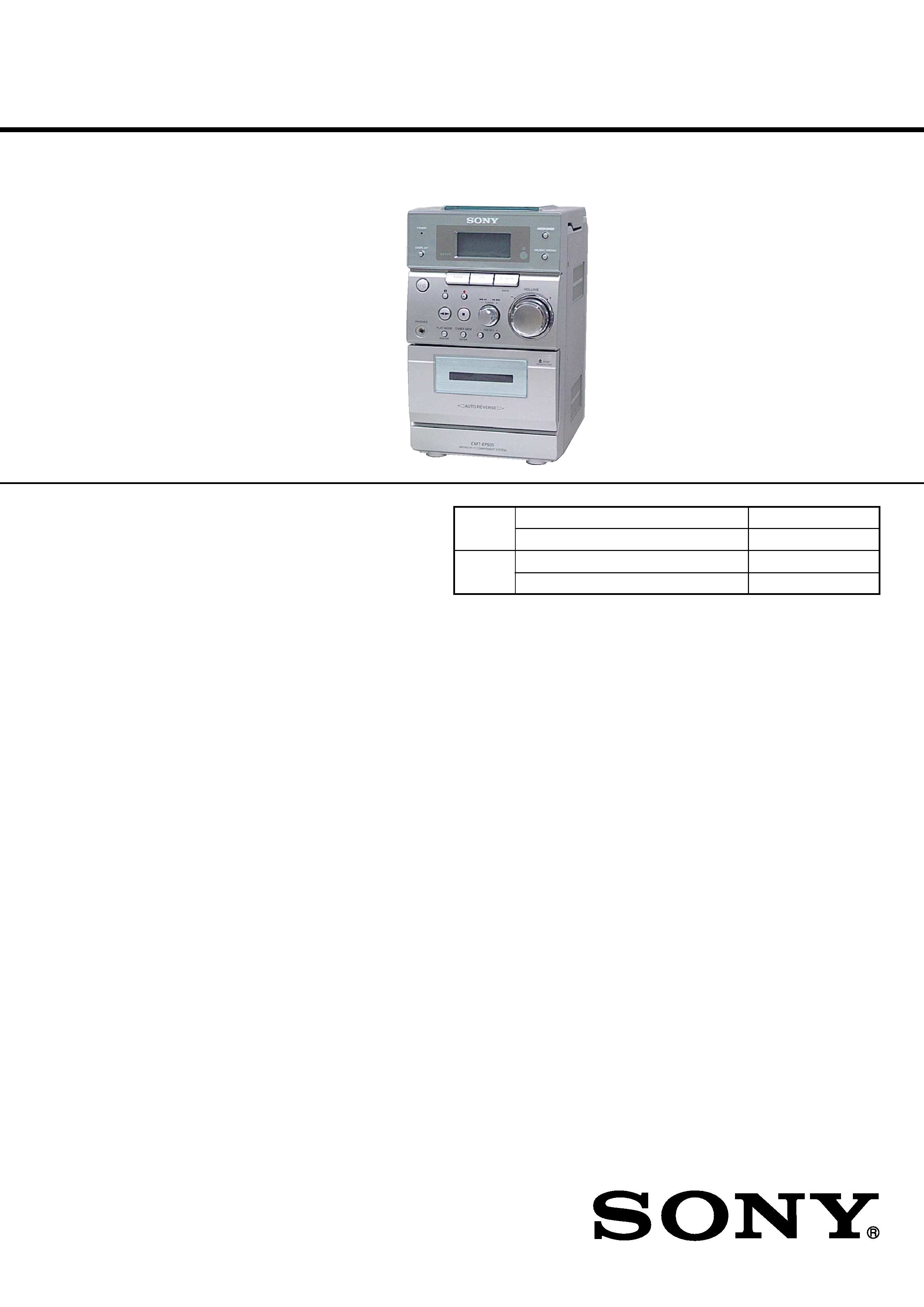
MICRO Hi-Fi COMPONENT SYSTEM
CMT-EP505
CMT-EP505
COMPACT DISC DECK
HCD-EP505
RECEIVER SYSTEM
SPEAKER SYSTEM
SS-CEP505
US Model
Canadian Model
AEP Model
UK Model
E Model
Chinese Model
SPECIFICATIONS
Power requirements
North American model:
120 V AC, 60 Hz
European model:
230 V AC, 50/60 Hz
Mexican model:
120 V AC, 60 Hz
Argentina model:
220 - 230 V AC, 50/60 Hz
Hong Kong model:
230 V AC, 50/60 Hz
Other models:
230 V AC, 50/60 Hz
Power con
U.S.A. model
35 W
Canadian model
35 W
European model
40 W
0.5 W (in the standby mode)
Other models:
40 W
Dimensions (w/h/d):
Approx. 145
× 240 × 252 mm
Mass:
Approx. 3.5 kg
Supplied accessories:
AM loop antenna (1)
Remote Commander (1)
Batteries (2)
FM lead antenna (1)
Design and specifications are subject to change without notice.
· CMT-EP505 is composed of following models.
As for the service manual, it is issued for each component model,
then, please refer to them.
COMPONENT MODEL NAME
1-477-184-11 REMOTE COMMANDER (RM-SEP505)
1-501-843-11 ANTENNA, LOOP (AM)
1-793-184-21 CONNECTOR (F TYPE ADAPTOR)
1-823-170-11 CORD (WITH CONNECTOR) (FM ANT) (AEP, UK, CH)
4-235-505-01 COVER, BATTERY (for RM-SEP505)
4-239-338-11 MANUAL, INSTRUCTION (ENGLISH)
(US, CND, AEP, UK, E51, HK, AR)
4-239-838-21 MANUAL, INSTRUCTION (FRENCH) (CND)
4-239-838-31 MANUAL, INSTRUCTION (SPANISH) (E51, AR)
4-239-338-41 MANUAL, INSTRUCTION (FRENCH, SPANISH) (AEP)
4-239-338-51 MANUAL, INSTRUCTION
(GERMAN, DUTCH, ITALIAN, SWEDISH, POLISH) (AEP)
4-239-338-61 MANUAL, INSTRUCTION (TRADITIONAL CHINESE) (HK)
4-239-339-11 MANUAL, INSTRUCTION (DANISH, FINNISH) (AEP)
4-239-339-21 MANUAL, INSTRUCTION (PORTUGUESE) (AEP)
4-239-339-31 MANUAL, INSTRUCTION (RUSSIAN) (AEP)
4-239-340-11 MANUAL, INSTRUCTION (GREEK) (AEP)
4-239-340-21 MANUAL, INSTRUCTION (HUNGARIAN, CZECH) (AEP)
4-239-340-31 MANUAL, INSTRUCTION (TURKISH) (AEP)
4-239-340-41 MANUAL, INSTRUCTION (SLOVAKIAN) (AEP)
4-241-584-11 MANUAL, INSTRUCTION
(ENGLISH, SIMPLIFIED CHINESE) (CH)
ACCESSORIES
Part No.
Description
Remark
9-873-919-02
Sony Corporation
2002D0500-1
Home Audio Company
C
2002.04
Published by Sony Engineering Corporation
· Abbreviation
AR
: Argentina model
CH
: Chinese model
CND : Canadian model
E51 : Chinese and Peruvian model
HK
: Hong Kong model

2
CMT-EP505
REVISION HISTORY
Clicking the version allows you to jump to the revised page.
Also, clicking the version at the upper right on the revised page allows you to jump to the next revised
page.
Ver.
Date
Description of Revision
1.0
2002.03
New
1.1
2002.04
Addition of US, Canadian, Hong Kong, Chilean and Peruvian,
Argentina model
SERVICE MANUAL
COMPACT DISC DECK RECEIVER
US Model
Canadian Model
AEP Model
UK Model
E Model
Chinese Model
HCD-EP505
Ver 1.1 2002.04
HCD-EP505 is the amplifier, CD
player, tape deck and tuner section
in CMT-EP505.
SPECIFICATIONS
CD
Model Name Using Similar Mechanism
HCD-EP50
Section
CD Mechanism Type
CS-21SC-1280
TAPE
Model Name Using Similar Mechanism
HCD-EP50
Section
Tape Transport Mechanism Type
CRL3439
9-873-673-02
Sony Corporation
2002D0500-1
Home Audio Company
C
2002.04
Published by Sony Engineering Corporation
AUDIO POWER SPECIFICATIONS:
(US model only)
POWER OUTPUT AND TOTAL
HARMONIC DISTORTION:
with 8
loads both channels driven, from 120 -
10,000 Hz; rates 14 W per channel minimum RMS
power, with no more than 10% total harmonic
distortion from 250 mW to rated output.
Amplifier section
Canadian model:
Continuous RMS power output (reference)
14 + 14 W
(8
at 1 kHz, 10% THD)
European model:
DIN power output (rated) 11 + 11 W
(8
at 1 kHz, DIN)
Continuous RMS power output (reference)
14 + 14 W
(8
at 1 kHz, 10% THD)
Music power output (reference)
27 + 27 W
Other models:
The following measured at AC 230 V or AC 120 V,
50/60 Hz
DIN power output (rated) 11 + 11 W
(8
at 1 kHz, DIN)
Continuous RMS power output (reference)
14 + 14 W
(8
at 1 kHz, 10% THD)
Outputs
PHONES:
Accepts headphones of 8
or
(stereo mini jack)
more
SPEAKER:
Accepts impedance of 8 to
16
CD player section
System
Compact disc and digital
audio system
Laser
Semiconductor laser
(
=780 nm)
Emission duration:
continuous
Frequency response
20 Hz - 20 kHz (
±0.5 dB)
Tape player section
Recording system
4-track 2-channel stereo
Frequency response
50 - 13 000 Hz (
±3 dB),
using Sony TYPE I cassette
Wow and flutter
±0.15% W.Peak (IEC)
0.1% W.RMS (NAB)
±0.2% W.Peak (DIN)
Tuner section
FM stereo, FM/AM superheterodyne tuner
FM tuner section
Tuning range
87.5 - 108.0 MHz
Antenna
FM lead antenna
Antenna terminal
75 coaxial
Intermediate frequency 10.7 MHz
AM tuner section
Tuning range
Pan-American model:
530 - 1 710 kHz
(with the interval set at 10 kHz)
531 - 1 710 kHz
(with the interval set at 9 kHz)
European models:
531 -1 602 kHz
(with the interval set at 9 kHz)
Other models:
531 - 1 602 kHz
(with the interval set at 9 kHz)
530 - 1 710 kHz
(with the interval set at 10 kHz)
Antenna
Supplied AM loop antenna
Intermediate frequency 450 kHz
General
Power requirements
North American model: 120 V AC, 60 Hz
European model:
230 V AC, 50/60 Hz
Argentine model:
220 - 230 V AC, 50/60 Hz
Hong Kong model:
230 V AC, 50/60 Hz
Other models:
230 V AC, 50/60 Hz
Power consumption
US model:
35 W
Canadian model:
35 W
European models:
40 W
0.5 W (in the standby mode)
Other models:
40 W
Dimensions (w/h/d)
Approx. 145
× 240× 252 mm
Mass
Approx. 3.5 kg
Supplied accessories:
AM loop antenna (1)
Remote Commander (1)
Batteries (2)
FM lead antenna (1)
Design and specifications are subject to change
without notice.
2
HCD-EP505
Notes on chip component replacement
·Never reuse a disconnected chip component.
· Notice that the minus side of a tantalum capacitor may be dam-
aged by heat.
Flexible Circuit Board Repairing
·Keep the temperature of the soldering iron around 270 °C dur-
ing repairing.
· Do not touch the soldering iron on the same conductor of the
circuit board (within 3 times).
· Be careful not to apply force on the conductor when soldering
or unsoldering.
SAFETY CHECK-OUT
After correcting the original service problem, perform the follow-
ing safety check before releasing the set to the customer:
Check the antenna terminals, metal trim, "metallized" knobs,
screws, and all other exposed metal parts for AC leakage.
Check leakage as described below.
LEAKAGE TEST
The AC leakage from any exposed metal part to earth ground and
from all exposed metal parts to any exposed metal part having a
return to chassis, must not exceed 0.5 mA (500 microamperes.).
Leakage current can be measured by any one of three methods.
1. A commercial leakage tester, such as the Simpson 229 or RCA
WT-540A. Follow the manufacturers' instructions to use these
instruments.
2. A battery-operated AC milliammeter. The Data Precision 245
digital multimeter is suitable for this job.
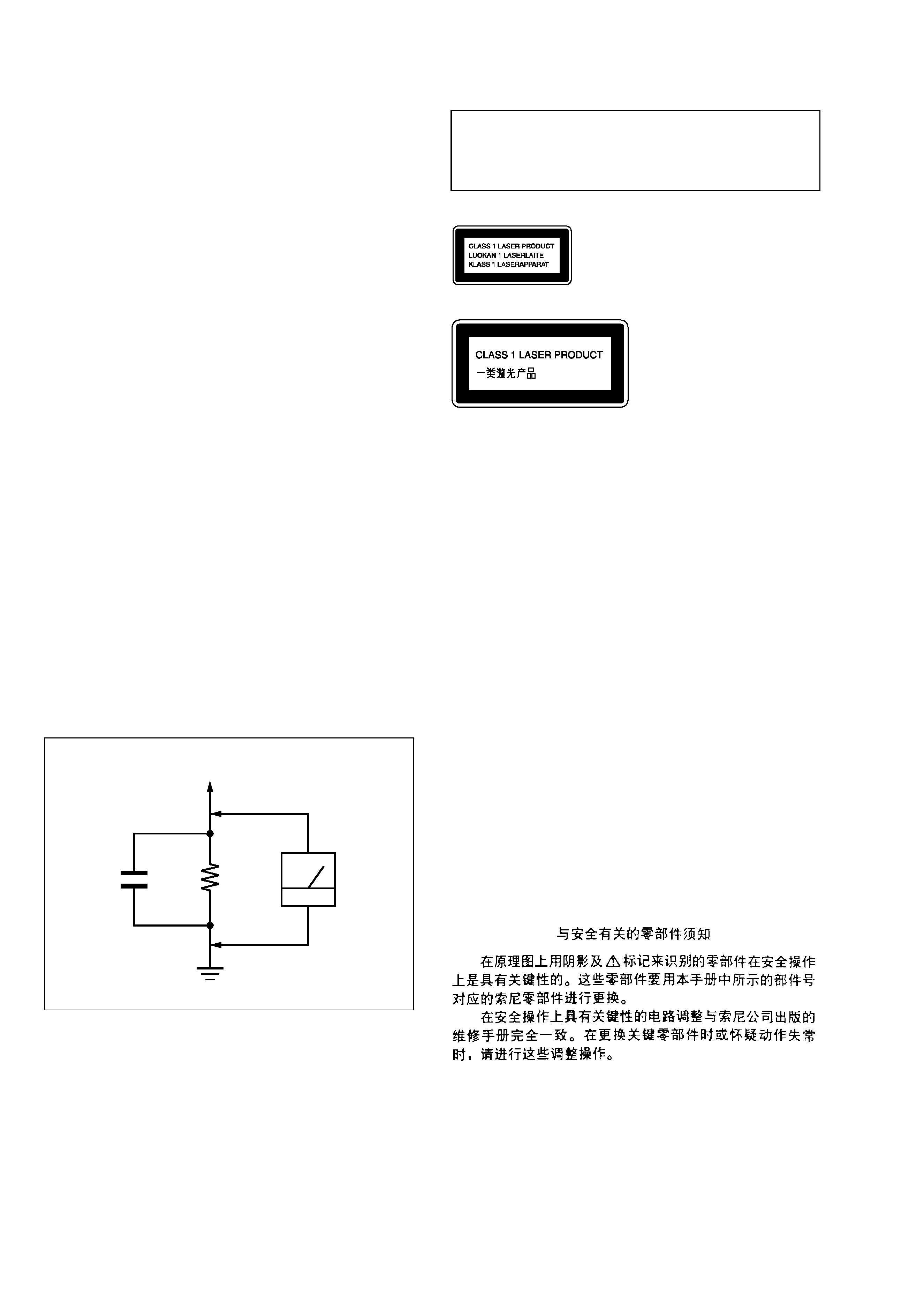
3. Measuring the voltage drop across a resistor by means of a
VOM or battery-operated AC voltmeter. The "limit" indica-
tion is 0.75 V, so analog meters must have an accurate low-
voltage scale. The Simpson 250 and Sanwa SH-63Trd are ex-
amples of a passive VOM that is suitable. Nearly all battery
operated digital multimeters that have a 2 V AC range are suit-
able. (See Fig. A)
CAUTION
Use of controls or adjustments or performance of procedures
other than those specified herein may result in hazardous ra-
diation exposure.
SAFETY-RELATED COMPONENT WARNING!!
COMPONENTS IDENTIFIED BY MARK 0 OR DOTTED
LINE WITH MARK 0 ON THE SCHEMATIC DIAGRAMS
AND IN THE PARTS LIST ARE CRITICAL TO SAFE
OPERATION. REPLACE THESE COMPONENTS WITH
SONY PARTS WHOSE PART NUMBERS APPEAR AS
SHOWN IN THIS MANUAL OR IN SUPPLEMENTS PUB-
LISHED BY SONY.
This appliance is classified as
a CLASS 1 LASER product.
The CLASS 1 LASER
PRODUCT MARKING is
located on the bottom.
Ver 1.1
Fig. A.
Using an AC voltmeter to check AC leakage.
1.5 k
0.15 µF
AC
voltmeter
(0.75 V)
To Exposed Metal
Parts on Set
Earth Ground
ATTENTION AU COMPOSANT AYANT RAPPORT
À LA SÉCURITÉ!
LES COMPOSANTS IDENTIFIÉS PAR UNE MARQUE 0
SUR LES DIAGRAMMES SCHÉMATIQUES ET LA LISTE
DES PIÈCES SONT CRITIQUES POUR LA SÉCURITÉ
DE FONCTIONNEMENT. NE REMPLACER CES COM-
POSANTS QUE PAR DES PIÈCES SONY DONT LES
NUMÉROS SONT DONNÉS DANS CE MANUEL OU
DANS LES SUPPLÉMENTS PUBLIÉS PAR SONY.

3
HCD-EP505
TABLE OF CONTENTS
1.
SERVICING NOTES ................................................ 4
2.
GENERAL ................................................................... 5
3.
DISASSEMBLY
3-1. Disassembly Flow ...........................................................
7
3-2. Front Panel Section .........................................................
8
3-3. MAIN Board ...................................................................
8
3-4. CD Cabinet Section .........................................................
9
3-5. CD Mechanism Deck (CS-21SC-1280) .........................
9
3-6. Tape Mechanism Deck (CRL3439) ................................ 10
3-7. Cassette Lid ..................................................................... 10
4.
MECHANICAL ADJUSTMENTS ....................... 11
5.
ELECTRICAL ADJUSTMENTS ......................... 11
6.
DIAGRAMS
6-1. Block Diagram TUNER Section ............................. 15
6-2. Block Diagram TAPE DECK Section ..................... 16
6-3. Block Diagram MAIN Section ................................ 17
6-4. Block Diagram
DISPLAY/POWER SUPPLY Section ...................... 18
6-5. Note for Printed Wiring Boards and
Schematic Diagrams ....................................................... 19
6-6. Printed Wiring Boards
MAIN Section (AEP, UK, Chinese models) ............ 20
6-7. Schematic Diagram
MAIN Section (AEP, UK, Chinese models) (1/3) ... 21
6-8. Schematic Diagram
MAIN Section (AEP, UK, Chinese models) (2/3) ... 22
6-9. Schematic Diagram
MAIN Section (AEP, UK, Chinese models) (3/3) ... 23
6-10. Printed Wiring Boards MAIN Section
(Except AEP, UK, Chinese models) ............................ 24
6-11. Schematic Diagram MAIN Section
(Except AEP, UK, Chinese models) (1/3) ................... 25
6-12. Schematic Diagram MAIN Section
(Except AEP, UK, Chinese models) (2/3) ................... 26
6-13. Schematic Diagram MAIN Section
(Except AEP, UK, Chinese models) (3/3) ................... 27
6-14. Printed Wiring Board DISPLAY Section ................ 28
6-15. Schematic Diagram DISPLAY Section ................... 29
6-16. Printed Wiring Board POWER Section ................... 30
6-17. Schematic Diagram POWER Section ..................... 31
6-18. IC Pin Function Description ........................................... 34
7.
EXPLODED VIEWS
7-1. Cabinet Section ............................................................... 36
7-2. Front Panel Section-1 ...................................................... 37
7-3. Front Panel Section-2 ...................................................... 38
7-4. CD Cabinet Section ......................................................... 39
8.
ELECTRICAL PARTS LIST ............................... 40
Ver 1.1