Micro Hi-Fi
Component
System
© 2001 Sony Corporation
Operating Instructions
4-233-754-
12 (1)
CMT-CP100
Owner's Record
The model and serial numbers are located at the rear. Record the serial number in the
space provided below. Refer to them whenever you call upon your Sony dealer
regarding this product.
Model No.
Serial No.
2
WARNING
To prevent fire or shock hazard, do not
expose the unit to rain or moisture.
To avoid electrical shock, do not open the cabinet.
Refer servicing to qualified personnel only.
Do not install the appliance in a confined space,
such as a bookcase or built-in cabinet.
This appliance is classified
as a CLASS 1 LASER
product. The CLASS 1
LASER PRODUCT
MARKING is located on
the rear exterior.
To prevent fire, do not cover the ventilation of the
apparatus with news papers, table-cloths, curtains,
etc. And don't place lighted candles on the apparatus.
To prevent fire or shock hazard, do not place vases on
the apparatus.
Don't throw a battery, dispose it as
the injurious wastes.
NOTICE FOR THE CUSTOMERS IN THE
U.S.A.
This symbol is intended to alert the
user to the presence of uninsulated
"dangerous voltage" within the
product's enclosure that may be of
sufficient magnitude to constitute a
risk of electric shock to persons.
This symbol is intended to alert the
user to the presence of important
operating and maintenance (servicing)
instructions in the literature
accompanying the appliance.
CAUTION
The use of optical instruments with this product will
increase eye hazard.
Note to CATV system installer:
This reminder is provided to call the CATV system
installer's attention to Article 820-40 of the NEC that
provides guidelines for proper grounding and, in
particular, specifies that the cable ground shall be
connected to the grounding system of the building, as
close to the point of cable entry as practical.
INFORMATION
This equipment has been tested and found to comply
with the limits for a Class B digital device, pursuant
to Part 15 of the FCC Rules. These limits are
designed to provide reasonable protection against
harmful interference in a residential installation. This
equipment generates, uses, and can radiate radio
frequency energy and, if not installed and used in
accordance with the instructions, may cause harmful
interference to radio communications. However,
there is no guarantee that interference will not occur
in a particular installation. If this equipment does
cause harmful interference to radio or television
reception, which can be determined by turning the
equipment off and on, the user is encouraged to try to
correct the interference by one or more of the
following measures:
Reorient or relocate the receiving antenna.
Increase the separation between the equipment and
receiver.
Connect the equipment into an outlet on a circuit
different from that to which the receiver is
connected.
Consult the dealer or an experienced radio/TV
technician for help.
CAUTION
You are cautioned that any changes or modifications
not expressly approved in this manual could void
your authority to operate this equipment.
NOTICE FOR THE CUSTOMERS IN
CANADA
CAUTION
TO PREVENT ELECTRIC SHOCK, DO NOT USE
THIS POLARIZED AC PLUG WITH AN
EXTENSION CORD, RECEPTACLE OR OTHER
OUTLET UNLESS THE BLADES CAN BE FULLY
INSERTED TO PREVENT BLADE EXPOSURE.
For the customers in North America
ENERGY STAR® is a U.S.
registered mark.
As an
ENERGY STAR® partner,
Sony Corporation has determined
that this product meets the
ENERGY STAR® guidelines for
energy efficiency.

3
Parts Identification
Main unit ............................................... 4
Remote Control ..................................... 5
Getting Started
Hooking up the system .......................... 6
Inserting two size-AA (R6) batteries into
the remote control ........................... 7
Setting the time ...................................... 7
CD
Loading the CD ..................................... 8
Playing the CD
Normal Play/Shuffle Play/Repeat Play .... 8
Programming the CD tracks
Program Play .............................. 9
Using the CD display ............................ 9
Tuner
Presetting radio stations ....................... 10
Listening to the radio
Preset Tuning ........................... 10
Using the Radio Data System (RDS)* .... 11
Tape
Loading a tape ..................................... 12
Playing a tape ...................................... 12
Recording to a tape
CD Synchro Recording/
Recording Manually/Program Edit ... 13
Timer-recording radio programs ......... 14
Sound Adjustment
Adjusting the sound ............................. 16
Other Features
Falling asleep to music
-- Sleep Timer .............................. 16
Waking up to music
-- Daily Timer .............................. 16
Optional Components
Hooking up the optional components.... 18
Additional Information
Precautions .......................................... 19
Troubleshooting ................................... 20
Specifications ...................................... 21
Table of Contents
* European model only
4
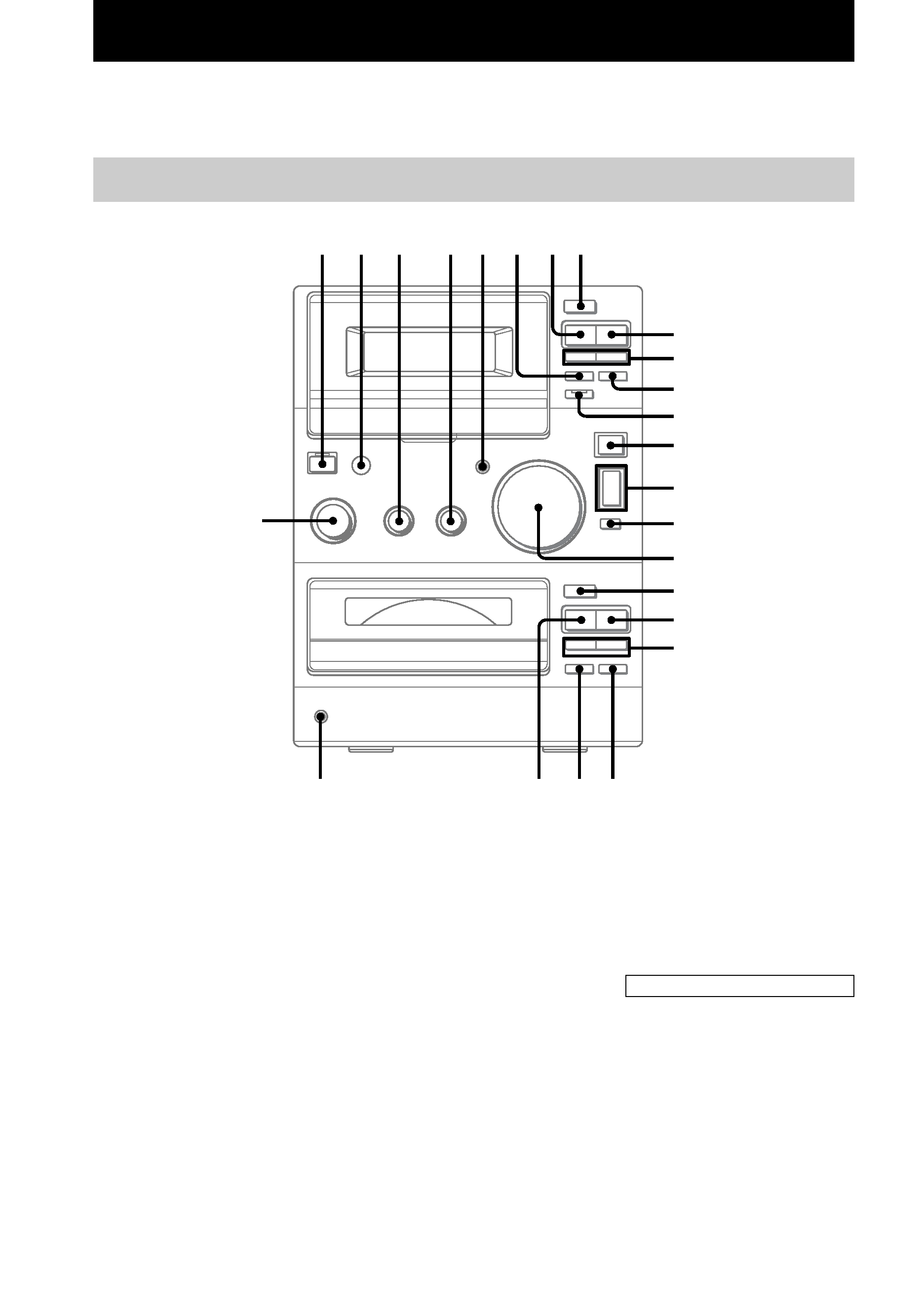
Parts Identification
The items are arranged in alphabetical order.
Refer to the pages indicated in parentheses () for details.
Main unit
BASS 3 (16)
CD EJECT Z qj (8)
CD SYNC qs (13, 14)
CD u ws (8, 9)
CD x qk (8, 9, 21)
CD ./> ql (8, 9)
CD m/M ql (8)
DSG 5 (16, 18)
FUNCTION wf (8~10, 12, 13, 18)
PHONES jack wd
PLAY MODE wa (8, 9, 14)
Remote sensor 2
REPEAT w; (8)
TAPE EJECT Z 8 (12)
TAPE REC z 6 (13)
TAPE Y 7 (12~14)
TAPE X qa (12~14)
TAPE x 9 (12~14, 21)
TAPE m/M 0 (12)
A
Z
Y
?/1
x
m
M
zX
Z
ux
.>
mM
1 2
5
8
9
q;
wf
qd
qf
qg
qj
qk
qa
6
3
4
7
ql
w;
wa
wd
ws
qs
qh
TREBLE 4 (16)
TUNER BAND qd (10, 21)
TUNING MODE qg (10, 11)
TUNING +/ qf (10, 11)
VOLUME qh (17)
BUTTON DESCRIPTIONS
@/1 (power) 1 (7, 10, 14, 17, 18)
Parts
Identification
5
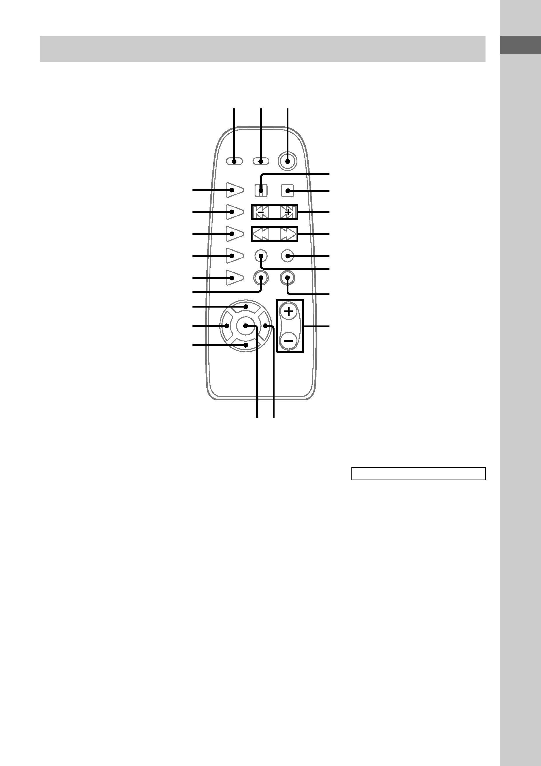
Remote Control
CD REPEAT qk (8)
CD N ws (8, 9)
DIR MODE ql (12~14)
DISPLAY 2 (9, 11)
DSG 1 (16)
ENTER qd (7, 10, 14, 17)
MEMORY qh (10)
PLAY MODE 9 (8, 9, 14)
SLEEP qf (16)
STEREO/MONO qj (11)
TAPE Y w; (12~14)
TIMER SELECT qs (15, 17)
TIMER SET qg (7, 14, 17)
TUNER/BAND wa (10)
TUNING MODE q; (10, 11)
VOL +/ qa (17)
BUTTON DESCRIPTIONS
X 4 (8, 12~14)
x 5 (8, 9, 12~14)
./> 6 (7~10, 14, 17)
m/M 7 (8, 10~12)
@/1 (power) 3 (7, 10, 14, 17)
z REC 8 (13)
12
3
8
5
6
4
9
0
qa
qs
qd
qj
qk
qh
qg
qf
ql
w;
wa
ws
7