
CFS-E2
SERVICE MANUAL
RADIO CASSETTE-CORDER
Model Name Using Similar Mechanism
NEW
Tape Transport Mechanism Type
MF-E2
US Model
Canadian Model
AEP Model
Taiwan Model
Ver 1.3 2002. 08
Sony Corporation
Personal Audio Company
Published by Sony Engineering Corporation
9-923-263-14
2002H1600-1
© 2002.08
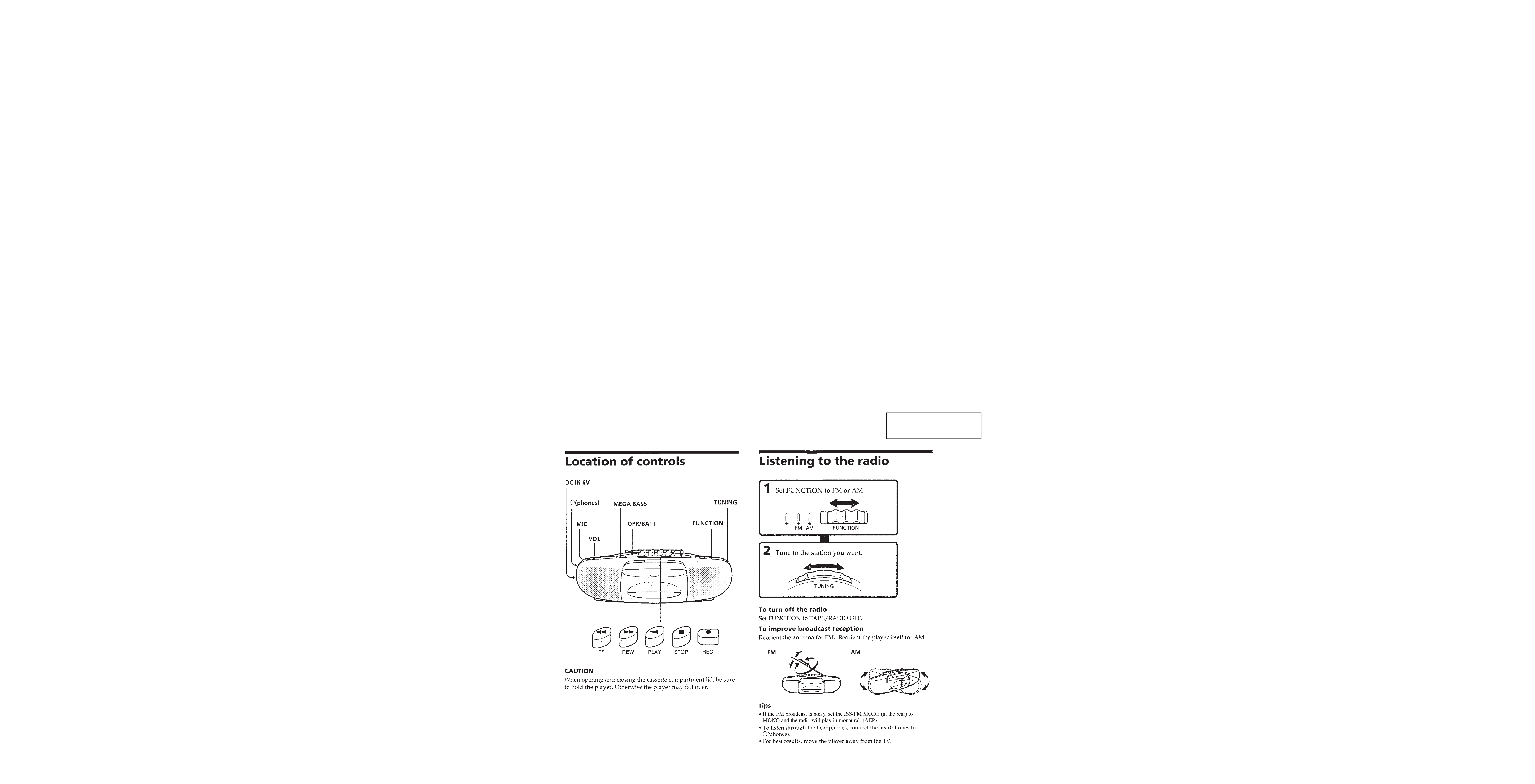
SPECIFICATIONS
· Frequency range
FM : 87.6 108 MHz/AM : 530 1,710 kHz
(US, Canadian, Taiwan)
FM : 87.6 107 MHz/AM : 531 1,602 kHz (AEP)
· Antennas FM : Telescope/AM : Built-in ferrite bar
· Recording system 4-track, 2-channel stereo
· Frequency response 100-10,000 Hz
· Speakers Full-range : 5.7 cm (21/4 inches) dia, cone type
· Output Headphones jack (stereo minijack), for 8-32 ohm
impedance headphones
· Power output 1 W+1 W (at 10% harmonic distortion in
DC operation)
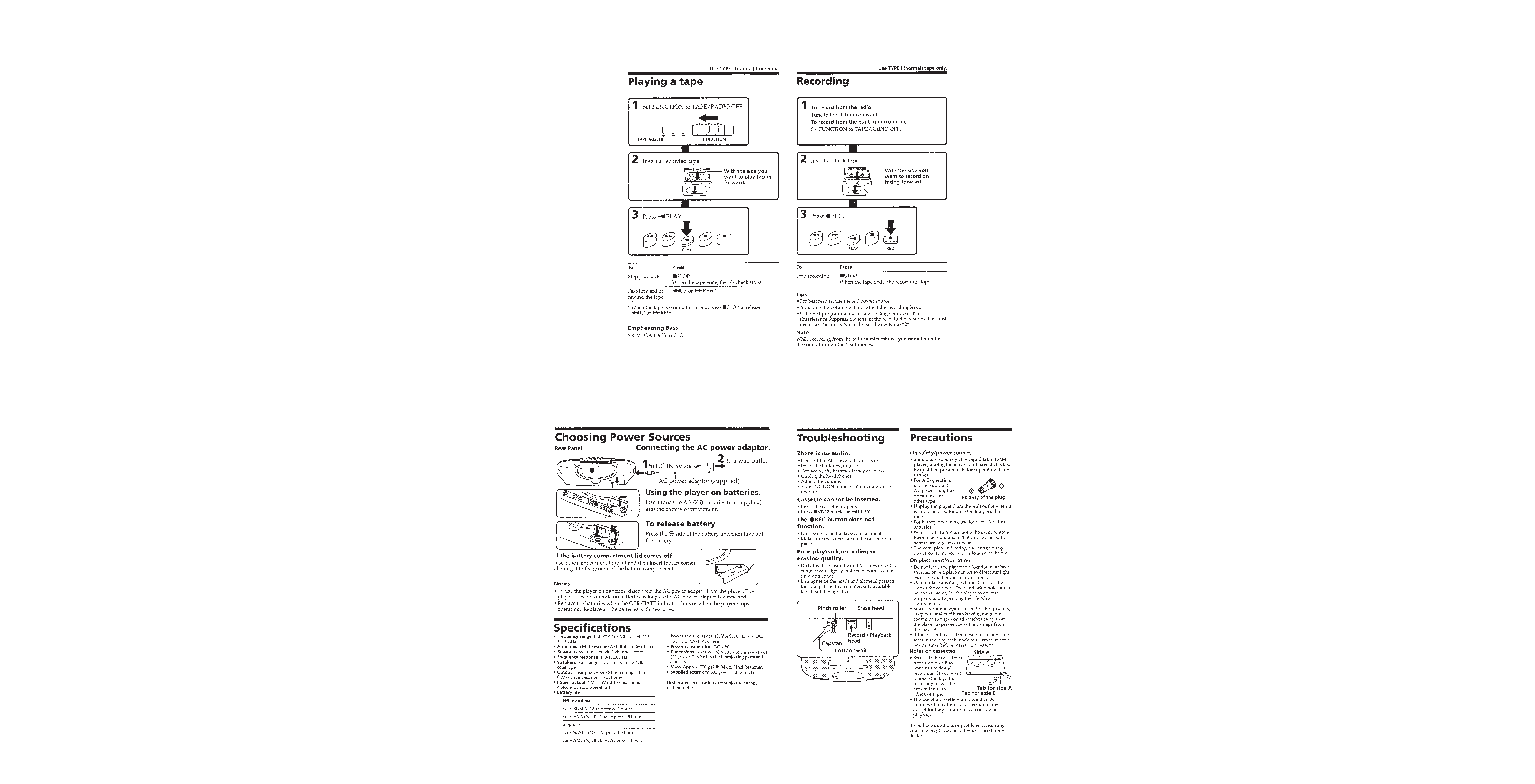
· Battery life
FM recording
Sony SUM-3 (NS) : Approx. 2 hours
Sony AM3 (N) alkaline:Approx. 5 hours
playback
Sony SUM-3 (NS) : Approx.1.5 hours
Sony AM3 (N) alkaline:Approx. 4 hours
· Power requirements 120VAC, 60Hz (US, Canadian, Taiwan)/
220V AC, 50/60Hz (AEP)/ 6V DC, four size
AA (R6) batteries
· Power consumption DC 4 W
· Dimensions Approx. 285 × 101 × 58 mm (w/h/d)
(111/4
× 4 × 23/8 inchs)incl. projecting parts and controls
· Mass Applox. 720 g (1 lb 94 oz)(incl.batteries)
· Supplied accessory AC power adaptor(1)
Design and specifications are subject to change without notice.
-- 2 --
TABLE OF CONTENTS
SAFETY-RELATED COMPONENT WARNING!!
COMPONENTS IDENTIFIED BY MARK
! OR DOTTED LINE WITH
MARK
! ON THE SCHEMATIC DIAGRAMS AND IN THE PARTS
LIST ARE CRITICAL TO SAFE OPERATION. REPLACE THESE
COMPONENTS WITH SONY PARTS WHOSE PART NUMBERS
APPEAR AS SHOWN IN THIS MANUAL OR IN SUPPLEMENTS
PUBLISHED BY SONY.
ATTENTION AU COMPOSANT AYANT RAPPORT
À LA SÉCURITÉ!
LES COMPOSANTS IDENTIFÉS PAR UNE MARQUE
! SUR LES
DIAGRAMMES SCHÉMATIQUES ET LA LISTE DES PIÈCES SONT
CRITIQUES POUR LA SÉCURITÉ DE FONCTIONNEMENT. NE
REMPLACER CES COMPOSANTS QUE PAR DES PIÈSES SONY
DONT LES NUMÉROS SONT DONNÉS DANS CE MANUEL OU
DANS LES SUPPÉMENTS PUBLIÉS PAR SONY.
This section is extracted
from instruction manual.
SECTION 1
GENERAL
1. GENERAL ·············································································· 2
2. DISASSEMBLY
2-1. REAR CABINET SECTION ············································ 4
2-2. MAIN SECTION ······························································ 4
3. MECHANICAL ADJUSTMENTS ········································ 5
4. ELECTRICAL ADJUSTMENTS
4-1. TAPE RECODER SECTION ············································ 5
4-2. TUNER SECTION ···························································· 6
5. DIAGRAMS
5-1. PRINTED WIRING BOARD ··········································· 8
5-2. SCHEMATIC DIAGRAM -- AUDIO SECTION -- ····· 11
5-3. SCHEMATIC DIAGRAM -- TUNER SECTION -- ···· 14
5-4. IC BLOCK DIAGRAMS ················································ 16
6. EXPLODED VIEWS
6-1. FRONT CABINET SECTION ········································ 17
6-2. REAR CABINET SECTION ·········································· 18
6-3. MECHANISM DECK-1 ················································· 19
6-4. MECHANISM DECK-2 ················································· 20
7. ELECTRICAL PARTS LIST ··············································· 21
-- 3 --
-- 4 --
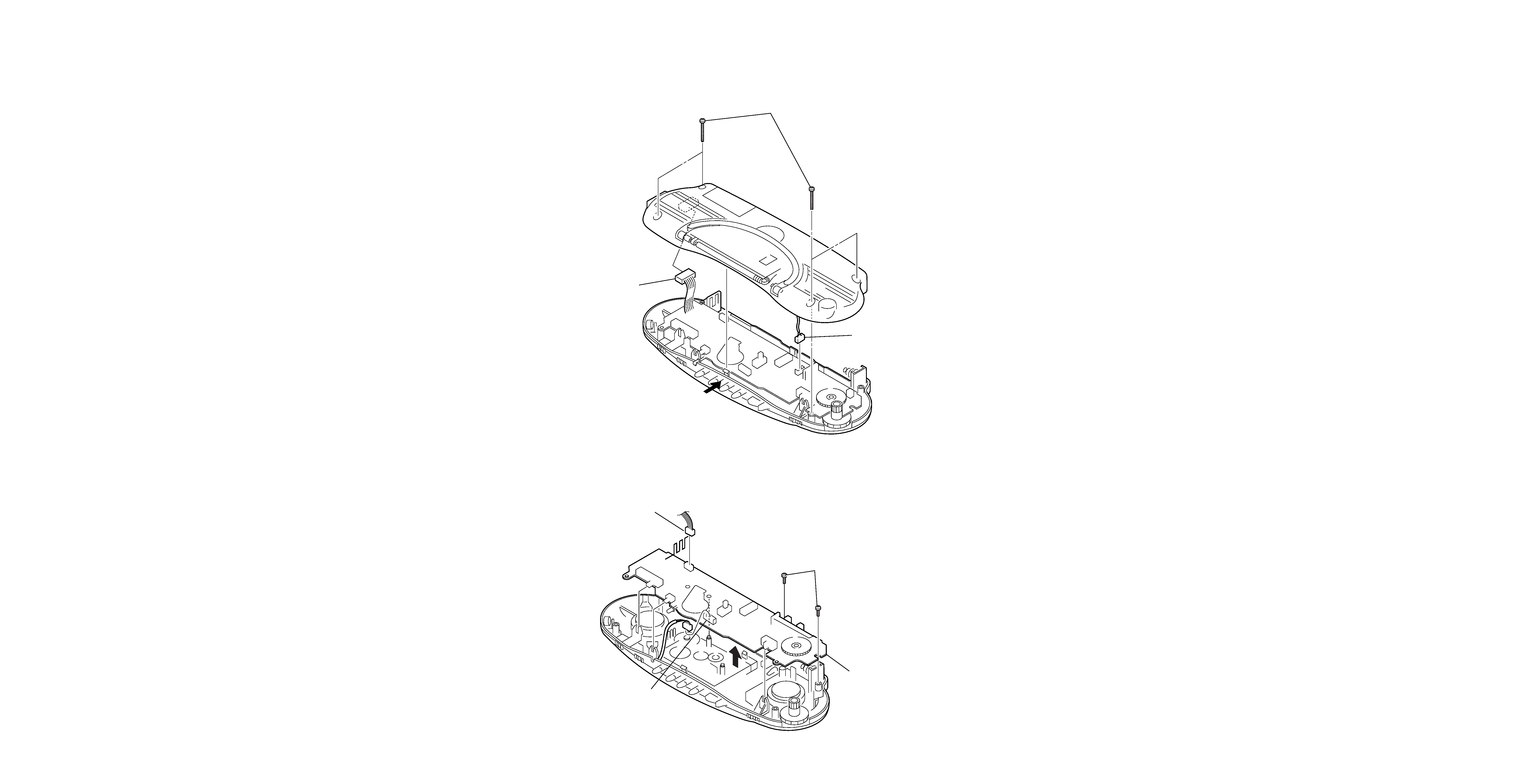
SECTION 2
DISASSEMBLY
Note : Follow the disassembly procedure in the numerical order given.
2-1. REAR CABINET
2-2. MAIN BOARD
1 Four screws (+ BVTP 3
× 24)
3 Connector (CN305)
4 Connector (CN1)
2 Unlock the claw
by pressing here.
3 Connector (CN301)
4 Main board
1 Two screws (+P 2.6
× 8)
2 Connector (CN304)

CFS-E2
Tape Speed Adjustment
Procedure:
Mode : FWD playback
Adjustment Value : normal tape speed
Confirm that the frequency difference between the tape top and
tape end is within 1.5 % (45 Hz).
Adjustment element : RV601
PRECAUTION
·
Clean the following parts with a denatured-alchool-moistened
swab:
record/playback head
erase head
pinch rollers
playback head
rubber belts
idlers
capstan
·
Demagnetize the record/playback head with a head
demagnetizer.
(Do not bring a head demagnetiger close to the erase head.)
·
Do not use a magnetized screwdriver for the adjustments.
·
After the adjustments, apply suitable locking compound to the
parts adjusted.
·
Perform adjustment under the specified voltage (DC6V) unless
otherwise specified.
Torque Measurement
Tape Tension
SECTION 3
MECHANICAL ADJUSTMENTS
Tension Meter
CQ-403A
Mode
FWD
Meter reading
70g or more
Meter reading
22.5 to 55g · cm
2.5 to 5g · cm
45 to120g · cm
Mode
FWD
FWD
back tension
FF, REW
Torque Meter
CQ-102C
CQ-102C
CQ-201B
4-1.
TAPE RECODER SECTION
0 dB = 0.775 V
PRECAUTION
1.
Adjustments should be performed in the order given. (Generally
playback circuit adjustments should be completed before
preforming recording circuit adjustments.)
2.
Adjustments should be performed for both L-ch and R-ch.
(Switches and controls should be set as follows unless otherwise
specified.)
·
Switch position
FUNCTION
: TAPE (RADIO OFF)
TONE
: Maximum
MEGA BASS : ON
VOLUME
: Maximum
·
Test tape
SECTION 4
ELECTRICAL ADJUSTMENTS
Test Tape
WS-48A
Used for
Tape speed adjustment
Signal
3 kHz, 0 dB
Frequency counter
2,980 to 3,020 Hz
DECK
B
4-2.
TUNER SECTION
0 dB = 1 µV
·
AM section
FUNCTION
: RADIO
BAND
: AM
·
FM section
FUNCTION
: RADIO
BAND
: AM
Repeat the above adjustments unit the level meter reading is
maximized.
AM Tracking Adjustment
Make adjustment unit the level meter defection is maximized.
ANT2
620kHz
CT1
1,400 kHz
AM Frequency Coverage Adjustment
Make adjustment unit the level meter defection is maximized.
T1
520kHz (520kHz)
CT4
1,710kHz (1,680kHz)
FM Frequency Coverage Adjustment
Make adjustment unit the level meter defection is maximized.
L2
86.5MHz (87.0MHz)
CT3
109.5MHz (107.8MHz)
FM Tracking Adjustment
Make adjustment unit the level meter defection is maximized.
L1
86.5MHz (87.0MHz)
CT2
109.5MHz (107.8MHz)
FM Separation Adjustment
Adjustment method:
FUNCTION switch
FM
Adjust T2 unit the L-channel output minized.
-- 5 --
-- 6 --
-- 7 --
CT2
L1
CT3
S101
CT4
RV1
T2
T1
RV601
RV301
CT1
L2
Adjustment location : MAIN board (Component side)
FM VCO Adjustment
Procedure:
1.
Connect frequency counter to the positions shown below.
2.
Tune the set to 98MHz.
3.
Adjust RV1 for 75.5 to 76.5kHz reading on the frequency
counter.
(
) : AEP model
(
) : AEP model
(
) : AEP model
Ver 1.2 2001. 04