Ver 1.0 1998. 07
MICROFILM
CFD-V14
SERVICE MANUAL
CD RADIO CASSETTE-CORDER
SPECIFICATIONS
AEP Model
UK Model
Model Name Using
CD Section
CFD-V24
Similar Mechanism
Tape Section
CFD-V24
Optical Pick-up Type
KSM-213CDM
Tape Transport Mechanism Type
MF-V10-117
CD player Section
System
Compact disc digital audio system
Laser diode properties
Material: GaAlAs
Wave length: 780 nm
Emission duration : Continuous
Laser output : Less than 44.6
µW
(This output is the value measured at a distance of about 200
mm from the objective lens surface on the optical pick-up
block with 7 mm aperture.)
Spindle speed
200 r/min (rpm) to 500 r/min (rpm) (CLV)
Number of channels
2
Frequency response
20 20,000 Hz +1 /2 dB
Wow and flutter
Below measurable limit
Radio section
Frequency range
FM : 87.6 107 MHz (AEP, UK, Russian model)
87.5 108 MHz (Italian model)
65 108 MHz (East European model)
AM : 531 1,602 kHz (AEP, UK, East European,
Russian model)
526.5 1,606.5 kHz (Italian model)
IF
FM : 10.7 MHz
AM : 455 kHz
Aerials
FM : Telescopic aerial
AM : Built-in ferrite bar aerial
Cassette-corder section
Recording system
4-track 2 channel stereo
Fast winding time
Approx. 120 s (sec.) with Sony cassette C-60
Frequency response
TYPE I (normal): 70 l0,000 Hz
General
Speaker
Full range: 10 cm dia., 3.2 ohms, cone type (2)
Outputs
Headphones jack (stereo minijack)
For 16 68 ohms impedance headphones
Maximum Power output
2.3 W + 2.3 W
Continued on page 2
2
SAFETY-RELATED COMPONENT WARNING!!
COMPONENTS IDENTIFIED BY MARK
! OR DOTTED LINE WITH
MARK
! ON THE SCHEMATIC DIAGRAMS AND IN THE PARTS
LIST ARE CRITICAL TO SAFE OPERATION.
REPLACE THESE COMPONENTS WITH SONY PARTS WHOSE
PART NUMBERS APPEAR AS SHOWN IN THIS MANUAL OR IN
SUPPLEMENTS PUBLISHED BY SONY.
TABLE OF CONTENTS
Power requirements
For CD radio cassette-corder
230V AC, 50Hz
9V DC, 6 size D (R20) batteries
Power consumption
AC 20 W
Battery life
For CD radio cassette-corder :
FM recording
Sony R20P : approx. 13.5 h
Sony alkaline LR20 : approx. 20 h
Tape playback
Sony R20P : approx. 7.5 h
Sony alkaline LR20 : approx. 15 h
CD playback
Sony R20P : approx. 2.5 h
Sony alkaline LR20 : approx. 7 h
Dimensions
Approx. 425 x 160 x 246 mm (w/h/d)
(16 3/4 x 6 3/8 x 9 3/4 inches) (incl. projecting parts)
Mass
Approx. 4.0 kg (8 lb. 13 oz) (incl. batteries)
Supplied accessories
AC power cord (1 )
Design and specifications are subject to change without notice.
Specifications ........................................................................... 1
1. SERVICING NOTES .................................................... 3
2. GENERAL
Location and Function of Controls .................................... 3
3. DISASSEMBLY
3-1. Front Cabinet Section, Rear Cabinet Section,
Contorl Board ............................................................. 4
3-2. Power Board, AC Inlet Board,
BATT Board ............................................................... 4
3-3. Upper Cabinet ............................................................. 5
3-4. Mechanism Deck, REC SW Board,
MONO/ST SW Board ................................................. 5
3-5. Optical pick-up Section, CD Motor Board ................. 6
3-6. Main Board ................................................................. 6
4. DIAL POINTER INSTALLATION ............................ 7
5. ADJUSTMENTS
5-1. Mechanical Adjustments ............................................ 8
5-2. Electrical Adjustments ................................................ 8
6. DIAGRAMS
6-1. Explanation of IC Terminals ...................................... 11
6-2. Block Diagrams ........................................................ 13
6-3. Printed Wiring Boards .............................................. 17
6-4. Schematic Diagram (Main Section) ......................... 21
6-5. Schematic Diagram (CD Section) ............................ 25
7. EXPLODED VIEWS
7-1. Front Cabinet Section ............................................... 32
7-2. Upper Cabinet Section .............................................. 33
7-3. Rear Cabinet Section ................................................ 34
7-4. Mechanism Deck Section (1) ................................... 35
7-5. Mechanism Deck Section (2) ................................... 36
7-6. Optical pick-up Section ............................................ 37
8. ELECTRICAL PARTS LIST ................................ 38
This Compact Disc player is
classified as a CLASS 1 LASER
product.
The CLASS 1 LASER
PRODUCT label is located on
the rear exterior.
CAUTION
Use of controls or adjustments or performance
of procedures other than those specified herein
may result in hazardous radiation exposure.
Laser component in this product is capable of emitting
radiation exceeding the limit for Class 1.
3
NOTES ON HANDLING THE OPTICAL PICK-UP
BLOCK OR BASE UNIT
The laser diode in the optical pick-up block may suffer electro-
static breakdown because of the potential difference generated
by the charged electrostatic load, etc. on clothing and the human
body.
During repair, pay attention to electrostatic breakdown and also
use the procedure in the printed matter which is included in the
repair parts.
The flexible board is easily damaged and should be handled
with care.
NOTES ON LASER DIODE EMISSION CHECK
The laser beam on this model is concentrated so as to be focused
on the disc reflective surface by the objective lens in the optical
pick-up block. Therefore, when checking the laser diode
emission, observe more than 30 cm away from the objective
lens.
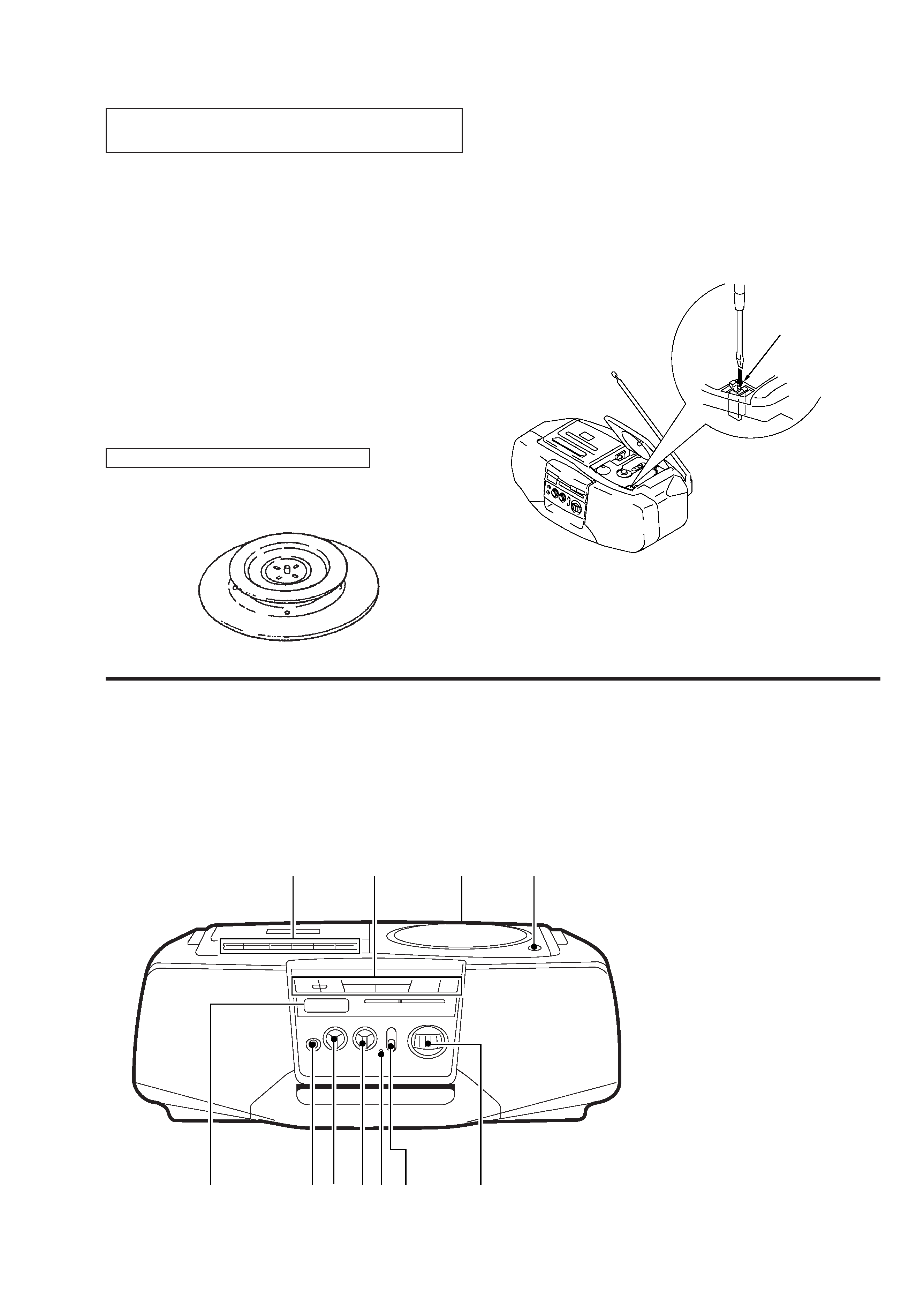
CHUCK PLATE JIG ON REPAIRING
On repairing CD section, playing a disc without the CD lid, use
Chuck Plate Jig.
· Code number of Chuck Plate Jig : X-4918-255-1
SECTION 1
SERVICING NOTES
LASER DIODE AND FOCUS SEARCH OPERATION
CHECK
1. Press CD open knob.
2. Open the lid for CD.
3. Push on SWITCH (S801) as following figure.
4. Confirm the laser diode emission while observing the
objecting lens. When there is no emission, Auto Power
Control circuit or Optical Pick-up is broken.
Objective lens moves up and down once for the focus
search.
Insert a precision
screw driver and push
SWITCH (S801)
SECTION 2
GENERAL
1 Tape operation buttons
r REC button
" PLAY button
0 REW button
) FF button
p6 STOP/EJECT button
P PAUSE button
2 CD operation buttons
button
± button
PLAY MODE button
DISPLAY/ENTER button
fl button
p button
3 FM MODE switch
4 OPEN / CLOSE button
5 Information display
6 2 (Phones) jack
7 VOLUME knob
8 TONE knob
9 OPR / BATT indicator
!º FUNCTION switch
!¡ TUNING knob
LOCATION AND FUNCTION OF CONTROLS
MAIN UNIT
12
5
6 79
80
!¡
34
4
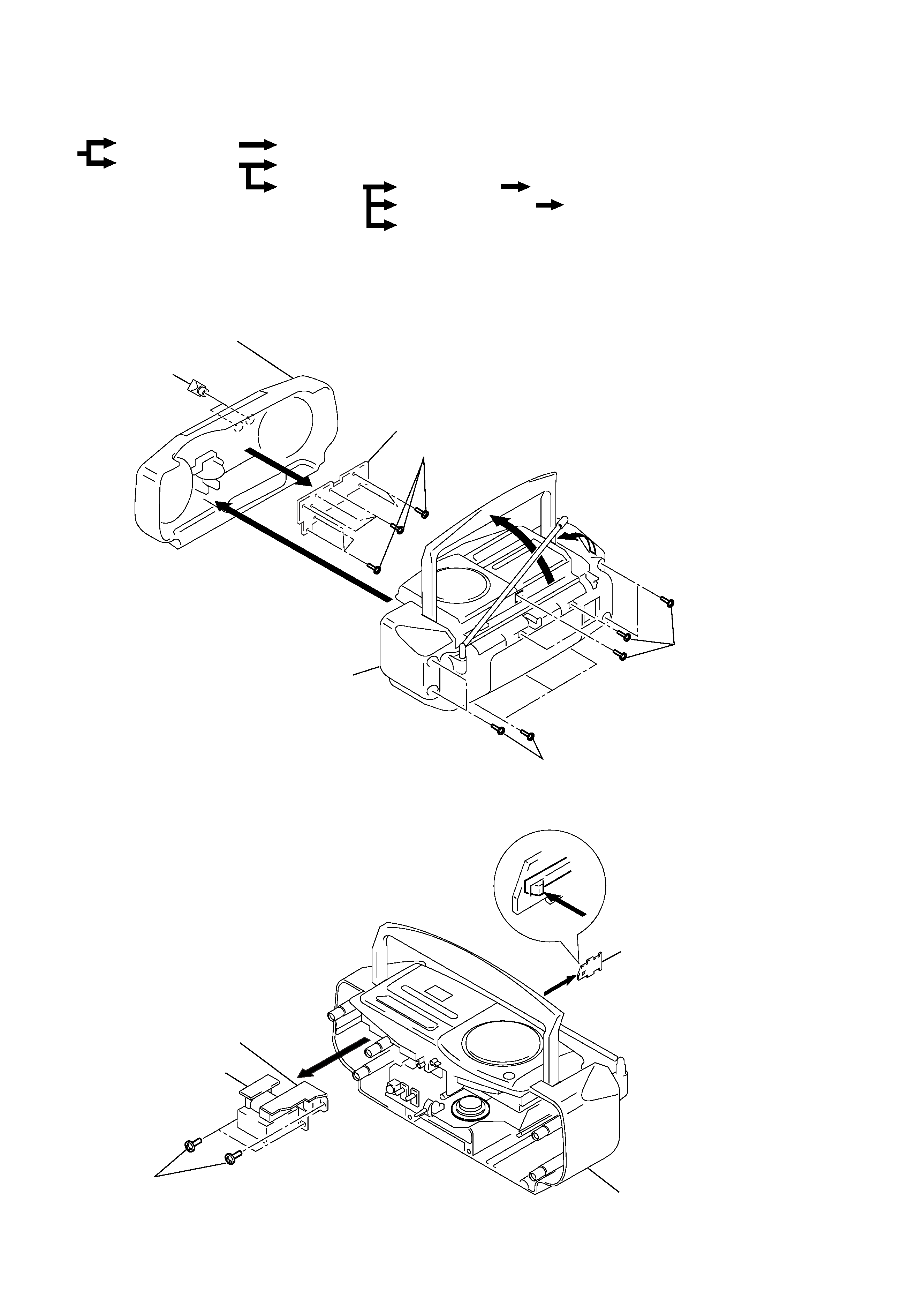
SECTION 3
DISASSEMBLY
Note : Follow the disassembly procedure in the numerical order given.
3-1. FRONT CABINET SECTION, REAR CABINET SECTION, CONTROL BOARD
3-2. POWER BOARD, AC INLET BOARD, BATT BOARD
r
The equipment can be removed using the following procedure.
Upper cabinet
Optical pick-up section
Front cabinet section
Mechanism deck
Set
Rear cabinet section
Control board
MONO/ST SW board
REC SW board
Power board, AC inlet board, BATT board
Main board, CD motor board
4 Knob, VOL
6 Screws +BVTP (2.6X8)
Control board
Front cabinet section
5
1
2
3 Screws +BVTP (3X14)
3 Screws +BVTP (3X14)
Rear cabinet section
7
1 Screws +BVTP (3X10)
3
4
Power board
AC inlet board
Rear cabinet section
BATT board
2
5
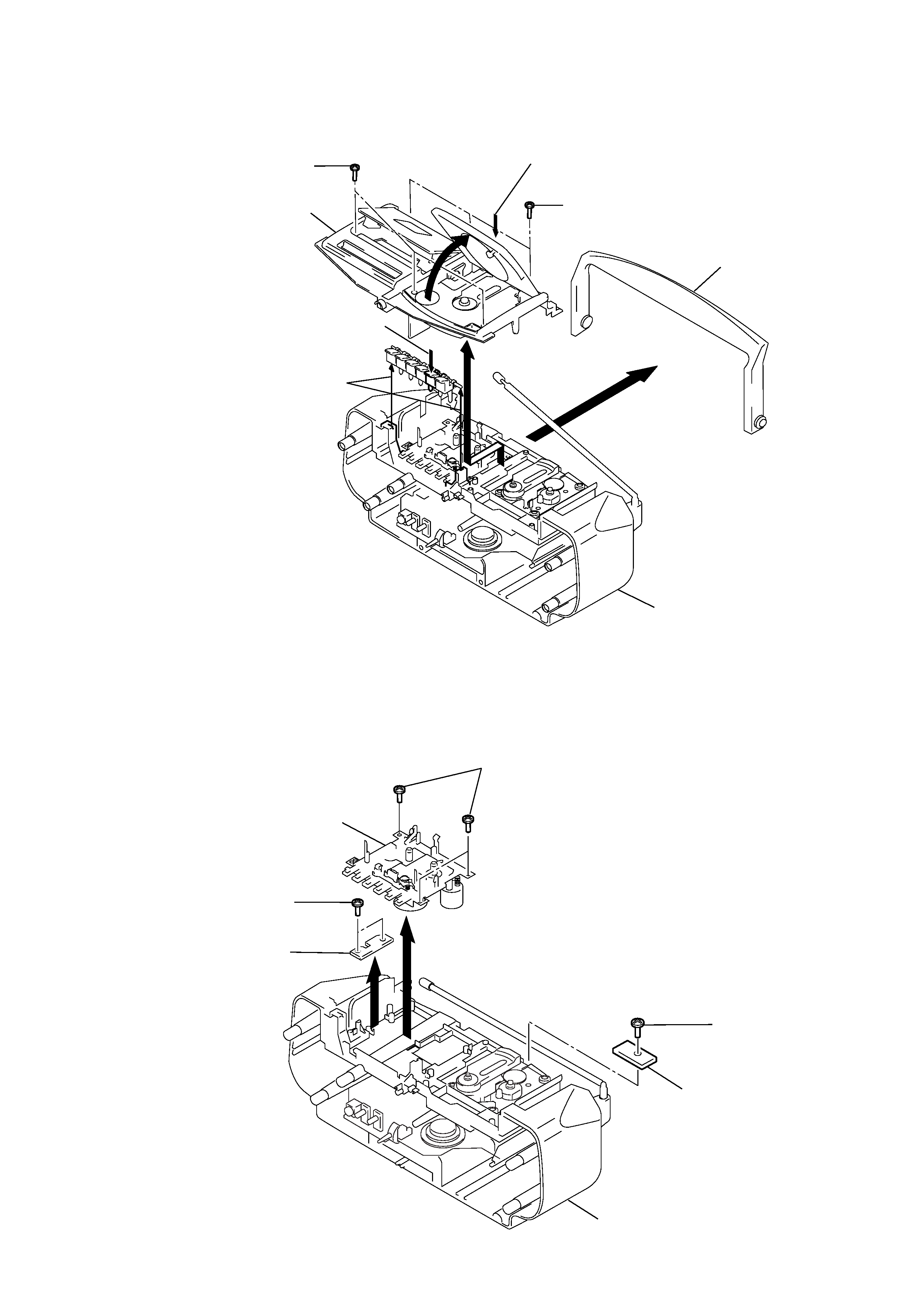
3-3. UPPER CABINET
3-4. MECHANISM DECK, REC SW BOARD, MONO/ST SW BOARD
4 Screws +BVTP (3X10)
1 STOP/EJECT
Handle
Rear cabinet section
Upper cabinet
7
5
2
6
2 PUSH OPEN/CLOSE
3 Screws
+BVTP (3X10)
REC SW board
3 Screws +BVTP (3X10)
4
2
Mechanism deck
1 Screws +BVTP (3X10)
MONO/ST SW board
5 Screw +BVTP (3X8)
Rear cabinet section