SERVICE MANUAL
CD RADIO CASSETTE-CORDER
US Model
Canadian Model
E Model
Australian Model
SPECIFICATIONS
CFD-E55
Model Name Using Similar Mechanism
CFD-Z500
CD
CD Mechanism Type
KSM-213CDM
Section
Optical Pick-up Name
KSS-213C
TAPE
Model Name Using Similar Mechanism
CFD-Z500
Section
Tape Transport Mechanism Type
MF-Z500-117
IF
FM: 10.7 MHz
AM/MW: 450 kHz
Aerials
FM: Telescopic aerial
AM/MW: Built-in ferrite bar aerial
Cassette-corder section
Recording system
4-track 2 channel stereo
Fast winding time
Approx. 120 sec. with Sony cassette C-60
Frequency response
TYPE I (normal): 70 - 13,000 Hz
General
Speaker
Full range: 8 cm (3 1/4 in.) dia.,
3.2 ohms, cone type (2)
Outputs
Headphones jack (stereo minijack)
For 16 - 68 ohms impedance headphones
Power output (excluding for US model)
2 W + 2 W (at 3.2 ohms, 10 % harmonic distortion
in AC operation)
Power requirements
For CD radio cassette-corder:
120 V AC, 60 Hz (US, Canadian, E92*,
Mexican models)
230 V AC, 50Hz (Singapore, Argentine,
Australian models)
9 V DC, 6 size D (R20) batteries
For memory back-up:
4.5 V DC, 3 size AA (R6) batteries
AUDIO POWER SPECIFICATIONS
(US model only)
POWER OUTPUT AND TOTAL
HARMONIC DISTORTION
With 3.2-ohm loads, both channels driven
from 100 - 10,000 Hz; rated 1.5 W per
channel-minimum RMS power, with no more
than 10 % total harmonic distortion in AC
operation.
Other Specifications
CD player section
System
Compact disc digital audio system
Laser diode properties
Material: GaAlAs
Wave length: 780 nm
Emission duration: Continuous
Laser output: Less than 44.6 µW
(This output is the value measured at a distance of
about 200 mm from the objective lens surface on
the optical pick-up block with 7 mm aperture.)
Spindle speed
200 r/min (rpm) to 500 r/min (rpm) (CLV)
Number of channels
2
Frequency response
20 - 20,000 Hz +0/0.5 dB
Wow and flutter
Below measurable limit
Radio section
US, Canadian, E92*, Mexican models
Frequency range
FM: 87.6 - 108 MHz
AM: 530 - 1,710 kHz
Aerials
FM: Telescopic aerial
AM: Built-in ferrite bar aerial
Singapore, Argentine, Australian models
Frequency range
FM: 87.6 - 108 MHz
AM: 531 - 1,602 kHz
Power consumption
AC 17 W
Battery life
For CD radio cassette-corder:
FM recording
Sony manganese SUM-1 (N): approx. 9 h
Sony alkaline AM-1 (N): approx. 19 h
Tape playback
Sony manganese SUM-1 (N): approx. 5 h
Sony alkaline AM-1 (N): approx. 14 h
CD playback
Sony manganese SUM-1 (N): approx. 1.5 h
Sony alkaline AM-1 (N) : approx. 7 h
Dimensions
Approx. 304
× 169 × 262 mm (w/h/d)
(12
× 6 3/4 × 10 3/8 inches) (incl. projecting parts)
Mass
Approx. 3.6 kg (7 lb. 15 oz) (incl. batteries)
Supplied accessories
AC power cord (1)
Instruction manual (1)
*E92: Central and South America
Design and specifications are subject to change without
notice.
Ver. 1.2 2005.09
9-927-159-13
2005I05-1
© 2005.09
Sony Corporation
Personal Audio Group
Published by Sony Engineering Corporation
2
ATTENTION AU COMPOSANT AYANT RAPPORT
À LA SÉCURITÉ!
LES COMPOSANTS IDENTIFIÉS PAR UNE MARQUE 0
SUR LES DIAGRAMMES SCHÉMATIQUES ET LA LISTE
DES PIÈCES SONT CRITIQUES POUR LA SÉCURITÉ
DE FONCTIONNEMENT. NE REMPLACER CES COM-
POSANTS QUE PAR DES PIÈCES SONY DONT LES
NUMÉROS SONT DONNÉS DANS CE MANUEL OU
DANS LES SUPPLÉMENTS PUBLIÉS PAR SONY.
SAFETY-RELATED COMPONENT WARNING!!
COMPONENTS IDENTIFIED BY MARK 0 OR DOTTED
LINE WITH MARK 0 ON THE SCHEMATIC DIAGRAMS
AND IN THE PARTS LIST ARE CRITICAL TO SAFE
OPERATION. REPLACE THESE COMPONENTS WITH
SONY PARTS WHOSE PART NUMBERS APPEAR AS
SHOWN IN THIS MANUAL OR IN SUPPLEMENTS PUB-
LISHED BY SONY.
1.
SERVICING NOTES ..............................................
3
2.
GENERAL ..................................................................
5
3.
DISASSEMBLY ........................................................
8
4.
MECHANICAL ADJUSTMENTS ...................... 14
5.
ELECTRICAL ADJUSTMENTS
Tape Deck Section ......................................................... 14
Tuner Section ................................................................. 15
CD Section ..................................................................... 17
6.
DIAGRAMS
6-1. Block Diagram CD Section .................................... 19
6-2
Block Diagram TUNER Section ............................ 21
6-3. Block Diagram MAIN Section (Type A) ............... 23
6-4. Block Diagram MAIN Section (Type B, C) ........... 25
6-5. Block Diagram MAIN Section (Type D) ............... 27
6-6. Block Diagram POWER SUPPLY Section ............ 29
6-7. Printed Wiring Boards
CD Section (Type A, B, C) ...................................... 33
6-8. Printed Wiring Boards CD Section (Type D) ......... 35
6-9. Schematic Diagram
CD Section (Type A, B, C, D) ................................. 37
6-10. Printed Wiring Boards
MAIN/POWER SUPPLY Section (Type A, B) ....... 42
6-11. Printed Wiring Boards
MAIN/POWER SUPPLY Section (Type C) ............ 45
6-12. Printed Wiring Boards
MAIN/POWER SUPPLY Section (Type D) ........... 50
6-13. Schematic Diagram
MAIN (TUNER) Section (Type A, B, C, D) ........... 53
6-14. Schematic Diagram
MAIN (AUDIO) Section (Type A, B, C, D),
POWER SUPPLY Section (Type A, B, C) ................. 58
6-15. Schematic Diagram
POWER SUPPLY Section (Type D) ....................... 61
6-16. Printed Wiring Boards
DISPLAY Section (Type A, B) ................................ 63
6-17. Printed Wiring Boards
DISPLAY Section (Type C) ..................................... 65
6-18. Printed Wiring Boards
DISPLAY Section (Type D) .................................... 67
6-19. Schematic Diagram
DISPLAY Section (Type A, B, C, D) ...................... 69
6-20. IC Pin Function Description .......................................... 76
7.
EXPLODED VIEWS ............................................... 78
8.
ELECTRICAL PARTS LIST .............................. 85
TABLE OF CONTENTS
SAFETY CHECK-OUT
After correcting the original service problem, perform the follow-
ing safety check before releasing the set to the customer:
Check the antenna terminals, metal trim, "metallized" knobs,
screws, and all other exposed metal parts for AC leakage.
Check leakage as described below.
LEAKAGE TEST
The AC leakage from any exposed metal part to earth ground and
from all exposed metal parts to any exposed metal part having a
return to chassis, must not exceed 0.5 mA (500 microamperes).
Leakage current can be measured by any one of three methods.
1. A commercial leakage tester, such as the Simpson 229 or RCA
WT-540A. Follow the manufacturers' instructions to use these
instruments.
2. A battery-operated AC milliammeter. The Data Precision 245
digital multimeter is suitable for this job.
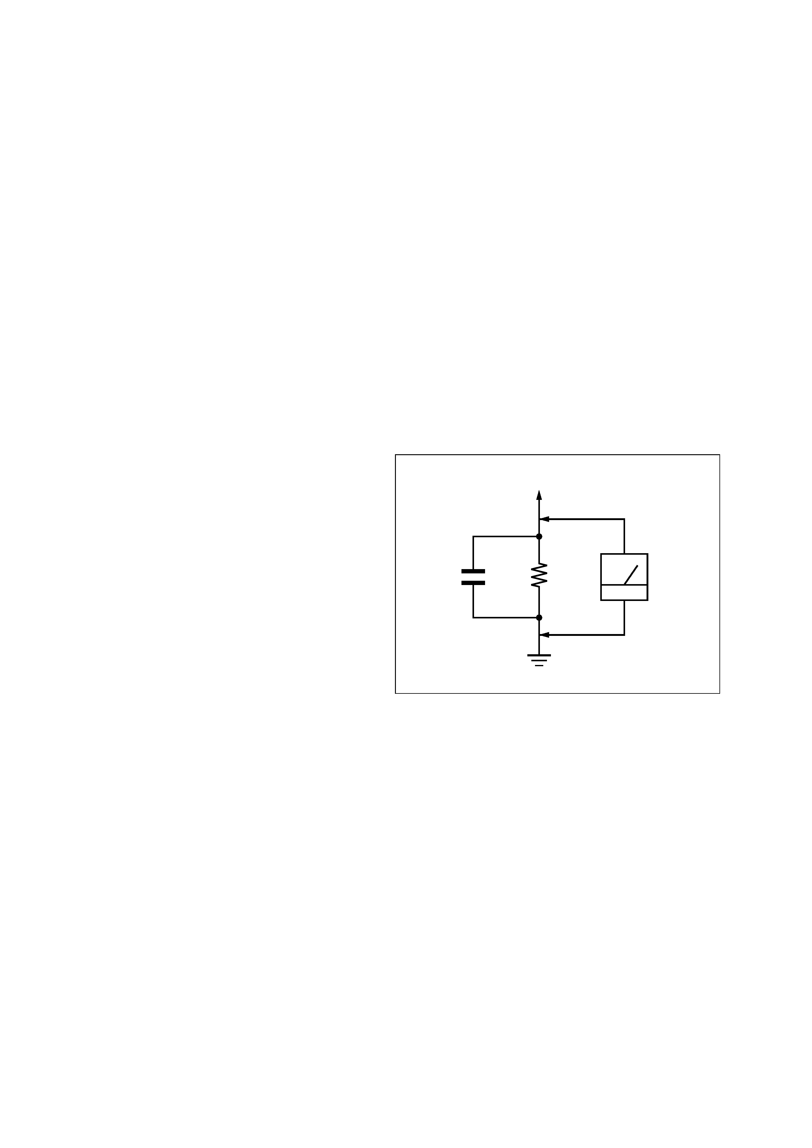
3. Measuring the voltage drop across a resistor by means of a
VOM or battery-operated AC voltmeter. The "limit" indica-
tion is 0.75 V, so analog meters must have an accurate low-
voltage scale. The Simpson 250 and Sanwa SH-63Trd are ex-
amples of a passive VOM that is suitable. Nearly all battery
operated digital multimeters that have a 2 V AC range are suit-
able. (See Fig. A)
Fig. A.
Using an AC voltmeter to check AC leakage.
1.5 k
0.15
µF
AC
voltmeter
(0.75 V)
To Exposed Metal
Parts on Set
Earth Ground
Notes on chip component replacement
· Never reuse a disconnected chip component.
· Notice that the minus side of a tantalum capacitor may be dam-
aged by heat.
3
SECTION 1
SERVICING NOTES
The laser diode in the optical pick-up block may suffer electro-
static break-down because of the potential difference generated
by the charged electrostatic load, etc. on clothing and the human
body.
During repair, pay attention to electrostatic break-down and also
use the procedure in the printed matter which is included in the
repair parts.
The flexible board is easily damaged and should be handled with
care.
NOTES ON LASER DIODE EMISSION CHECK
The laser beam on this model is concentrated so as to be focused
on the disc reflective surface by the objective lens in the optical
pick-up block. Therefore, when checking the laser diode emis-
sion, observe from more than 30 cm away from the objective lens.
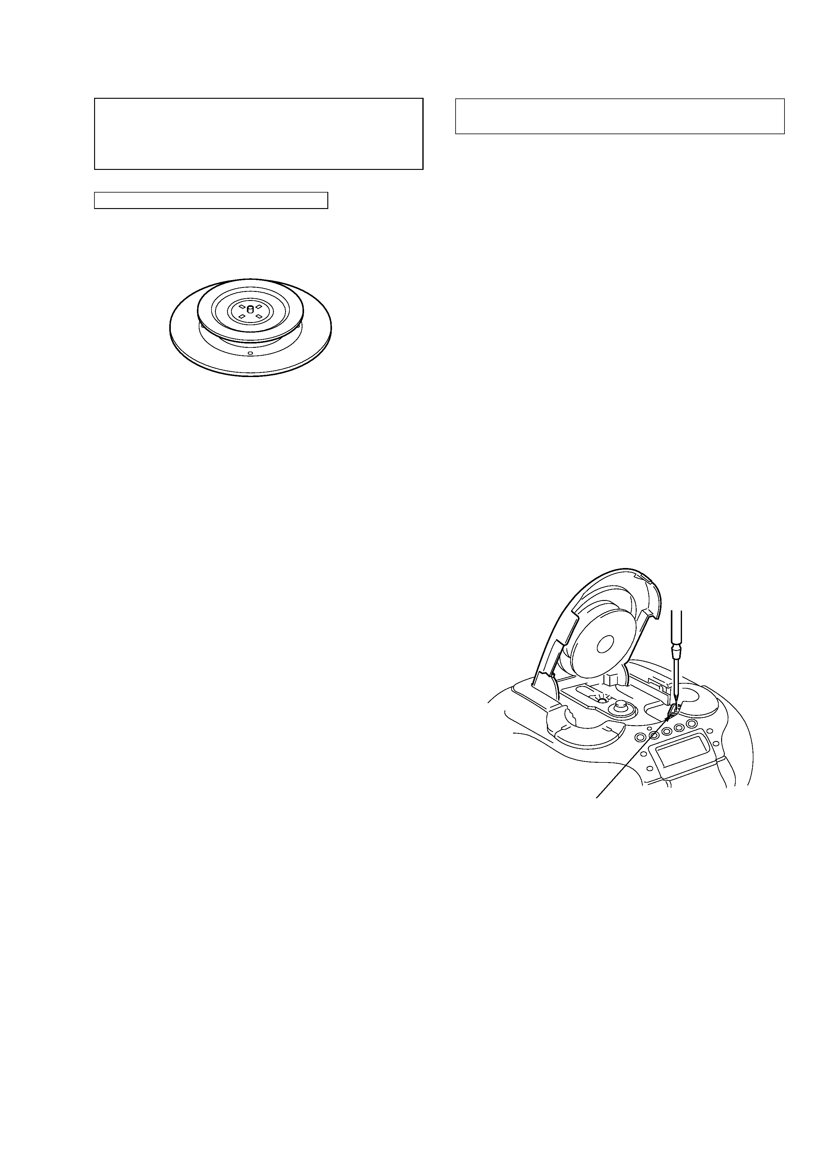
LASER DIODE AND FOCUS SEARCH OPERATION
CHECK
1. Turn POWER switch on with no disc inserted and make Func-
tion switch to CD position.
2. Open the lid for CD.
3. Turn on S701 as following figure.
4. Press the [
] (CD) button.
5. Confirm the laser diode emission while observing the object-
ing lens. When there is no emission, Auto Power Control cir-
cuit or Optical Pick-up is broken.
Objective lens moves up and down three times for the focus
search.
NOTES ON HANDLING THE OPTICAL PICK-UP
BLOCK OR BASE UNIT
S701
CAUTION
Use of controls or adjustments or performance of procedures
other than those specified herein may result in hazardous ra-
diation exposure.
CHUCK PLATE JIG ON REPAIRING
On repairing CD section, playing a disc without the CD lid, use
Chuck Plate Jig.
· Code number of Chuck Plate Jig: X-4918-255-1
u
4
MODEL TYPE IDENTIFICATION
In this set, the routing of speaker lead wires and the boards have been changed in the midway of production, and the set is grouped into the
following four types depending on the specifications.
TYPE A: Original model.
TYPE B: To the original model, the routing of speaker lead wires is changed.
TYPE C: To the type B, the print patterns of board are changed.
TYPE D: To the type C, the shapes of boards are changed.
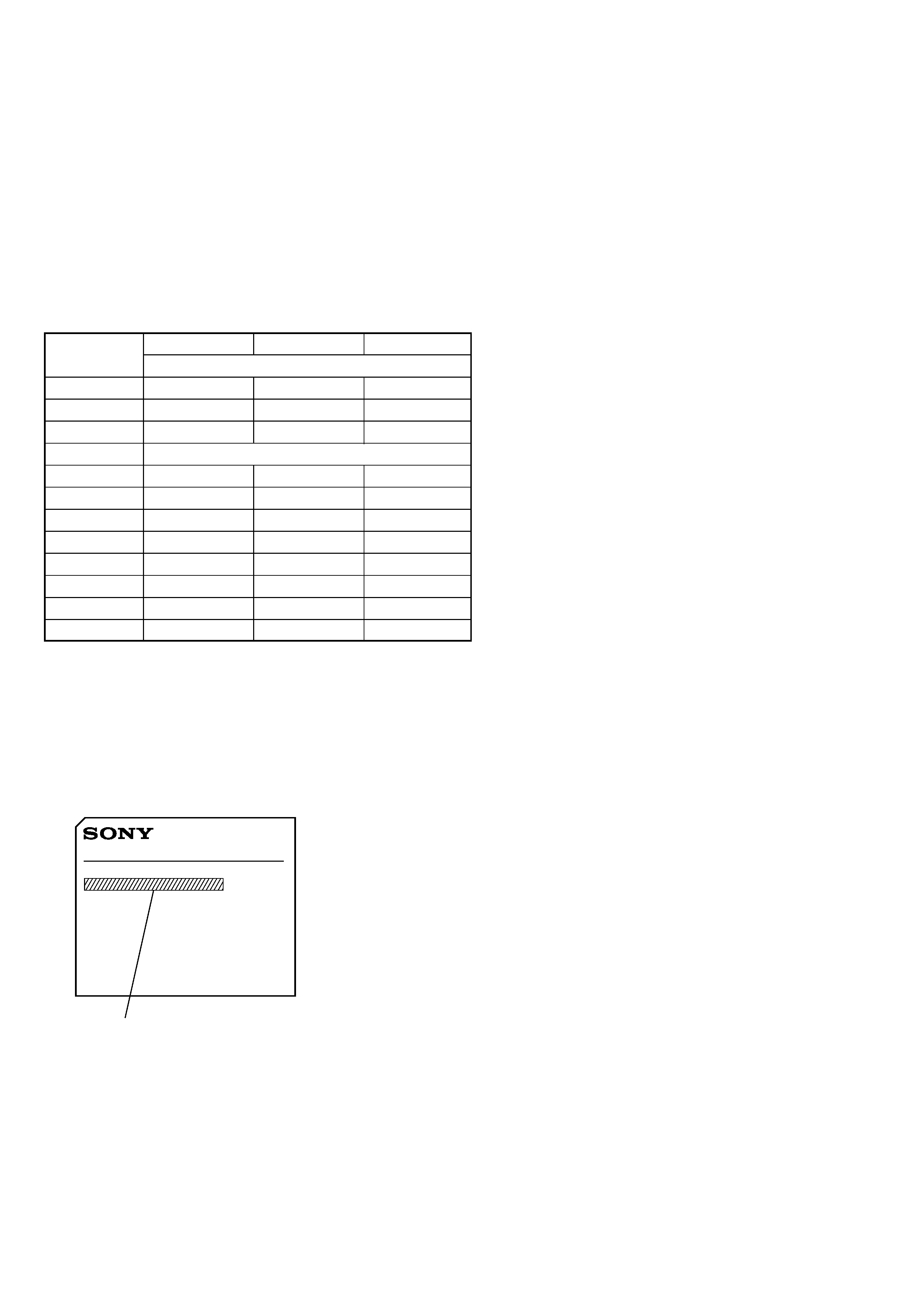
· Model Type Discrimination
Identify each type from the part number printed on each board by referring to the following table.
Also, each board is common to type A and type B, but routing of speaker lead wires is different. For details of different places, refer to "6.
Diagrams 6-10. Printed Wiring Boards MAIN/POWER SUPPLY Section (Type A, B) " (page 42, location A-1 and B-1).
Type A, B
Type C
Type D
Board
Part No.
BATT (+)
1-675-297-11
1-675-297-12
1-677-315-11
BATT ()
1-675-298-11
1-675-298-12
1-677-316-11
CD
1-675-290-11
1-675-290-12
1-677-308-11
CD MOTOR
in common to all types
KEY 1
1-675-292-11
1-675-292-12
1-677-310-11
KEY 2
1-675-293-11
1-675-293-12
1-677-311-11
KEY 3
1-675-294-11
1-675-294-12
1-677-312-11
LCD
1-675-295-11
1-675-295-12
1-677-313-11
LED *1
998-11
998-12
319-11
MAIN
1-675-289-11
1-675-289-12
1-677-307-11
POWER
1-675-291-11
1-675-291-12
1-677-309-11
REC SW
1-675-296-11
1-675-296-12
1-677-314-11
*1) For the LED board, only the lower five digits of part number is printed.
· Precaution on Replacing the Boards
The supplied boards are all type D, and therefore if the board is replaced, use the board of type D only whichever model is serviced.
However, on the type D model, the number of pins of connectors that connect MAIN board to CD board, and MAIN board to POWER
board has been changed, and accordingly the type D is not interchangeable with type A, B, and C respectively.
Therefore, if even one of MAIN, CD, and POWER boards is replaced, replace all three boards simultaneously.
MODEL IDENTIFICATION
MODEL NO.
CFD-E55
US, Canadian, E (AC 120V area),
Mexican models: AC: 120 V 60 Hz 17 W
Singapore, Argentine,
Australian models: AC: 230 V - 50 Hz 17 W
5
SECTION 2
GENERAL
This section is extracted from
instruction manual.