MICROFILM
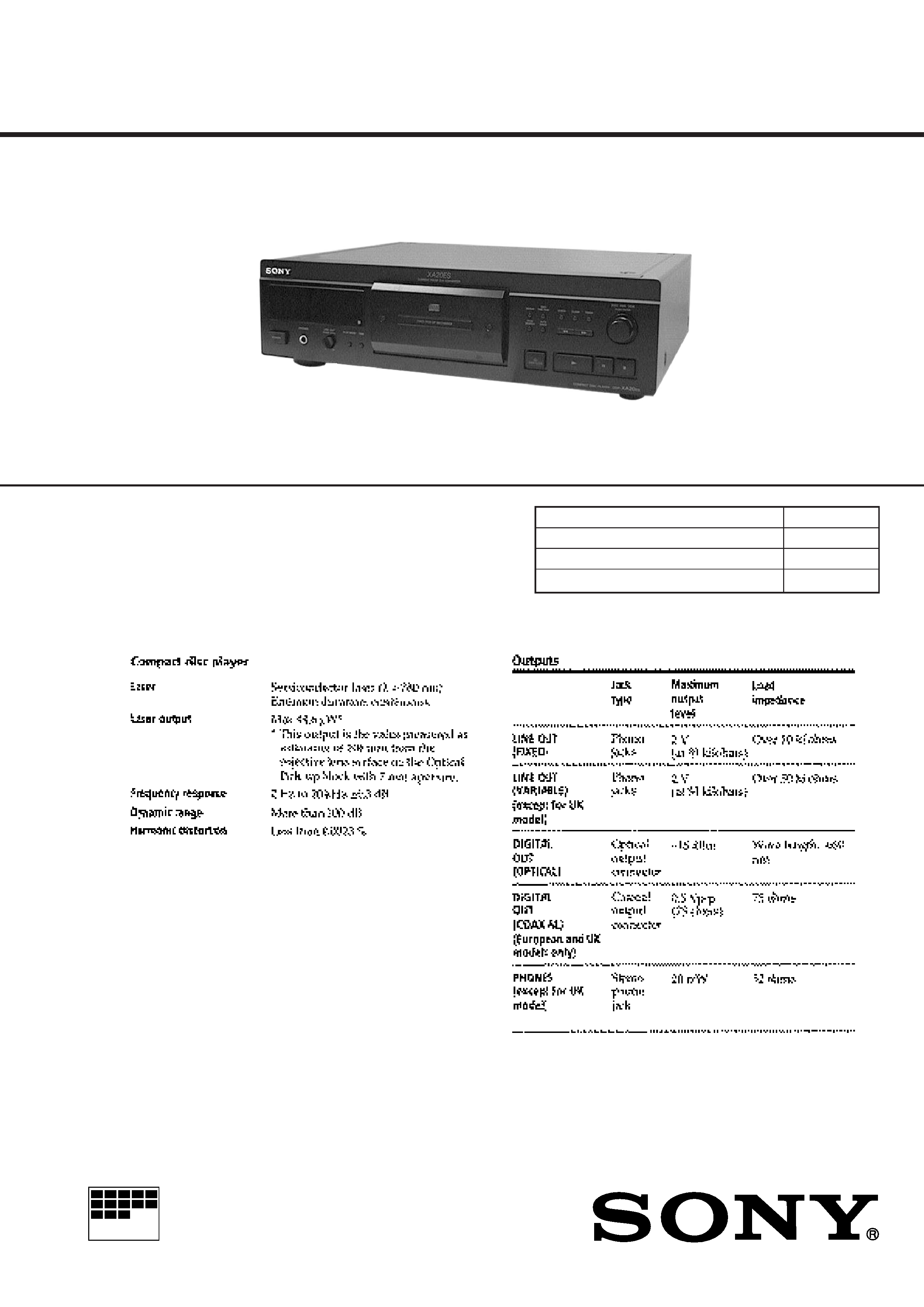
CDP-XA20ES
COMPACT DISC PLAYER
SERVICE MANUAL
US Model
Canadian Model
AEP Model
UK Model
E Model
Photo: Black
EXCEPT UK
SPECIFICATIONS
Model Name Using Similar Mechanism
NEW
CD Mechanism Type
CDM36B-14C
Base Unit Type
BU-14C
Optical Pick-up Type
KSS-213B
Continued on next page
2
TABLE OF CONTENTS
1.
SERVICING NOTES
1-1.
How to Open the Disc Tray When Power Switch
Turns Off .......................................................................... 4
1-2.
Preparation for Adjustment and Measurement ................ 4
2.
GENERAL ................................................................... 5
3.
DISASSEMBLY .......................................................... 6
4.
TEST MODE
4-1.
AF Mode .......................................................................... 11
4-2.
ADJ Mode ....................................................................... 12
5.
ELECTRICAL ADJUSTMENTS .......................... 13
6.
DIAGRAMS
6-1.
IC Pin Function Description ............................................ 15
6-2.
Block Diagram ................................................................. 21
6-3.
Printed Wiring Boards BD Section ............................. 24
6-4.
Schematic Diagram -- BD Section -- ............................ 27
6-5.
Schematic Diagram -- MAIN Section -- ....................... 30
6-6.
Printed Wiring Boards -- MAIN Section -- ................... 33
6-7.
Schematic Diagram -- POWER Section -- .................... 35
6-8.
Printed Wiring Boards -- POWER Section -- ............... 37
6-9.
Printed Wiring Boards -- PANEL Section -- ................. 39
6-10. Schematic Diagram -- PANEL Section -- ..................... 41
7.
EXPLODED VIEWS ................................................. 47
8.
ELECTRICAL PARTS LIST .................................. 52
SAFETY-RELATED COMPONENT WARNING!!
COMPONENTS IDENTIFIED BY MARK
! OR DOTTED
LINE WITH MARK
! ON THE SCHEMATIC DIAGRAMS
AND IN THE PARTS LIST ARE CRITICAL TO SAFE
OPERATION. REPLACE THESE COMPONENTS WITH
SONY PARTS WHOSE PART NUMBERS APPEAR AS
SHOWN IN THIS MANUAL OR IN SUPPLEMENTS PUB-
LISHED BY SONY.
MODEL IDENTIFICATION
BACK PANEL
4-991-138-
AEP Model
: 0
UK Model
: 1
Singapore Model : 2
US Model
: 3
Canadian Model : 4
ATTENTION AU COMPOSANT AYANT RAPPORT
À LA SÉCURITÉ!
LES COMPOSANTS IDENTIFIÉS PAR UNE MARQUE
!
SUR LES DIAGRAMMES SCHÉMATIQUES ET LA LISTE
DES PIÈCES SONT CRITIQUES POUR LA SÉCURITÉ
DE FONCTIONNEMENT. NE REMPLACER CES COM-
POSANTS QUE PAR DES PIÈCES SONY DONT LES
NUMÉROS SONT DONNÉS DANS CE MANUEL OU
DANS LES SUPPLÉMENTS PUBLIÉS PAR SONY.
3
NOTES ON HANDLING THE OPTICAL PICK-UP
BLOCK OR BASE UNIT
The laser diode in the optical pick-up block may suffer electro-
static break-down because of the potential difference generated
by the charged electrostatic load, etc. on clothing and the human
body.
During repair, pay attention to electrostatic break-down and also
use the procedure in the printed matter which is included in the
repair parts.
The flexible board is easily damaged and should be handled with
care.
NOTES ON LASER DIODE EMISSION CHECK
The laser beam on this model is concentrated so as to be focused
on the disc reflective surface by the objective lens in the optical
pick-up block. Therefore, when checking the laser diode emis-
sion, observe from more than 30 cm away from the objective lens.
Notes on chip component replacement
· Never reuse a disconnected chip component.
· Notice that the minus side of a tantalum capacitor may be dam-
aged by heat.
Flexible Circuit Board Repairing
· Keep the temperature of the soldering iron around 270 °C dur-
ing repairing.
· Do not touch the soldering iron on the same conductor of the
circuit board (within 3 times).
· Be careful not to apply force on the conductor when soldering
or unsoldering.
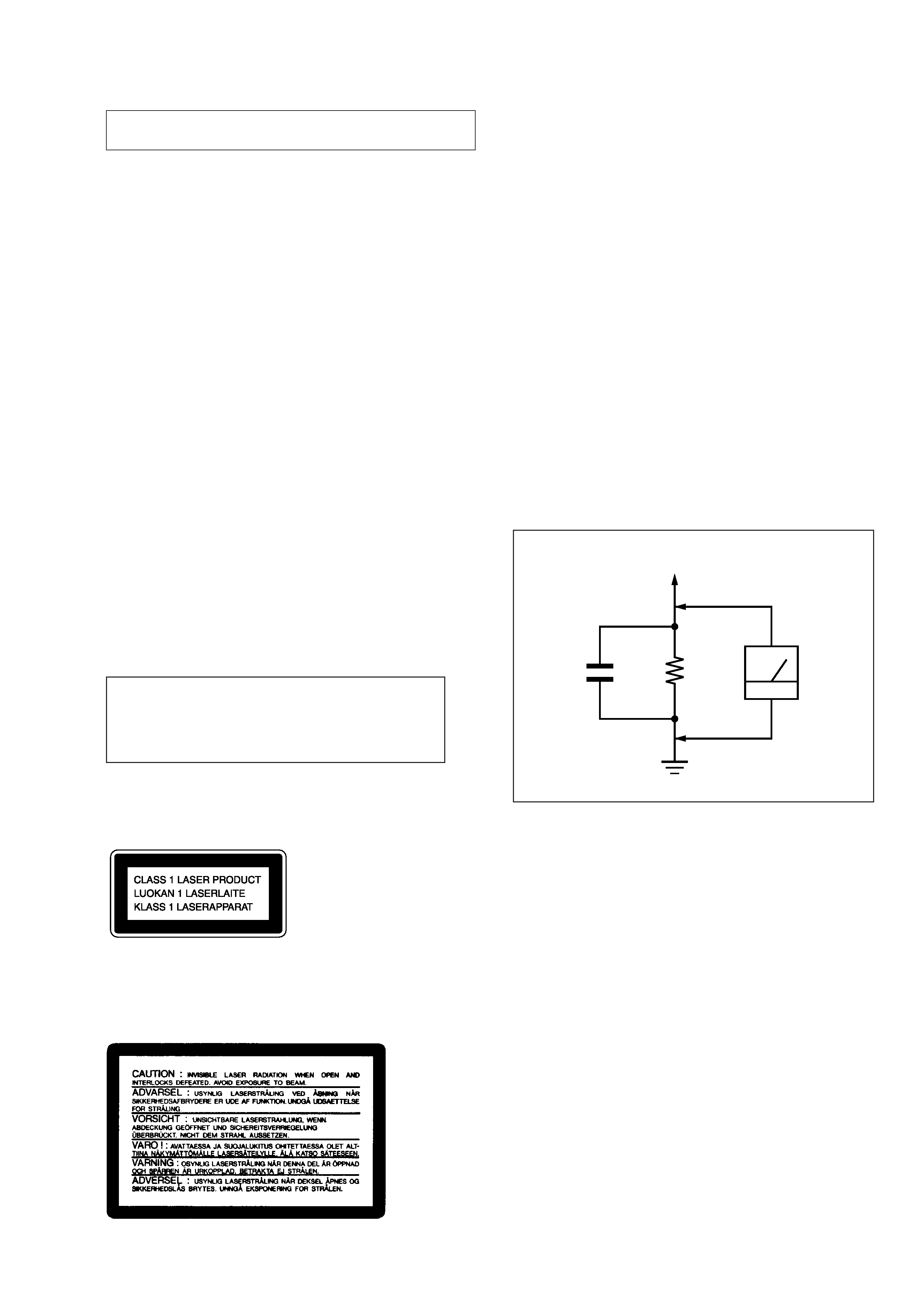
This appliance is classified as a CLASS 1 LASER product.
The CLASS 1 LASER PRODUCT MARKING is located on
the rear exterior.
Laser component in this product is capable of emitting radiation
exceeding the limit for Class 1.
The following caution label is located inside the unit.
CAUTION
Use of controls or adjustments or performance of
procedures other than those specified herein may
result in hazardous radiation exposure.
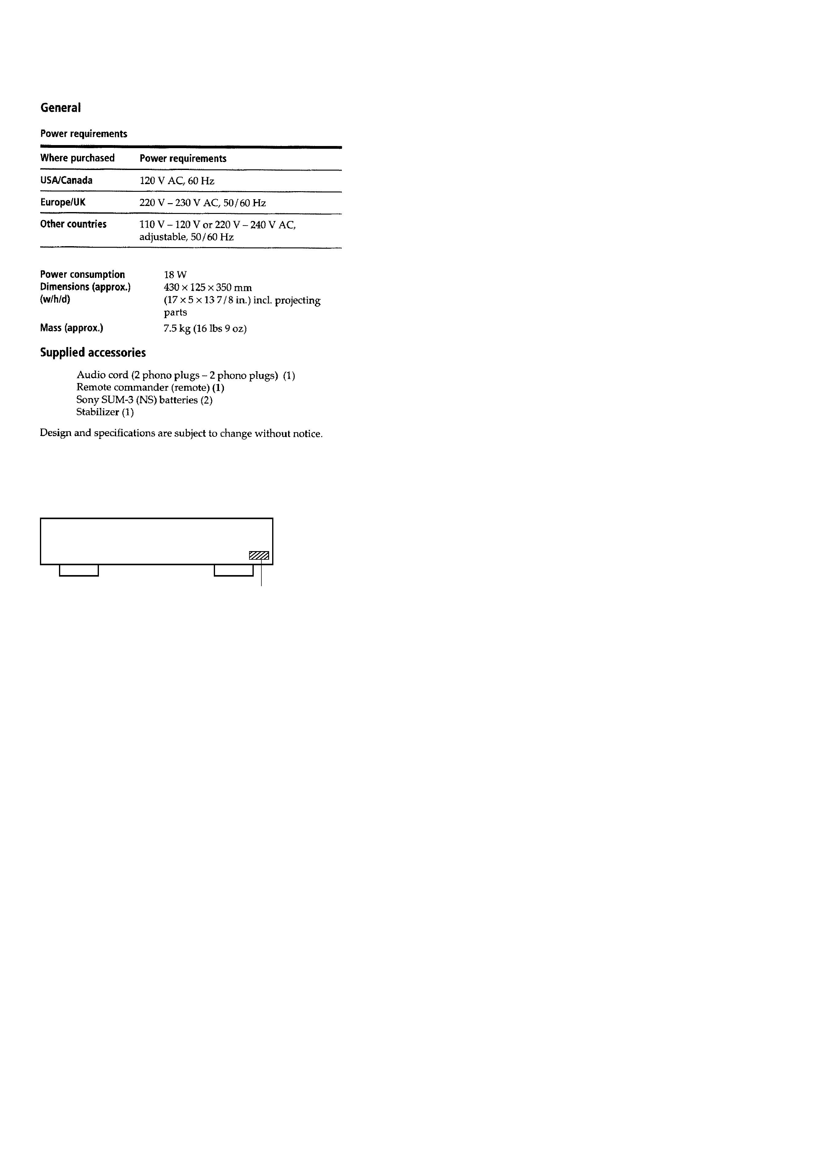
SAFETY CHECK-OUT
After correcting the original service problem, perform the follow-
ing safety check before releasing the set to the customer:
Check the antenna terminals, metal trim, "metallized" knobs,
screws, and all other exposed metal parts for AC leakage. Check
leakage as described below.
LEAKAGE TEST
The AC leakage from any exposed metal part to earth ground and
from all exposed metal parts to any exposed metal part having a
return to chassis, must not exceed 0.5 mA (500 microampers).
Leakage current can be measured by any one of three methods.
1. A commercial leakage tester, such as the Simpson 229 or RCA
WT-540A. Follow the manufacturers' instructions to use these
instruments.
2. A battery-operated AC milliammeter. The Data Precision 245
digital multimeter is suitable for this job.
3. Measuring the voltage drop across a resistor by means of a
VOM or battery-operated AC voltmeter. The "limit" indica-
tion is 0.75 V, so analog meters must have an accurate low-
voltage scale. The Simpson 250 and Sanwa SH-63Trd are ex-
amples of a passive VOM that is suitable. Nearly all battery
operated digital multimeters that have a 2 V AC range are suit-
able. (See Fig. A)
1.5 k
0.15
µF
AC
voltmeter
(0.75 V)
To Exposed Metal
Parts on Set
Earth Ground
Fig. A.
Using an AC voltmeter to check AC leakage.
4
SECTION 1
SERVICING NOTES
1-2.
PREPARATION FOR ADJUSTMENT AND
MEASUREMENT
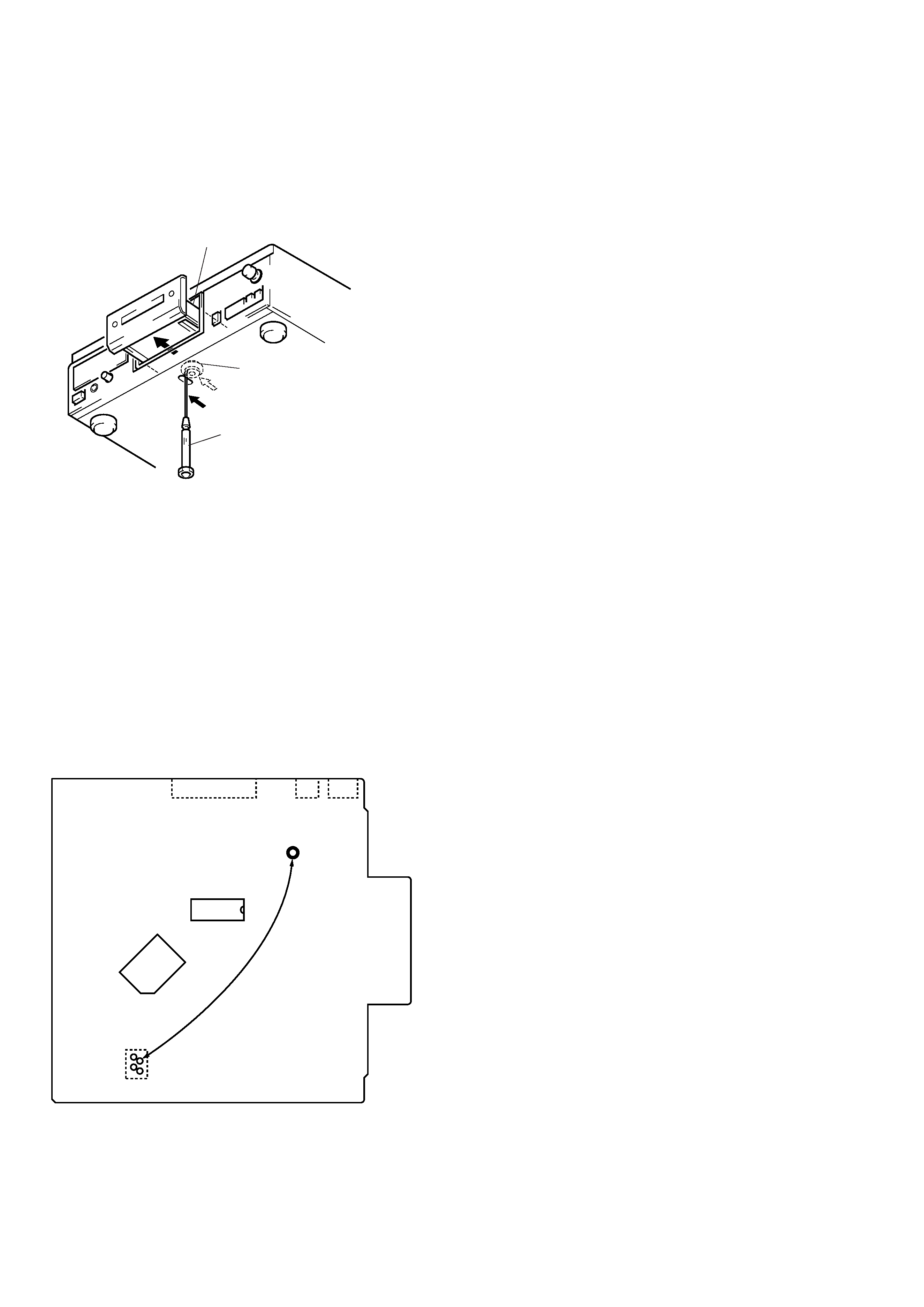
Perform connecting the IC361 pin 2 of BD board to the line of
+5V because this unit does not work without the stabilizer struc-
turally.
Connecting Location:
[BD BOARD] Side B
1-1.
HOW TO OPEN THE DISC TRAY WHEN
POWER SWITCH TURNS OFF
1 Insert a tapering driver into the aperture of the unit bottom,
and move the limiter (LEVER) to direction of the arrow A.
2 Pull the tray to direction fo the arrow B.
* To close the disc tray, move the driver in
the reverse direction (to IN direction).
tray
tapering driber
Limiter (LEVER)
A
B
IC361
IC351
TP (VCC)
IC102
CN102
CN103 CN105
1
2
3
4
5
SECTION 2
GENERAL
This section is extracted
from instruction manual.
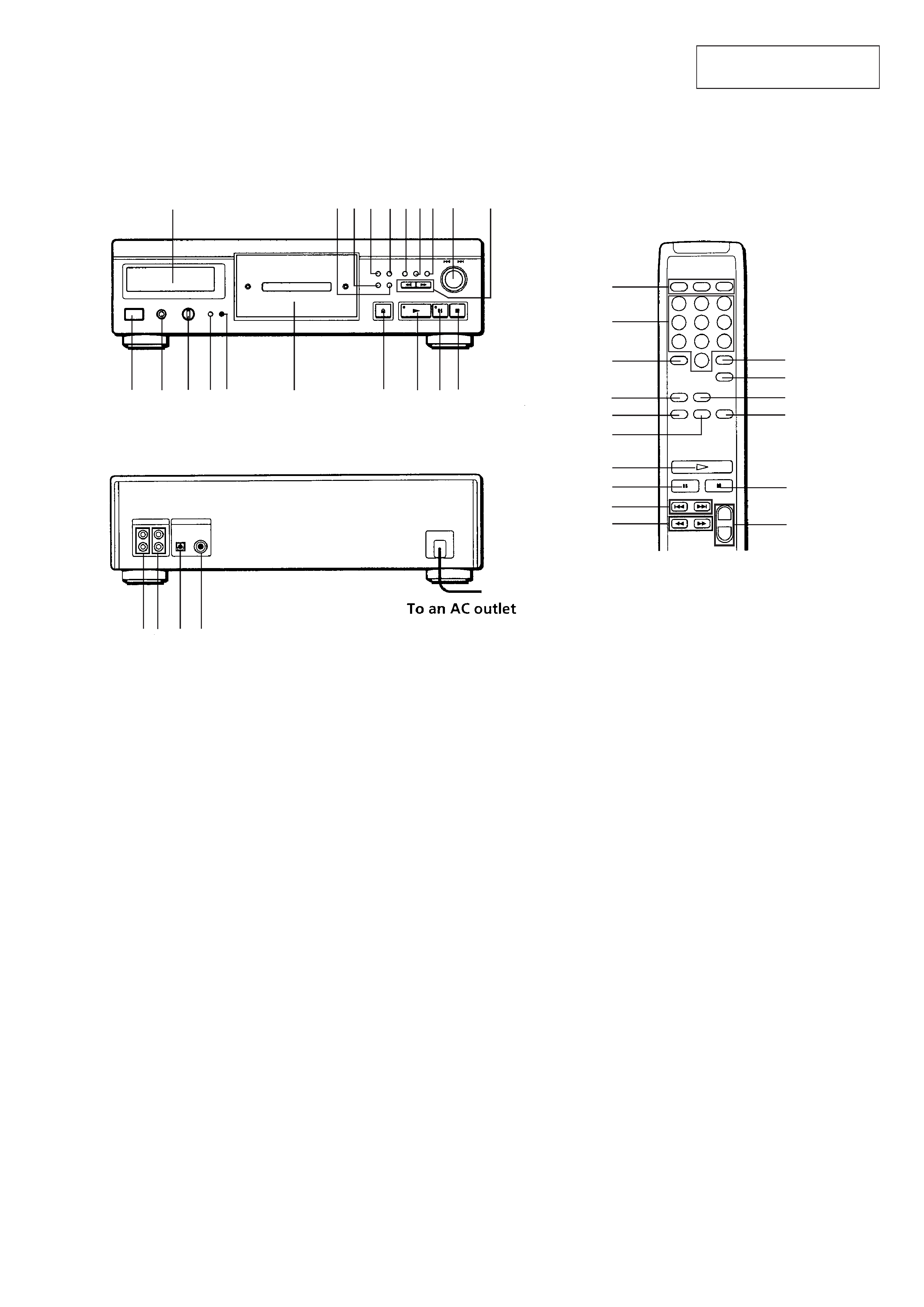
Location of Controls
· FRONT PANEL
@º
!¶ !§!!¢!£
!¡
!TM
!·
!ª
8
6
1
23
5
4
7
9 0
@¡@TM @£ @¢
@§
@¶
@
5
!¶
@ª
0
!¢
!
@·
!£
12
3
45
6
78
9
10
+
1 POWER Switch
2 PHONES jack (EXCEPT UK)
3 LINE OUT/PHONE LEVEL control (EXCEPT UK)
4 PLAY MODE button
5 TIME button
6 Disc tray
7 § OPEN/CLOSE button
8 ( (play) button
9 P (pause) button
0 p (stop) button
!¡ 0/) (manual search) buttons
!TM /± ( AMS*) control
!£ FADER button
!¢ CLEAR (program clear) button
! CHECK (program check) button
!§ EDIT/TIME FADE button
!¶ REPEAT button
(CLEAR REPEAT button on the remote commander)
!· PEAK SEARCH button
!ª AUTO SPACE button
@º Display
@¡ LINE OUT FIXED jack
@TM LINE OUT VARIABLE jack (EXCEPT UK)
@£ DIGITAL OUT OPTICAL jack
@¢ DIGITAL OUT COAXIAL jack (AEP, UK)
@ Play mode buttons
CONTINUE button
SHUFFLE button
PROGRAM button
@§ Numeric buttons
@¶ >10 (over 10) button
@· DISPLAY ON/OFF button
@ª A~B button
#º LINE OUT LEVEL +/ buttons
* AMS is the abbreviation of Automatic Music Sensor.
· REMOTE COMMANDER
8
9
!¡
!TM
·
·
·
·
·
·
·
··
·
· REAR PANEL
·
··
· · · · ·
·
·
·
#º
·
·
··
·
·
·
·