SERVICE MANUAL
COMPACT DISC PLAYER
AEP Model
UK Model
E Model
Australian Model
SPECIFICATIONS
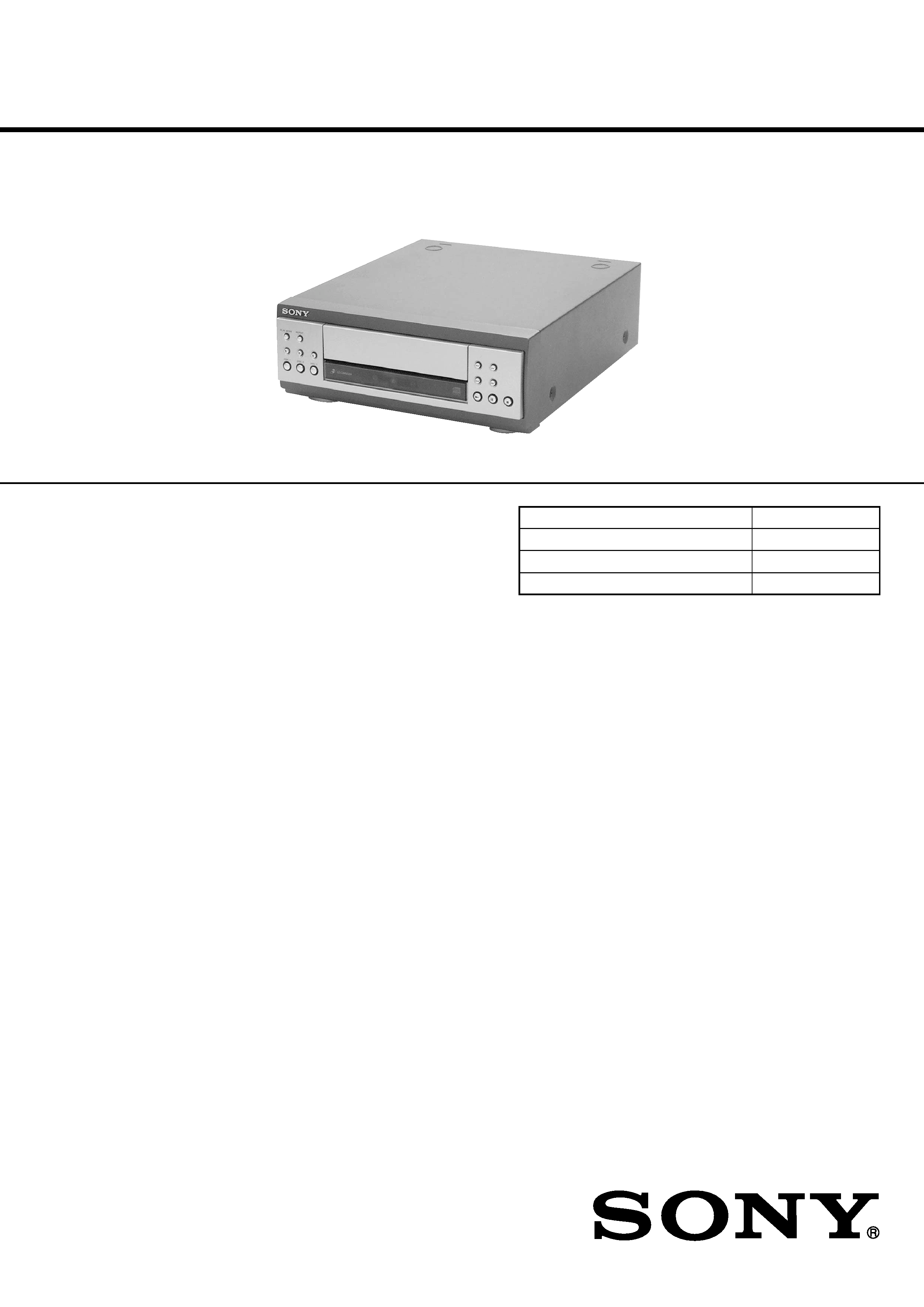
CDP-S3
Ver 1.0 2001.04
CDP-S3 is the CD player section
in MHC-S7AV or MHC-S3.
Model Name Using Similar Mechanism
NEW
CD Mechanism Type
CDM63B-30BD60
Base Unit Name
BU-30BD60
Optical Pick-up Name
OP Assy (A-MAX.3)
System
Compact disc and digital
audio system
Laser
Semiconductor laser
(
=780 nm)
Emission duration:
continuous
Frequency response
2 Hz 20 kHz (
±0.5 dB)
Signal-to-noise ratio
More than 90 dB
Dynamic range
More than 90 dB
OPTICAL OUT
(Square optical connector jack, rear panel)
Dimensions (w/h/d)
Approx. 280 x 108 x 330 mm
Mass
Approx. 2.7 kg
Design and specifications are subject to change
without notice.
9-873-831-11
Sony Corporation
2001D0500-1
Home Audio Company
C
2001.4
Shinagawa Tec Service Manual Production Group
2
CDP-S3
SAFETY-RELATED COMPONENT WARNING!!
COMPONENTS IDENTIFIED BY MARK 0 OR DOTTED
LINE WITH MARK 0 ON THE SCHEMATIC DIAGRAMS
AND IN THE PARTS LIST ARE CRITICAL TO SAFE
OPERATION. REPLACE THESE COMPONENTS WITH
SONY PARTS WHOSE PART NUMBERS APPEAR AS
SHOWN IN THIS MANUAL OR IN SUPPLEMENTS PUB-
LISHED BY SONY.
The laser diode in the optical pick-up block may suffer electro-
static break-down because of the potential difference generated
by the charged electrostatic load, etc. on clothing and the human
body.
During repair, pay attention to electrostatic break-down and also
use the procedure in the printed matter which is included in the
repair parts.
The flexible board is easily damaged and should be handled with
care.
NOTES ON LASER DIODE EMISSION CHECK
The laser beam on this model is concentrated so as to be focused
on the disc reflective surface by the objective lens in the optical
pick-up block. Therefore, when checking the laser diode emis-
sion, observe from more than 30 cm away from the objective lens.
LASER DIODE AND FOCUS SEARCH OPERATION
CHECK
Carry out the "S curve check" in "CD section adjustment" and
check that the S curve waveforms is output three times.
Notes on chip component replacement
· Never reuse a disconnected chip component.
· Notice that the minus side of a tantalum capacitor may be dam-
aged by heat.
Flexible Circuit Board Repairing
· Keep the temperature of the soldering iron around 270 °C dur-
ing repairing.
· Do not touch the soldering iron on the same conductor of the
circuit board. (within 3 times)
· Be careful not to apply force on the conductor when soldering
or unsoldering.
NOTES ON HANDLING THE OPTICAL PICK-UP
BLOCK OR BASE UNIT
CAUTION
Use of controls or adjustments or performance of procedures
other than those specified herein may result in hazardous ra-
diation exposure.
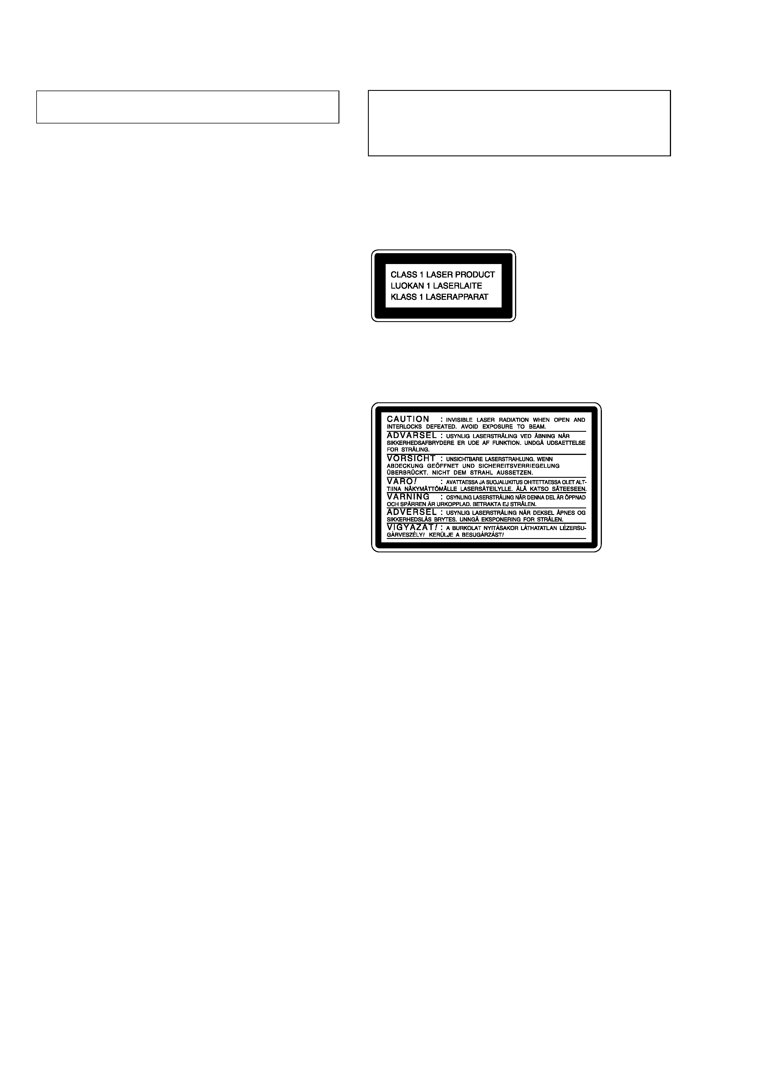
This appliance is classified as a CLASS 1 LASER product.
The CLASS 1 LASER PRODUCT MARKING is located on
the rear exterior.
Laser component in this product is capable of emitting radiation
exceeding the limit for Class 1.
The following caution label is located inside the unit.

3
CDP-S3
TABLE OF CONTENTS
1.
SERVICING NOTES ............................................... 4
2.
GENERAL ................................................................... 5
3.
DISASSEMBLY
3-1. Disassembly Flow ...........................................................
6
3-2. Cover ...............................................................................
7
3-3. CD Mechanism Deck (CDM63B-30BD60) ...................
7
3-4. MAIN Board ...................................................................
8
3-5. Front Panel Section .........................................................
8
3-6. PANEL (L) Board, PANEL (R) Board ...........................
9
3-7. Lid (CD) ..........................................................................
9
4.
TEST MODE .............................................................. 10
5.
ELECTRICAL ADJUSTMENTS ......................... 11
6.
DIAGRAMS
6-1. Note for Printed Wiring Boards
and Schematic Diagrams ................................................ 12
6-2. Printed Wiring Board BD Section ........................... 14
6-3. Schematic Diagram BD Section ............................... 15
6-4. Printed Wiring Boards CD CHANGER Section ..... 16
6-5. Schematic Diagram CD CHANGER Section ......... 17
6-6. Printed Wiring Board MAIN Section ...................... 18
6-7. Schematic Diagram MAIN Section ......................... 19
6-8. Printed Wiring Boards PANEL Section .................. 20
6-9. Schematic Diagram PANEL Section ....................... 21
6-10. IC Pin Function Description ........................................... 24
7.
EXPLODED VIEWS
7-1. General Section ............................................................... 26
7-2. CD Mechanism Deck Section-1
(CDM63B-30BD60) ....................................................... 27
7-3. CD Mechanism Deck Section-2
(CDM63B-30BD60) ....................................................... 28
7-4. Base Unit Section (BU-30BD60) ................................... 29
8.
ELECTRICAL PARTS LIST ............................... 30
4
CDP-S3
SECTION 1
SERVICING NOTES
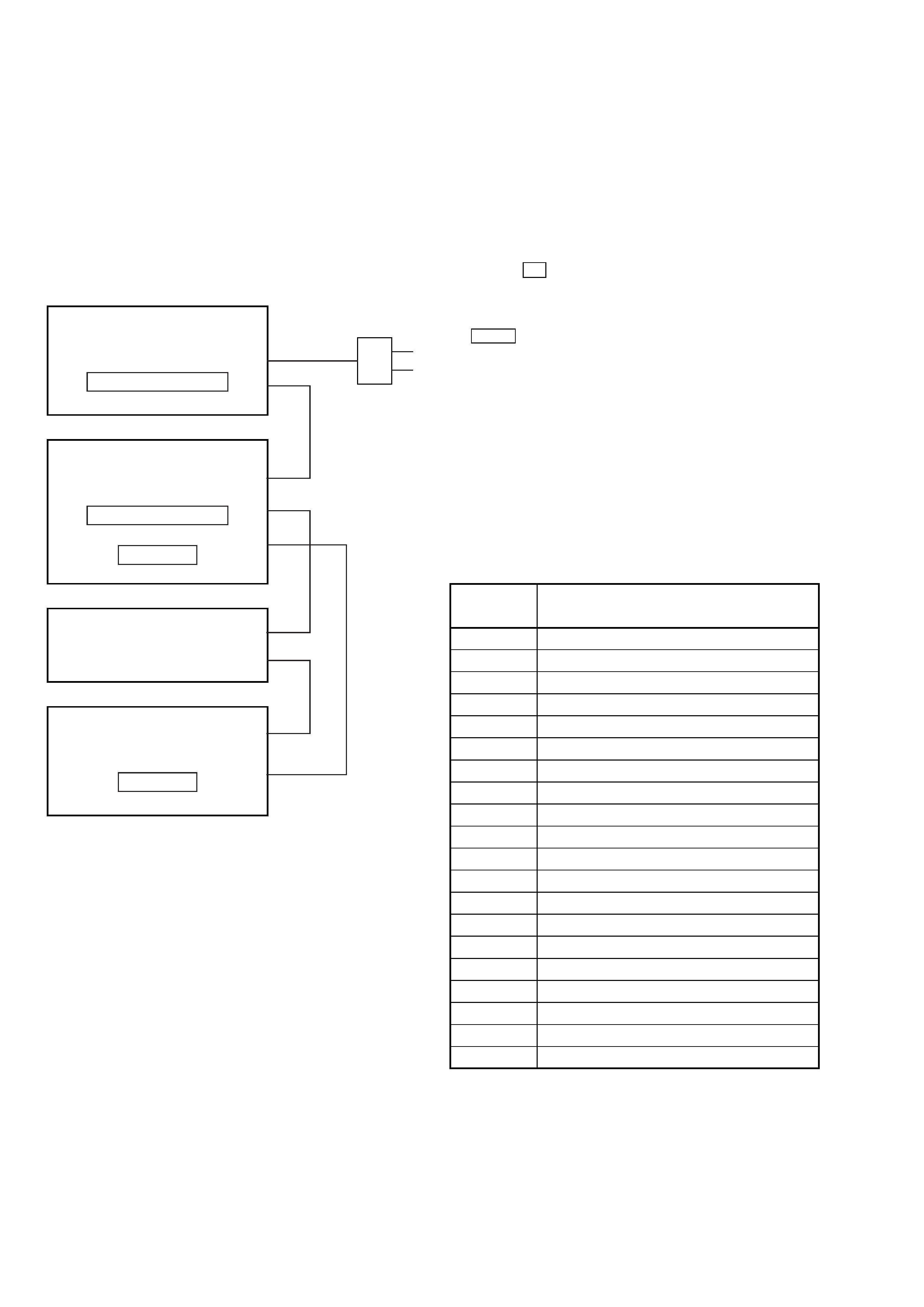
This set is a component of the MHC-S7AV or MHC-S3.
The MHC-S7AV or MHC-S3 system configuration is as shown
below, and therefore it does not operate normally unless all four
components are connected.
In performing the repair, connect all components with the system
cables.
Note: The precaution to the users is described on the label stuck on
the back panel (CD player) and in the troubleshooting section in
the Operation Manual.
System Configuration:
POWER SUPPLY
AC IN
TA
SYSTEM & CD
µcon
ST
CDP
TC
µcon
TC
DISPLAY
CD-TEXT TEST DISC
This unit is able to display the test data (character information)
written in the CD on its fluorescent indicator tube.
The CD-TEXT TEST DISC (TGCS-313:4-989-366-01) is used
for checking the display.
To check, perform the following procedure.
Checking Method:
1. Press the I/1 button to turn the power on, set the disc to the
disc table with the "test disc" label facing up, and chuck the
disc.
2. Press the [CD] button to set CD function, and press the
n N
button to playback the disc.
3. The following will be displayed on the liquid crystal display.
Display : 1KHZ/0DB/L R
4. Pressing the [--
] or [
+] button, select the track. The text
data of each track will be displayed.
For details of the displayed contents for each track, refer to "Table
1 : CD-TEXT TEST DISC TEXT Data Contents".
Restrictions in CD-TEXT Display
In this unit, some special characters will not be displayed prop-
erly. These will be displayed as a space or a character resembling
it.
Table 1 : CD-TEXT TEST DISC TEXT Data Contents
(TRACKS No. 1 to 20:Normal Characters)
1
1kHz/0dB/L&R
2
20Hz/0dB/L&R
3
40Hz/0dB/L&R
4
100Hz/0dB/L&R
5
200Hz/0dB/L&R
6
500Hz/0dB/L&R
7
1kHz/0dB/L&R
8
5kHz/0dB/L&R
9
7kHz/0dB/L&R
10
10kHz/0dB/L&R
11
16kHz/0dB/L&R
12
18kHz/0dB/L&R
13
20kHz/0dB/L&R
14
1kHz/0dB/L&R
15
1kHz/1dB/L&R
16
1kHz/3dB/L&R
17
1kHz/6dB/L&R
18
1kHz/10dB/L&R
19
1kHz/20dB/L&R
20
1kHz/60dB/L&R
TRACK
No.
Displayed Contents
Note: Track No. 21 to 99 are not displayed.
.>
5
CDP-S3
SECTION 2
GENERAL
This section is extracted from
instruction manual.
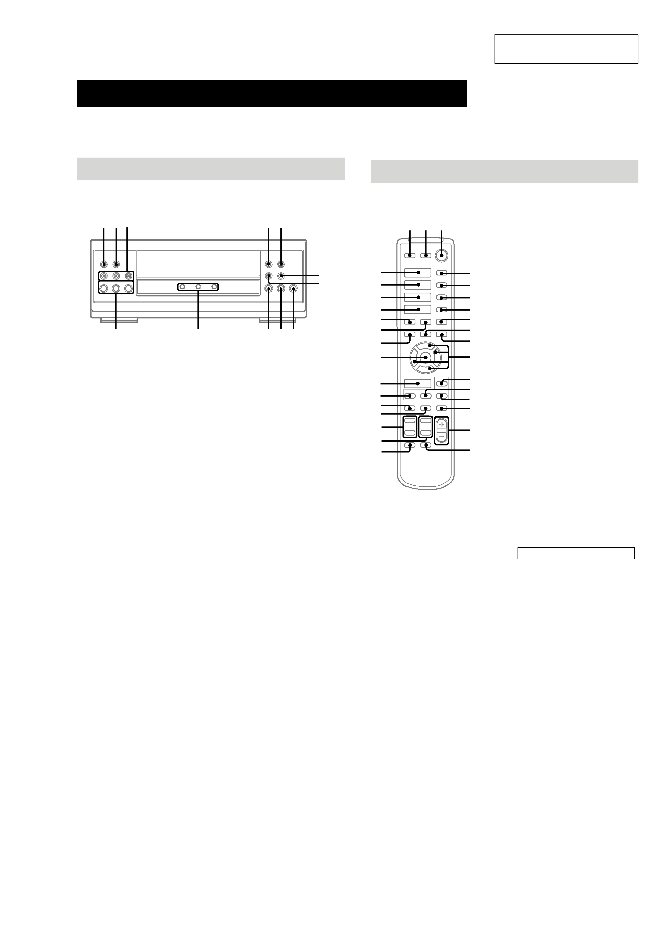
Parts Identification
The items are arranged in alphabetical order.
Refer to the pages indicated in parentheses ( ) for details.
Main unit
mM
.
HS
x
>
1
2
3
wj wkwl
e; ea
es
ed
ef
eg
eh
ej
ek
DISC 13 ek (14, 15, 21)
DISC 13 indicators ej
DISC 13 Z (eject) wl (14)
PLAY MODE wj (14, 15, 21)
REPEAT wk (14)
N (play) eh (14, 15)
X (pause) eg (14)
x (stop) ef (14, 20)
. (go back) ed (14, 15, 21)
> (go forward) es (14, 15, 21)
m (rewind) e; (14)
M (fast forward) ea (14)
x
hH
H
hH
O
o
Pp
M
m
X
>
.
12 3
wg
qh
qa
wk
wj
wh
wa
4
5
6
7
qs
qf
qd
qg
8
9
q;
qk
ql
w;
qj
wd
ws
wf
es
ea
e;
wl
CD H es (14, 15)
CHECK 5 (15)
CLEAR 6 (15)
CLOCK/TIMER SELECT qj
(30)
CLOCK/TIMER SET qk (13, 21,
29)
DBFB qg (23)
DISPLAY ws (13, 16, 18, 29, 35)
D.SKIP 4 (14)
ENTER wg (10, 12, 13, 15, 17,
18, 21, 22, 2630)
EQ qd (27)
EQ ON/OFF qf (10, 28)
FUNCTION wf (10, 14, 15, 20,
21, 31)
GROOVE wa (23)
SET UP qs (10, 12, 26, 28, 29)
SLEEP 7 (29)
SUR wd (25)
TAPE A hH ea (19, 35)
TAPE B hH e; (19, 20, 35)
TUNER/BAND wl (17)
TUNING + 9 (17)
TUNING wh (17)
TV CH +/ ql
TV VOL +/ w;
TV @/1 2
TV/VIDEO 1
VOL +/ qh
BUTTON DESCRIPTIONS
@/1 (power) 3
X (pause) q;
x (stop) 8
. (go back) wk
> (go forward) wj
m (rewind) wh
M (fast forward) 9
O/o/P/p qa
Remote Control