1
CDP-EX100
SERVICE MANUAL
AEP Model
UK Model
E Model
Model Name Using Similar Mechanism
CDP-EX10
CD Mechanism Type
CDM28-5BD19
Base Unit Name
BU-5BD19
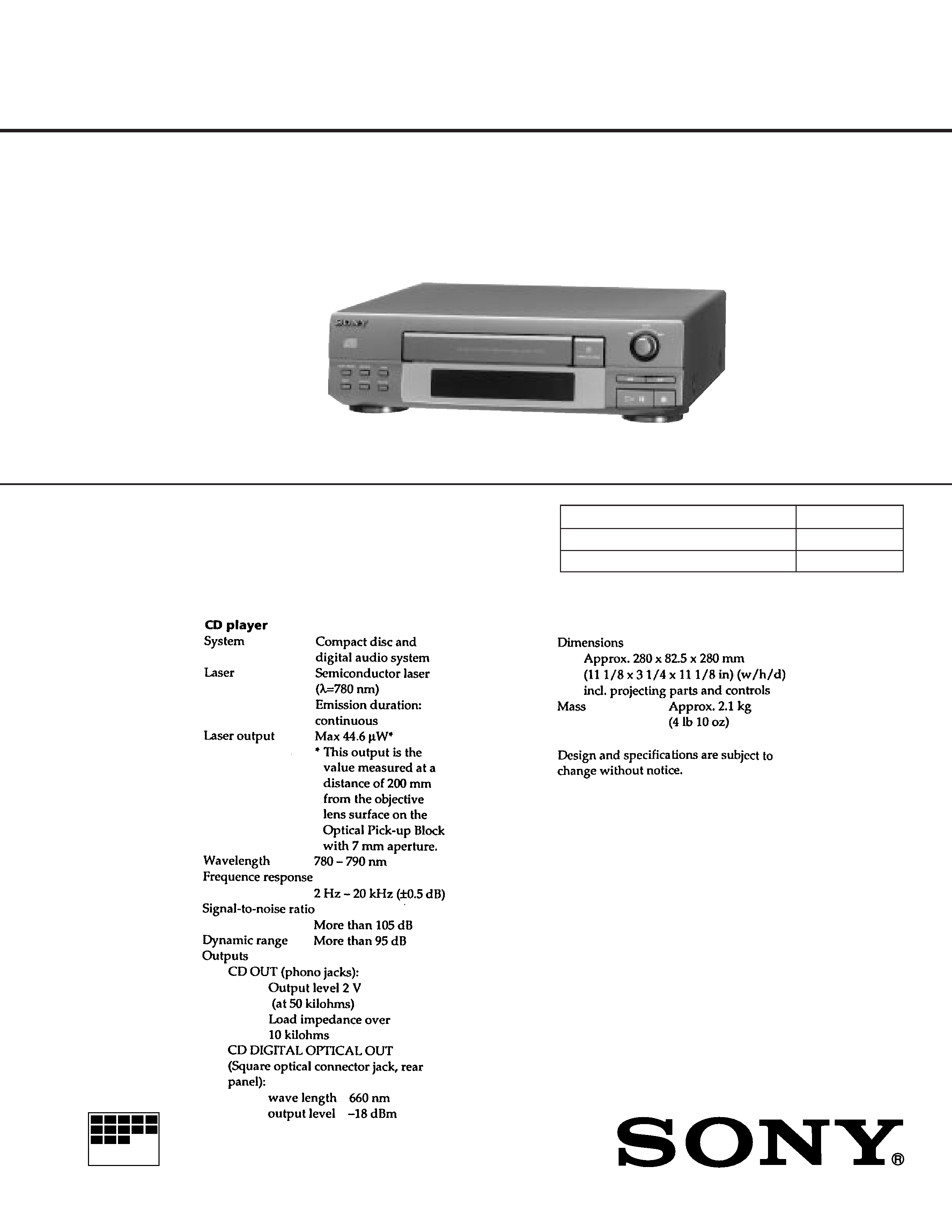
SPECIFICATIONS
COMPACT DISC PLAYER
MICROFILM
This set is the CD player section in
MHC-EX50/EX70AV/EX100AV.
2
The laser component in this product
is capable of emitting radiation
exceeding the limit for Class 1.
The following caution label is located inside of the unit.
SAFETY-RELATED COMPONENT WARNING!!
COMPONENTS IDENTIFIED BY MARK
! OR DOTTED LINE
WITH MARK
! ON THE SCHEMATIC DIAGRAMS AND IN THE
PARTS LIST ARE CRITICAL TO SAFE OPERATION. REPLACE
THESE COMPONENTS WITH SONY PARTS WHOSE PART
NUMBERS APPEAR AS SHOWN IN THIS MANUAL OR IN
SUPPLEMENTS PUBLISHED BY SONY.
TABLE OF CONTENTS
1. SERVICE NOTE .................................................................. 3
2. GENERAL ............................................................................. 4
3. DISASSEMBLY
3-1. Loading Panel .......................................................................... 4
3-2. MD Block ................................................................................ 5
3-3. Holder (BU) Assy .................................................................... 5
4. ELECTRICAL ADJUSTMENTS .................................... 6
5. DIAGRAMS
5-1. IC Pin Function ....................................................................... 8
5-2. Circuit Boards Location ........................................................ 10
5-3. Printed Wiring Board BD Section ................................... 11
5-4. Schematic Diagram BD Section ...................................... 13
5-5. Printed Wiring Boards Main Section .............................. 16
5-6. Schematic Diagram Main Section ................................... 19
6. EXPLODED VIEWS
6-1. Chassis Section ...................................................................... 26
6-2. Front Panel Section ............................................................... 27
6-3. CD Mechanism Section ......................................................... 28
6-4. Base Unit Section .................................................................. 29
7. ELECTRICAL PARTS LIST .......................................... 30
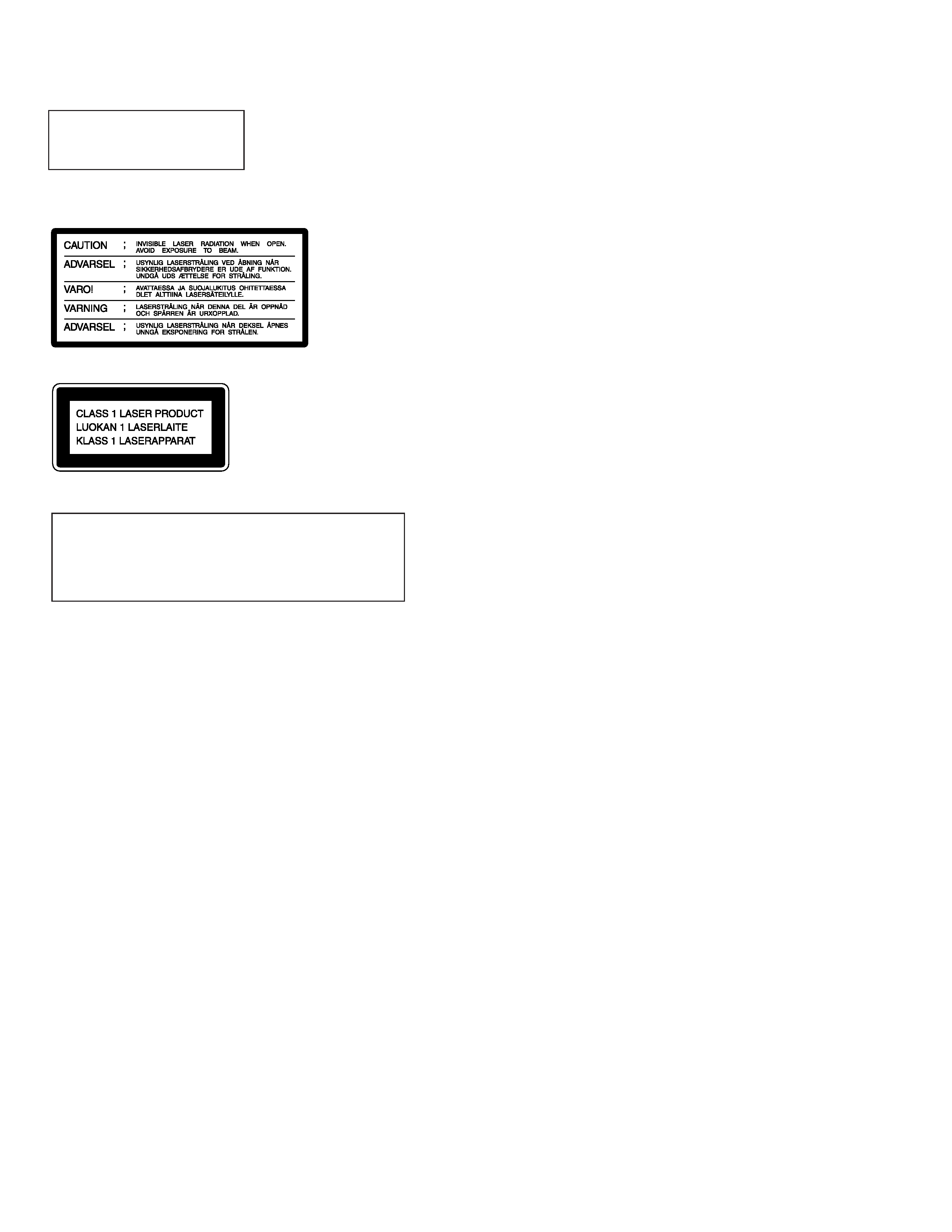
This appliance is classified
as a CLASS 1 LASER
product.
The CLASS 1 LASER
PRODUCT MARKING is
located on the rear exterior.
CAUTION
Use of controls or adjustments or performance of proce-
dures other than those specified herein may result in haz-
ardous radiation exposure.
Notes on Chip Component Replacement
· Never reuse a disconnected chip component.
· Notice that the minus side of a tantalum capacitor may be dam-
aged by heat.
NOTES ON HANDLING THE OPTICAL PICK-UP BLOCK OR
BASE UNIT
The laser diode in the optical pick-up block may suffer electrostatic
breakdown because of the potential difference generated by the
charged electrostatic load, etc. on clothing and the human body.
During repair, pay attention to electrostatic breakdown and also use
the procedure in the printed matter which is included in the repair
parts.
The flexible board is easily damaged and should be handled with
care.
NOTES ON LASER DIODE EMISSION CHECK
The laser beam on this model is concentrated so as to be focused on
the disc reflective surface by the objective lens in the optical pick-up
block. Therefore, when checking the laser diode emission, observe
from more than 30 cm away from the objective lens.
3
· FL tube/ KEY check mode
After to enter the power on, when
p button, TIME button and
) button are pressed at the same time, you will be check FL
tube.
Whenever press the above mentioned three buttons at the same
time, change to check mode of FL tube.
Under check mode of FL tube when any pressing button or turn
= AMS + button, change to KEY check mode.
To finish KEY check mode, press the above mentioned three
buttons at the same time.
All FL tube indicator light on
A segment pattern mode 1
A segment pattern mode 2
Finish the test mode
Note 1)
All FL tube light on mode is kept when three buttons which is
pressed to enter all FL tube light on mode, release at the same time.
If you will be release failure them, it is moved to KEY check mode
after all FL tube light on mode.
Note 2)
Under KEY check mode, every time and button pressed or
= AMS + button turned on, figure on " KEY= " of FL tube
is increased.
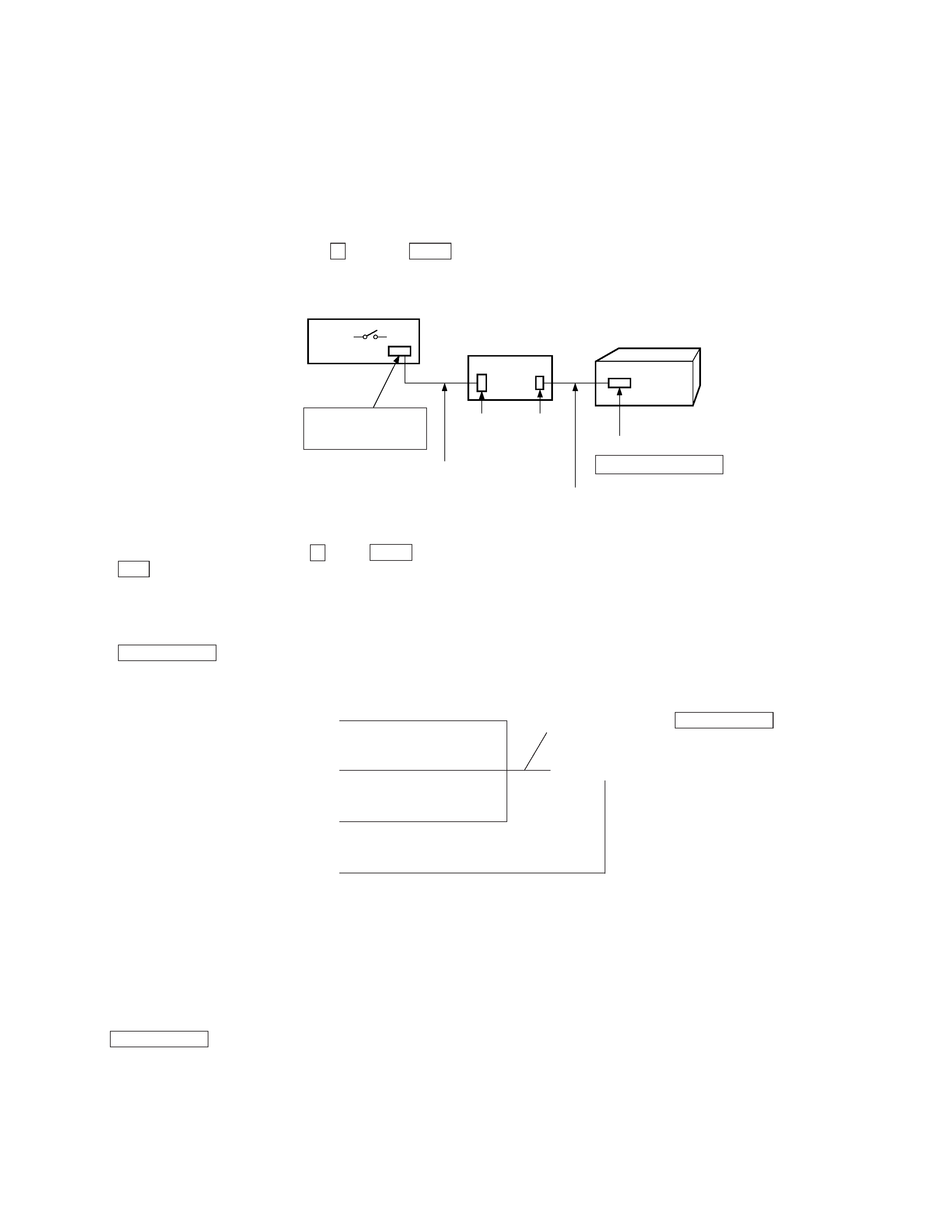
· How to operate with a single unit
Normally this set does not operate with a single unit.
When you must be mending, connect to other unit.
If the SYSTEM POWER switch of the amplifire is set to ON, the
power supply of the set is turned on.
In case of other unit is nothing, the service box (PFJ-1) and
exclusive jig (J-2501-078-A) are necessary to operate the set with
a single unit.
In case of above mentioned, press the
p button and TIME button
at the same time, to enter the power on.
SECTION 1
SERVICE NOTE
nn
n
(Press three buttons at the same time)
(Press three buttons at the same time)
(Press three buttons at the same time)
KEY check mode
(
Any pressing button or turn
= AMS + button.
9
(
(Press three buttons at the same time)
SERVICE BOX (PFJ-1)
POWER SW
FH-E939, 838, 737
CDP/TC
CN904
17P
CN902
7P
CORD WITH CONNECTOR 17P
(attached to PFJ-1)
JIG
(J-2501-078-A)
CORD WITH CONNECTOR 7P
(attached to set)
SET
CN301 7P
SYSTEM CONTROL
4
SECTION 2
GENERAL
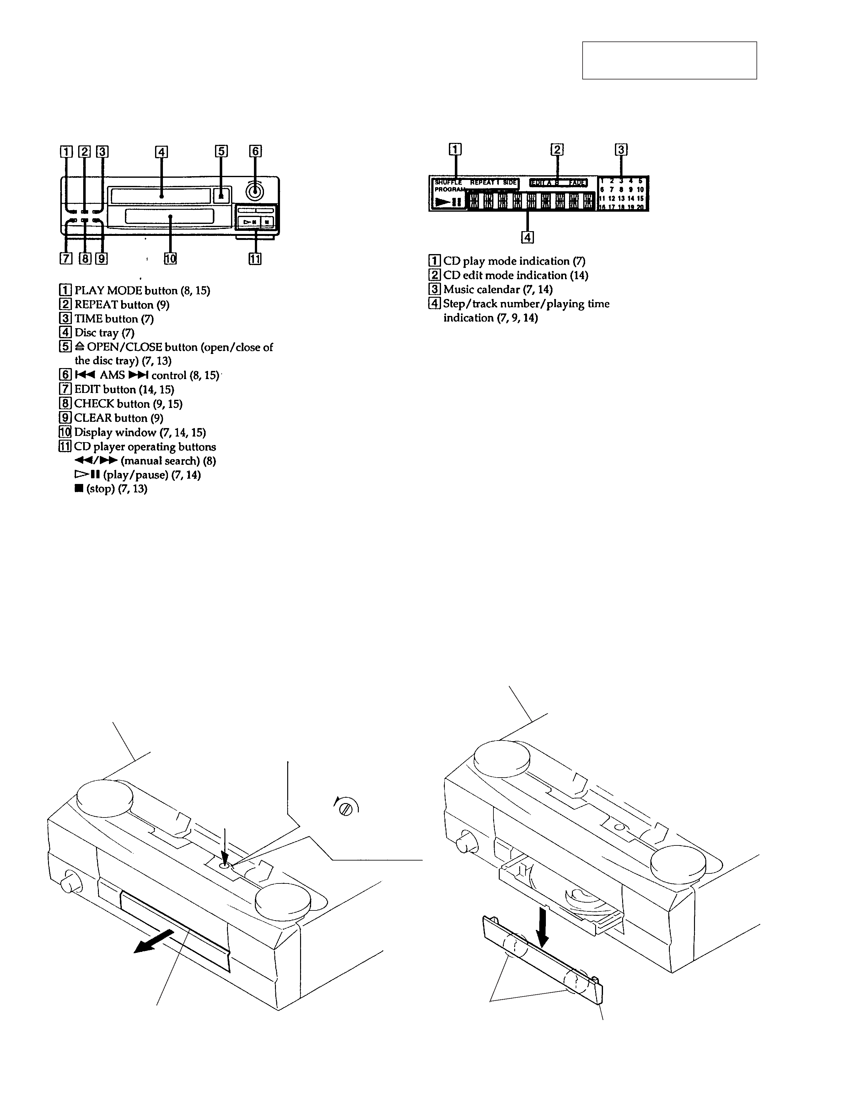
Front Panel
Display Window
SECTION 3
DISASSEMBLY
Note : Follow the disassembly procedure in the numerical order given.
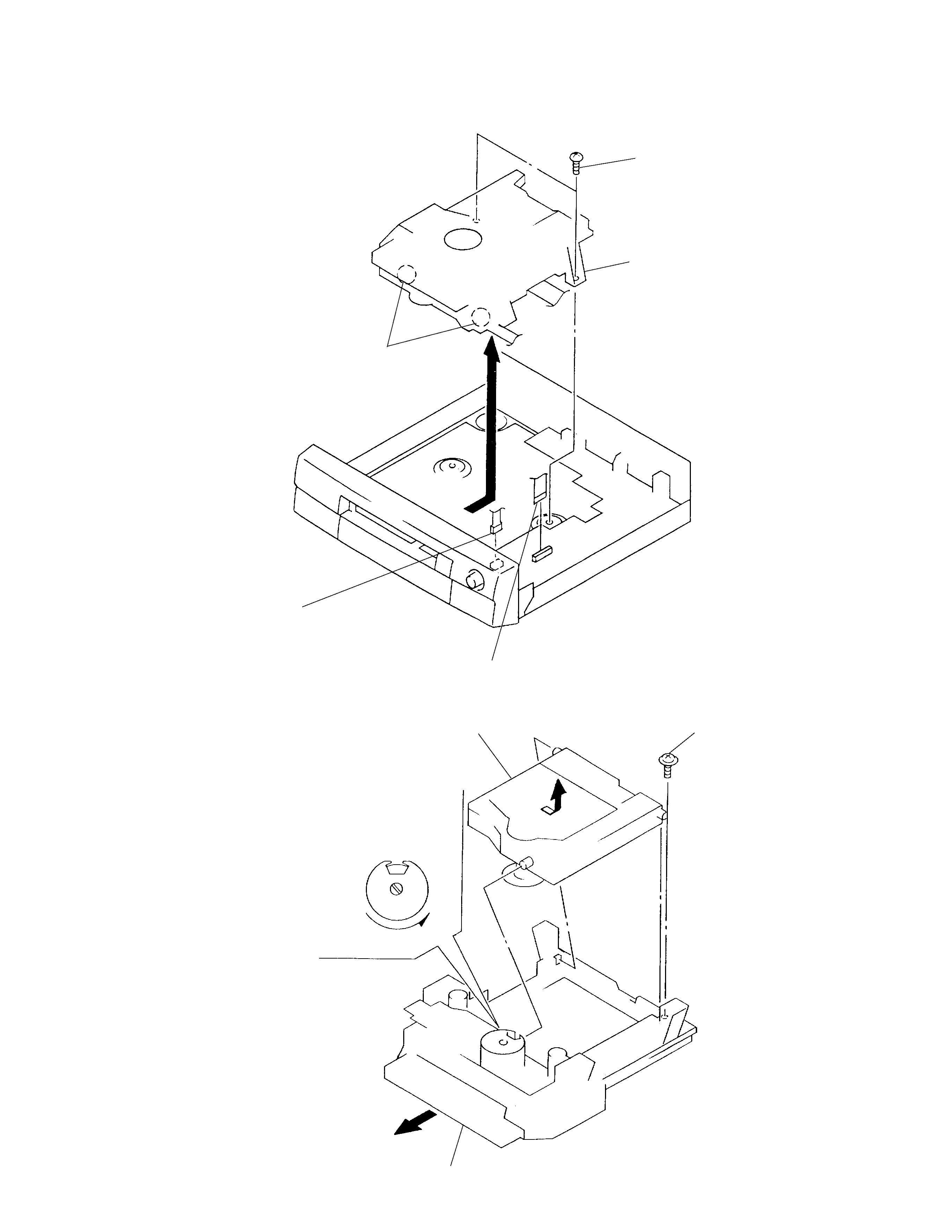
3-1. LOADING PANEL
1Turn the cam in the
direction of arrow.
bottom of chassis
2 Pull out the disc table.
4 Remove the loading panel
in the direction of arrow.
3 claws
bottom of chassis
This section is extracted from
instruction manual.
5
3-2. MD BLOCK
3-3. HOLDER (BU) ASSY
3 BVTP 3
×8
5 MD block
(CDM28-5BD19)
4 claws
1 CN202
2 CN201
1Turn the cam in the direction of arrow.
2 Pull out disc table.
3 yoke bracket
4 holder (BU) assy
(BU-5BD19)