MICROFILM
SERVICE MANUAL
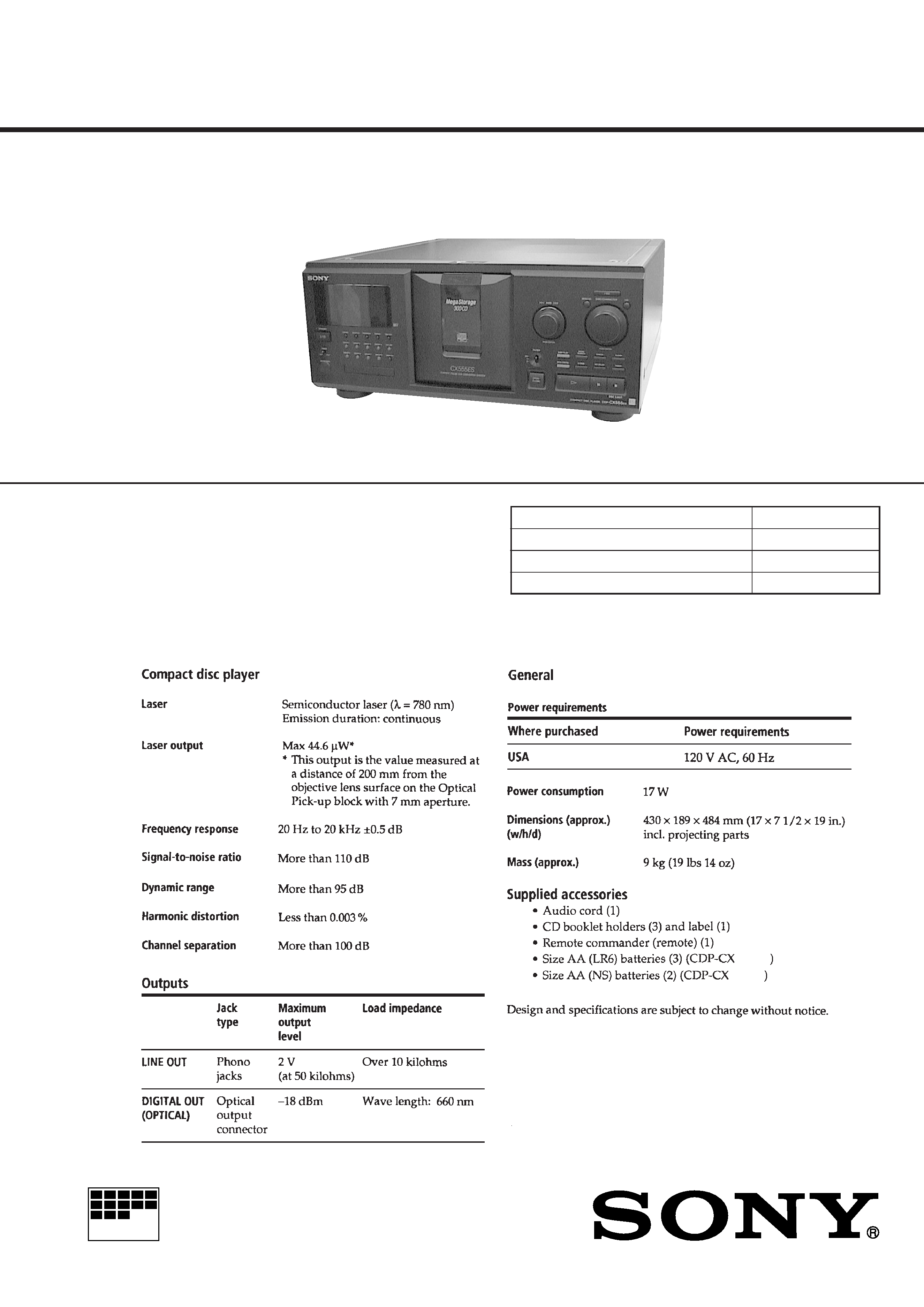
COMPACT DISC PLAYER
US Model
Canadian Model
Model Name Using Similar Mechanism
CDP-CX300
CD Mechanism Type
CDM54-KIBD35B
Base Unit Type
KSM-213BFN/C2NP
Optical Pick-up Type
KSS-213B/C2N
SPECIFICATIONS
CDP-CX333ES/CX555ES
Photo: CX555ES
333ES
555ES
2
TABLE OF CONTENTS
1.
SERVICING NOTES ............................................... 2
2.
GENERAL ................................................................... 8
3.
DISASSEMBLY ......................................................... 9
4.
SERVICE MODE ...................................................... 12
5.
TEST MODE .............................................................. 16
6.
MECHANICAL ADJUSTMENTS ....................... 17
7.
ELECTRICAL ADJUSTMENT ............................ 19
8.
DIAGRAMS
8-1. Block Diagram BD Section ..................................... 21
8-2. Block Diagram MAIN Section ................................ 22
8-3. Note for Printed Wiring Boards
and Schematic Diagrams ................................................ 23
8-4. Printed Wiring Board BD Board ............................. 24
8-5. Schematic Diagram BD Board ................................ 25
8-6. Printed Wiring Board MAIN Board ........................ 26
8-7. Schematic Diagram MAIN Board (1/3) .................. 28
8-8. Schematic Diagram MAIN Board (2/3) .................. 29
8-9. Schematic Diagram MAIN Board (3/3) .................. 30
8-10. Printed Wiring Board JACK Board ......................... 31
8-11. Schematic Diagram JACK Board ............................ 31
8-12. Printed Wiring Board DISPLAY Board .................. 32
8-13. Schematic Diagram DISPLAY Board ..................... 33
8-14. Printed Wiring Board JOG Board ........................... 34
8-15. Schematic Diagram JOG Board .............................. 35
8-16. Printed Wiring Boards D.SENSOR (IN)/
D.SENSOR (OUT)/SENSOR (T) Boards ................... 36
8-17. Schematic Diagram D.SENSOR (IN)/
D.SENSOR (OUT)/SENSOR (T) Boards ................... 37
8-18. Printed Wiring Boards D.MOTOR/D.SWITCH/
KEY/LED/L.T.MOTOR/L.SWITCH (A)/
L.SWITCH (B) Boards ................................................ 38
8-19. Schematic Diagram D.MOTOR/D.SWITCH/
KEY/LED/L.T.MOTOR/L.SWITCH (A)/
L.SWITCH (B) Boards ................................................ 39
8-20. Printed Wiring Board POWER Board ..................... 40
8-21. Schematic Diagram POWER Board ........................ 41
8-22. IC Pin Function Description ........................................... 49
9.
EXPLODED VIEWS ................................................ 54
10. ELECTRICAL PARTS LIST ............................... 61
ATTENTION AU COMPOSANT AYANT RAPPORT
À LA SÉCURITÉ!
LES COMPOSANTS IDENTIFIÉS PAR UNE MARQUE
!
SUR LES DIAGRAMMES SCHÉMATIQUES ET LA LISTE
DES PIÈCES SONT CRITIQUES POUR LA SÉCURITÉ
DE FONCTIONNEMENT. NE REMPLACER CES COM-
POSANTS QUE PAR DES PIÈCES SONY DONT LES
NUMÉROS SONT DONNÉS DANS CE MANUEL OU
DANS LES SUPPLÉMENTS PUBLIÉS PAR SONY.
SAFETY-RELATED COMPONENT WARNING!!
COMPONENTS IDENTIFIED BY MARK
! OR DOTTED
LINE WITH MARK
! ON THE SCHEMATIC DIAGRAMS
AND IN THE PARTS LIST ARE CRITICAL TO SAFE
OPERATION. REPLACE THESE COMPONENTS WITH
SONY PARTS WHOSE PART NUMBERS APPEAR AS
SHOWN IN THIS MANUAL OR IN SUPPLEMENTS PUB-
LISHED BY SONY.
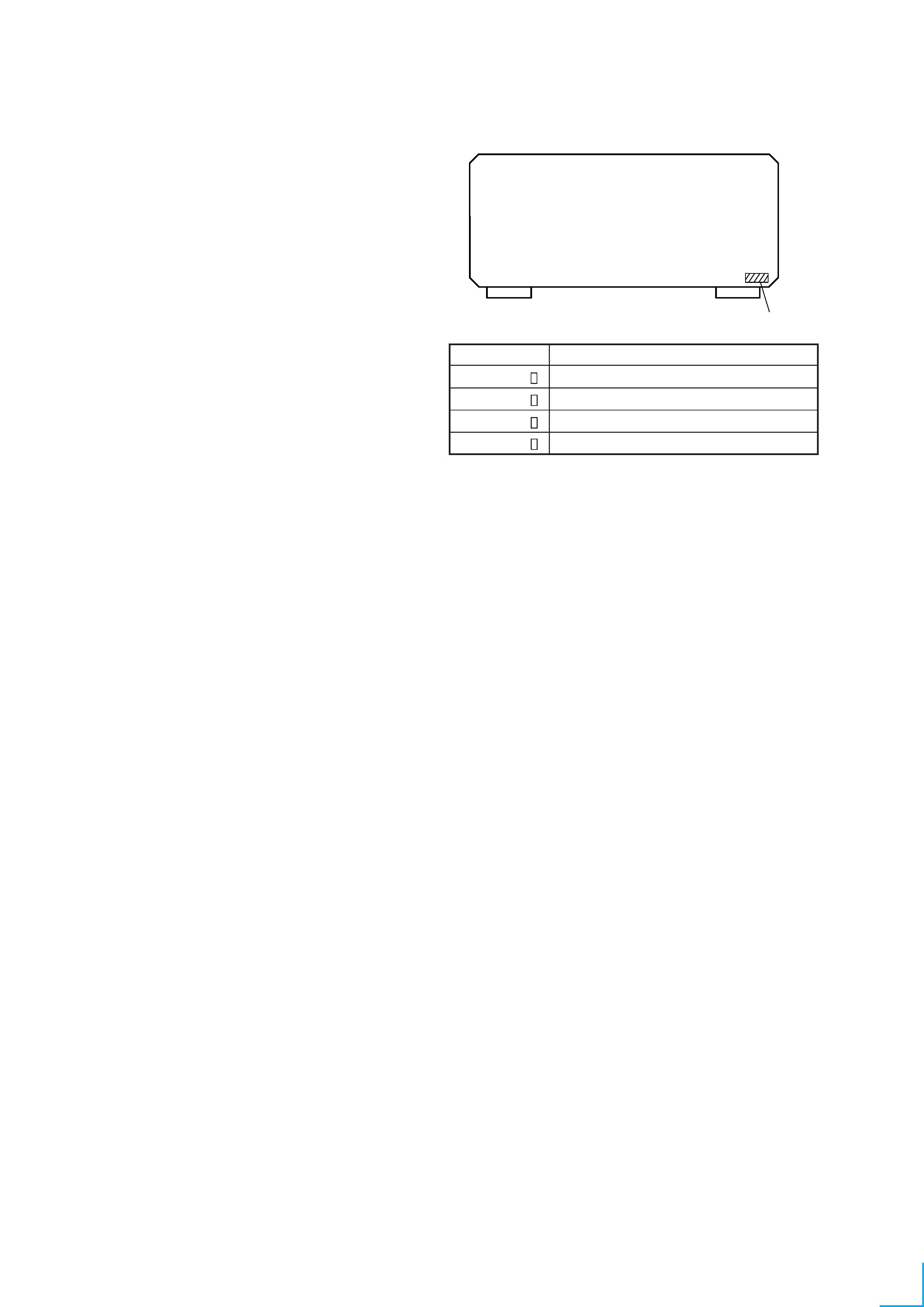
4-217-909-0
4-217-909-1
4-217-909-2
4-217-909-3
CX333ES: US model
CX333ES: Canadian model
CX555ES: US model
CX555ES: Canadian model
PART No.
MODEL
MODEL IDENTIFICATION
-- BACK PANEL --
PART No.
SECTION 1
SERVICING NOTES
3
SAFETY CHECK-OUT
After correcting the original service problem, perform the follow-
ing safety check before releasing the set to the customer:
Check the antenna terminals, metal trim, "metallized" knobs,
screws, and all other exposed metal parts for AC leakage.
Check leakage as described below.
LEAKAGE TEST
The AC leakage from any exposed metal part to earth ground and
from all exposed metal parts to any exposed metal part having a
return to chassis, must not exceed 0.5 mA (500 microamperes).
Leakage current can be measured by any one of three methods.
1. A commercial leakage tester, such as the Simpson 229 or RCA
WT-540A. Follow the manufacturers' instructions to use these
instruments.
2. A battery-operated AC milliammeter. The Data Precision 245
digital multimeter is suitable for this job.
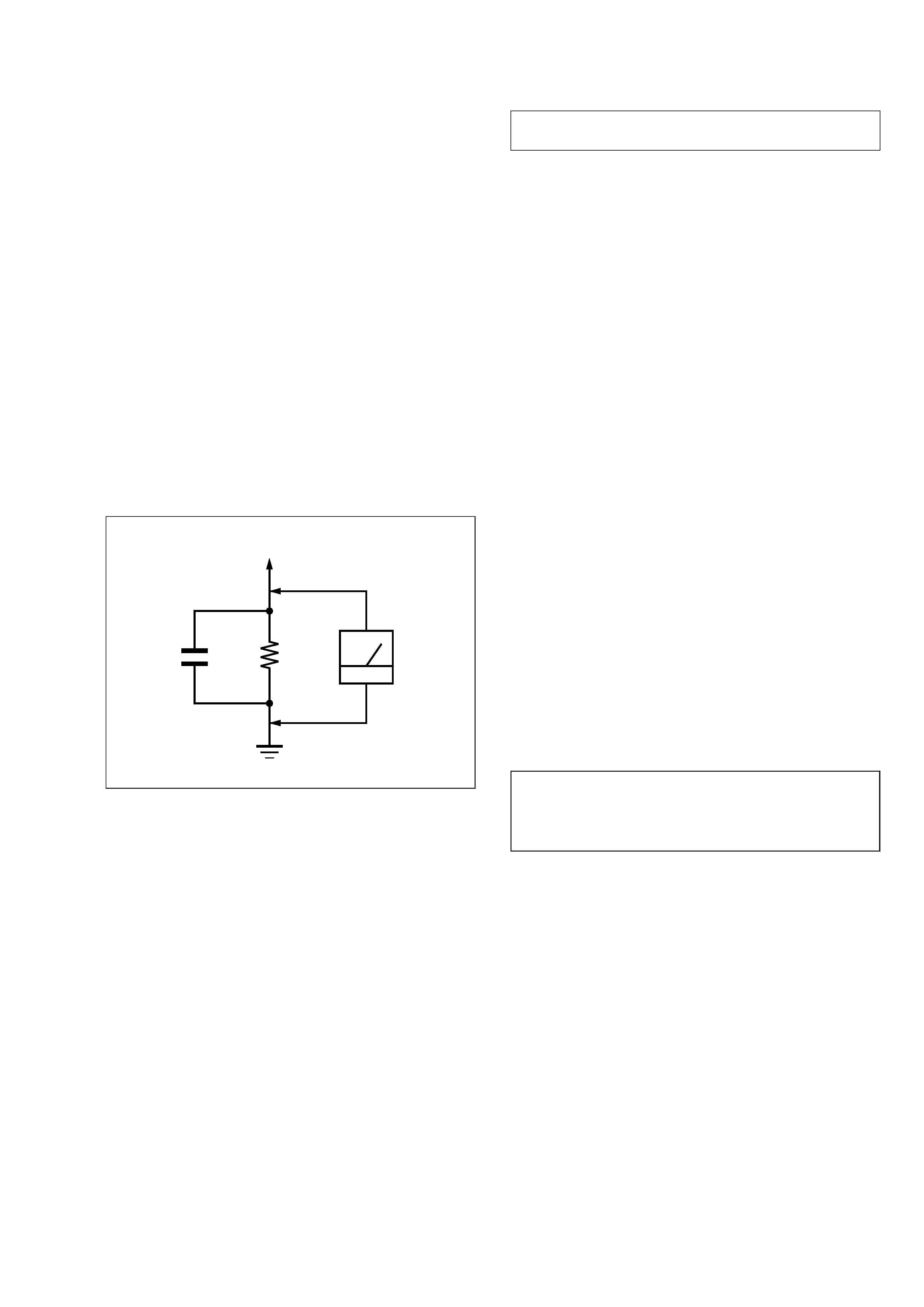
3. Measuring the voltage drop across a resistor by means of a
VOM or battery-operated AC voltmeter. The "limit" indica-
tion is 0.75 V, so analog meters must have an accurate low-
voltage scale. The Simpson 250 and Sanwa SH-63Trd are ex-
amples of a passive VOM that is suitable. Nearly all battery
operated digital multimeters that have a 2 V AC range are suit-
able. (See Fig. A)
Fig. A.
Using an AC voltmeter to check AC leakage.
1.5 k
0.15
µF
AC
voltmeter
(0.75 V)
To Exposed Metal
Parts on Set
Earth Ground
The laser diode in the optical pick-up block may suffer electro-
static break-down because of the potential difference generated
by the charged electrostatic load, etc. on clothing and the human
body.
During repair, pay attention to electrostatic break-down and also
use the procedure in the printed matter which is included in the
repair parts.
The flexible board is easily damaged and should be handled with
care.
NOTES ON LASER DIODE EMISSION CHECK
The laser beam on this model is concentrated so as to be focused
on the disc reflective surface by the objective lens in the optical
pick-up block. Therefore, when checking the laser diode emis-
sion, observe from more than 30 cm away from the objective lens.
LASER DIODE AND FOCUS SEARCH OPERATION
CHECK
Carry out the "S curve check" in "CD section adjustment" and
check that the S curve waveforms is output three times.
Notes on chip component replacement
· Never reuse a disconnected chip component.
· Notice that the minus side of a tantalum capacitor may be dam-
aged by heat.
Flexible Circuit Board Repairing
· Keep the temperature of the soldering iron around 270 °C dur-
ing repairing.
· Do not touch the soldering iron on the same conductor of the
circuit board (within 3 times).
· Be careful not to apply force on the conductor when soldering
or unsoldering.
NOTES ON HANDLING THE OPTICAL PICK-UP
BLOCK OR BASE UNIT
CAUTION
Use of controls or adjustments or performance of procedures
other than those specified herein may result in hazardous ra-
diation exposure.
4
CD-TEXT TEST DISC
This unit is able to display the TEXT data (character information) written in the CD on its fluorescent indicator tube.
The CD-TEXT TEST DISC (TGCS-313:J-2501-126-A) is used for checking the display.
To check, perform the following procedure.
Checking Method:
1. Turn ON the power, set the disc on the disc table with the side labeled as "test disc" as the right side, close the front cover, and chuck
the disc.
2. The following will be displayed on the fluorescent indicator tube. (The display switches each time the [TIME/TEXT] button is pressed.)
Display: CD TEXT TEST DISC (Album Title)
3. Press the [ ] button and play back the disc.
4. The following will be displayed on the fluorescent indicator tube. (If nothing is displayed, press the [TIME/TEXT] button.)
Display: 1 kHz/0 dB/ L&R
5. Rotate [ AMS ] knob to switch the track. The text data of each track will be displayed.
For details of the displayed contents for each track, refer to "Table 1: CD-TEXT TEST DISC Text Data Contents" and "Table 2: CD-
TEXT TEST DISC Recorded Contents and Display".
Restrictions in CD-TEXT Display
In this unit, some special characters will not be displayed properly. These will be displayed as a space or a character resembling it. For
details, refer to "Table 2: CD-TEXT DISC Recorded Contents and Display".
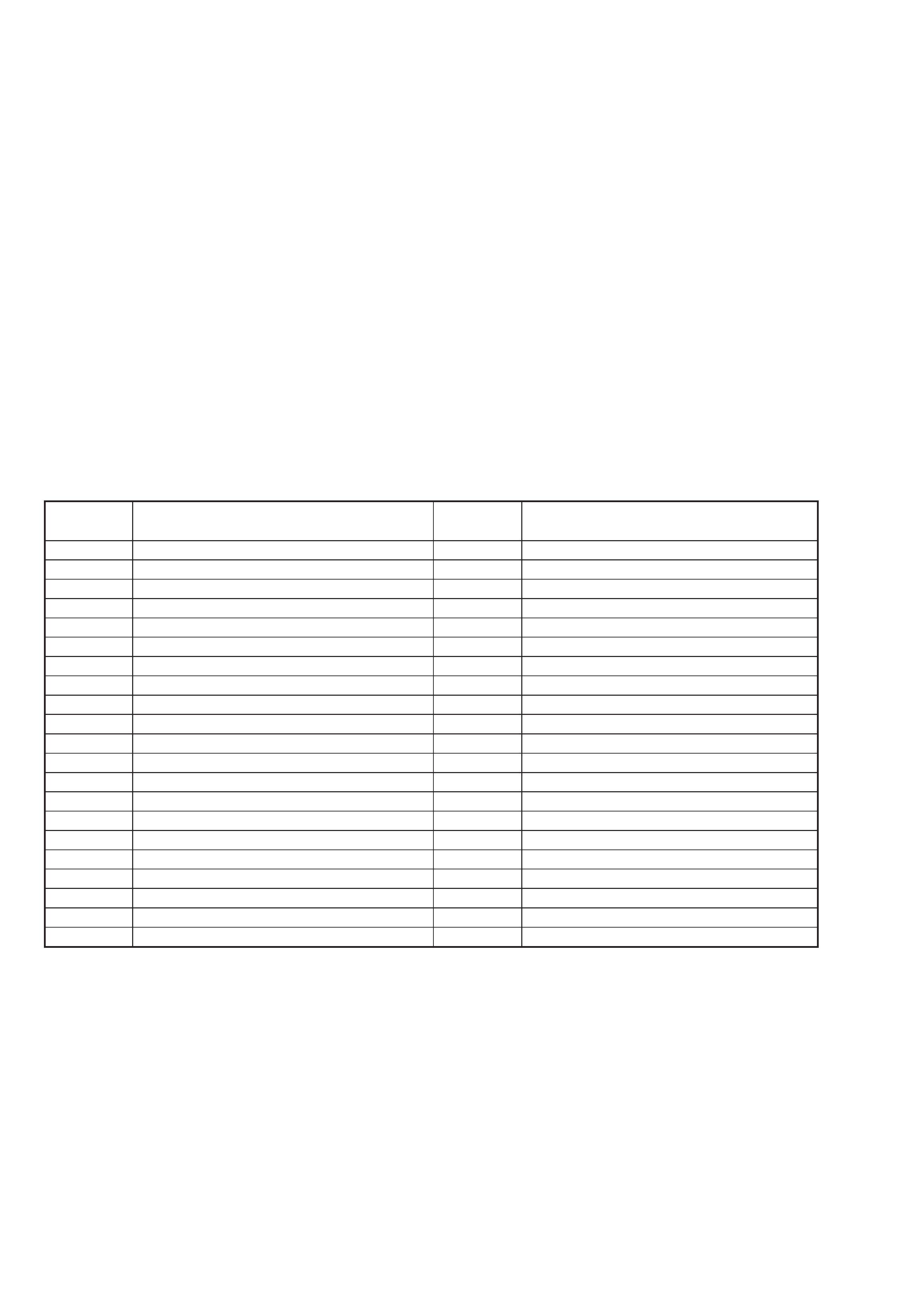
Table 1: CD-TEXT TEST DISC Text Data Contents (TRACKS No. 1 to 41:Normal Characters)
·
±
TRACK
No.
1
2
3
4
5
6
7
8
9
10
11
12
13
14
15
16
17
18
19
20
21
Displayed Contents
1 kHz/0 dB/L&R
20 Hz/0 dB/L&R
40 Hz/0 dB/L&R
100 Hz/0 dB/L&R
200 Hz/0 dB/L&R
500 Hz/0 dB/L&R
1 kHz/0 dB/L&R
5 kHz/0 dB/L&R
7 kHz/0 dB/L&R
10 kHz/0 dB/L&R
16 kHz/0 dB/L&R
18 kHz/0 dB/L&R
20 kHz/0 dB/L&R
1 kHz/0 dB/L&R
1 kHz/-1 dB/L&R
1 kHz/-3 dB/L&R
1 kHz/-6 dB/L&R
1 kHz/-10 dB/L&R
1 kHz/-20 dB/L&R
1 kHz/-60 dB/L&R
1 kHz/-80 dB/L&R
TRACK
No.
22
23
24
25
26
27
28
29
30
31
32
33
34
35
36
37
38
39
40
41
Displayed Contents
1 kHz/-90 dB/L&R
Infinity Zero w/o emphasis//L&R
Infinity Zero with emphasis//L&R
400 Hz+7 kHz(4:1)/0 dB/L&R
400 Hz+7 kHz(4:1)/-10 dB/L&R
19 kHz+20 kHz(1:1)/0 dB/L&R
19 kHz+20 kHz(1:1)/-10 dB/L&R
100 Hz/0 dB/L*
1 kHz/0 dB/L*
10 kHz/0 dB/L*
20 kHz/0 dB/L*
100 Hz/0 dB/R*
1 kHz/0 dB/R*
10 kHz/0 dB/R*
20 kHz/0 dB/R*
100 Hz Squer Wave//L&R
1 kHz Squer Wave//L&R
1 kHz w/emphasis/-0.37 dB/L&R
5 kHz w/emphasis/-4.53 dB/L&R
16 kHz w/emphasis/-9.04 dB/L&R
Note: The contents of Track No. 1 to 41 are the same as those of the current TEST DISC-their titles are displayed.
5
TRACK
No.
42
43
44
45
46
47
48
49
50
51
52
53
54
55
56
57
58
59
60
61
62
63
64
65
66
67
to
99
Recorded Contents
! " # $ % & ´
(21h to 27h) 1kHz 0dB L&R
( ) * + , . / (28h to 2Fh)
012 3456 7 (30h to 37h)
8 9 : ; < = > ? (38h to 3Fh)
@ A B C D E F G (40h to 47h)
H I J K L M N O (48h to 4Fh)
P Q R S T U V W (50h to 57h)
X Y Z [ ¥ ] ^ _ (58h to 5Fh)
a b c d e f g (60h to 67h)
h i j k l m n o (68h to 6Fh)
p q r s t u v w (70h to 77h)
x y z { I } ~
(78h to 7Fh)
i ¢ £ ¤ ¥
§ (A0h to A7h) 8859-1
C ª
¬ PR (A8h to AFh)
·± 23
µ ¶ · (B0h to B7h)
1 º
¿ (B8h to BFh)
ÀÁ ÂÃÄÅ Æ Ç (C0h to C7h)
È É Ê Ë Ì Í Î Ï
(C8h to CFh)
D Ñ Ò ÓÔÕÖ
(D0h to D7h)
Ø ÙÚÛÜ Y
ß (D8h to DFh)
à á â ã ä å æ ç
(E0h to E7h)
è é ê ë ì í î ï
(E8h to FFh)
ñò óôõö ÷ (F0h to F7h)
øù ú û ü y
ÿ
(F8h to FFh)
No.66
No.67
to
No.99
11
3
42
4
Displayed Contents
N All the same
N All the same
N All the same
N All the same
N All the same
N All the same
N All the same
X Y Z [ \ ] ^ _
(58····
N All the same
N All the same
N All the same
x y z { I } ~
(78····
i ¢ £ ¤ ¥
§
(A0····
is not displayed
(A8···· C ª
¬ PR are not displayed
µ · (B0···· · ± 23 ¶ are not displayed
¿ (B8····
1
º
are not displayed
N All the same
N All the same
N All the same
Ù Ú Û Ü Y
ß (D8····
N All the same
N All the same
o ñ òóôõ ö
÷ (F0····
N All the same
N All the same
N All the same
to
N All the same
113
424
Table 2: CD-TEXT TEST DISC Recorded Contents and Display
(In this unit, some special characters cannot be displayed. This is no a fault.)