
-- 1 --
TABLE OF CONTENTS
6. CDM-47
6-1. GENERAL
...................................................................... 6-1
6-2. Tools and Measuring Instruments ...................................... 6-3
6-2-1. General and Special Tools List .............................. 6-3
6-2-1-1.
General Tools ................................................ 6-3
6-2-1-2.
Special Tools ................................................. 6-3
6-2-1-3.
Test Disc ....................................................... 6-3
6-2-1-4.
Measuring Equipments ................................. 6-3
6-2-1-5.
Software ........................................................ 6-3
6-2-1-6.
Expendable and Chemical Supplies ............. 6-3
6-2-2. Setting Single-Operation of CDM-47
Mechanism Block .................................................. 6-4
6-2-3. System Configration .............................................. 6-6
6-2-3-1.
Set up PS/VP System .................................... 6-6
6-2-3-2.
System Configuration ................................... 6-6
6-3. Trouble Shooting ................................................................ 6-8
6-3-1. Before Trouble Shooting ....................................... 6-8
6-3-2. Flowchart for Trouble Shooting ............................ 6-8
6-3-3. Procedure of ATP Test ........................................... 6-9
6-3-3-1.
Pre-setting ..................................................... 6-9
6-3-3-2.
Test Procedure ............................................ 6-10
6-3-4. Drive Function Check .......................................... 6-12
6-3-4-1.
Pre-Setting for Test Mode Operation .......... 6-12
6-3-4-2.
Flowchart .................................................... 6-13
6-3-4-3.
Test Command List ..................................... 6-16
6-3-4-4.
Spindle Motor ............................................. 6-16
6-3-4-5.
Sled Gear Train ........................................... 6-16
6-3-4-6.
2-Axis Actuator .......................................... 6-16
6-3-4-7.
Focusing (Focus Bias) ................................ 6-16
6-3-4-8.
Laser Power ................................................ 6-16
6-3-4-9.
Chucking Mechanism ................................. 6-17
6-3-4-10. Sled Motor .................................................. 6-17
6-3-4-11. Spindle Motor Drive ................................... 6-17
6-3-4-12. E-F Balance ................................................ 6-18
6-3-4-13. RF Level ..................................................... 6-18
6-3-5. Down Load Program ........................................... 6-20
7. DIAGRAMS
7-1. Circuit Boards Location .................................................... 7-1
7-2. IC Pin Function ................................................................. 7-2
7-3. Block Diagrams .............................................................. 7-21
7-4. Frame Schematic Diagram .............................................. 7-29
7-5. Printed Wiring Board/Schematic Diagram ..................... 7-33
Main Section ................................................................... 7-33
Power Supply Section ..................................................... 7-40
Carrier, Mail Box Section ............................................... 7-46
Panel Section ................................................................... 7-52
CD-ROM Drive Section .................................................. 7-55
7-6. IC Block Diagrams ......................................................... 7-67
7-6-1. Main Section ...................................................... 7-67
7-6-2. Power Supply Section ........................................ 7-69
7-6-3. CD-ROM Drive Section ..................................... 7-70
8. EXPLODED VIEWS
8-1.
Case Section ................................................................... 8-1
8-2.
Front Panel Assy Section ................................................ 8-2
8-3.
Chassis Section ............................................................... 8-3
8-4.
Back Panel Section ......................................................... 8-4
8-5.
Carrier Assy Section 1 .................................................... 8-5
8-6.
Carrier Assy Section 2 .................................................... 8-6
8-7.
Carrier Assy Section 3 .................................................... 8-7
8-8.
Disc Case Assy Section .................................................. 8-8
8-9.
Mail Box Assy Section ................................................... 8-9
8-10. CDM-47 Section ........................................................... 8-10
8-11. BU Holder Section ....................................................... 8-11
9. ELECTRICAL PARTS LIST
CDL1100
SERVICE MANUAL
For Technical Service
6-1
SECTION 6
CDM-47
4. After connection to the MA Mounted Board, to open the LD short
land, remove the soldering quickly with a soldering iron whose
insulation resistance is larger than 10M
.
Base Unit Ass'y
1M
1M
1 Wrist-Strap for grounding
2 Conductive sheet or copper plate
LD Short Land
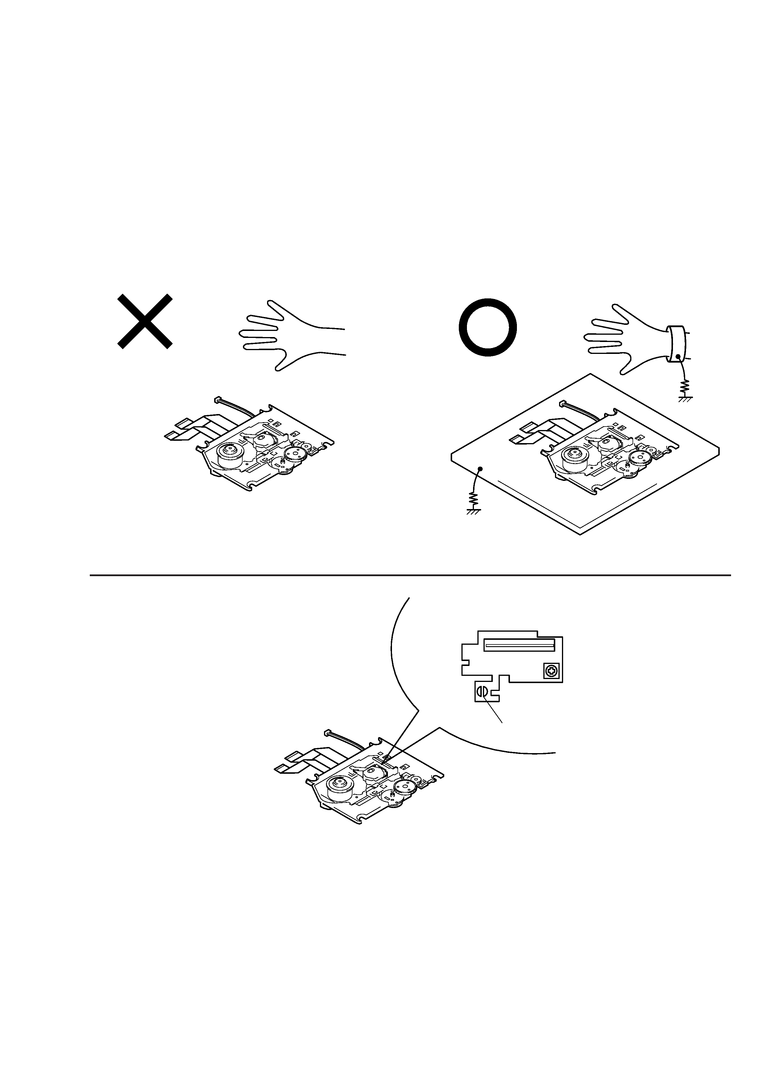
6-1. GENERAL
Note:Note on repairing the Base Unit Ass'y.
When operating or repairing the unit, grounding is required to pre-
vent damage caused by static electricity and is as follows:
1. Grounding for the human body
Besure to wear a wrist-strap for grounding (with impedance lower
than 108
) whose other end is ground. The strap works to drain
away the static electricity build-up on the human body.
2. Grounding for the work table
Be sure to lay a conductive sheet (with impedance lower than 108
)
on the table, sure as a sheet of copper, which is ground.
3. As static electricity build-up on clothes does not drain away, be
careful not to let your clothes touch the unit.
6-2
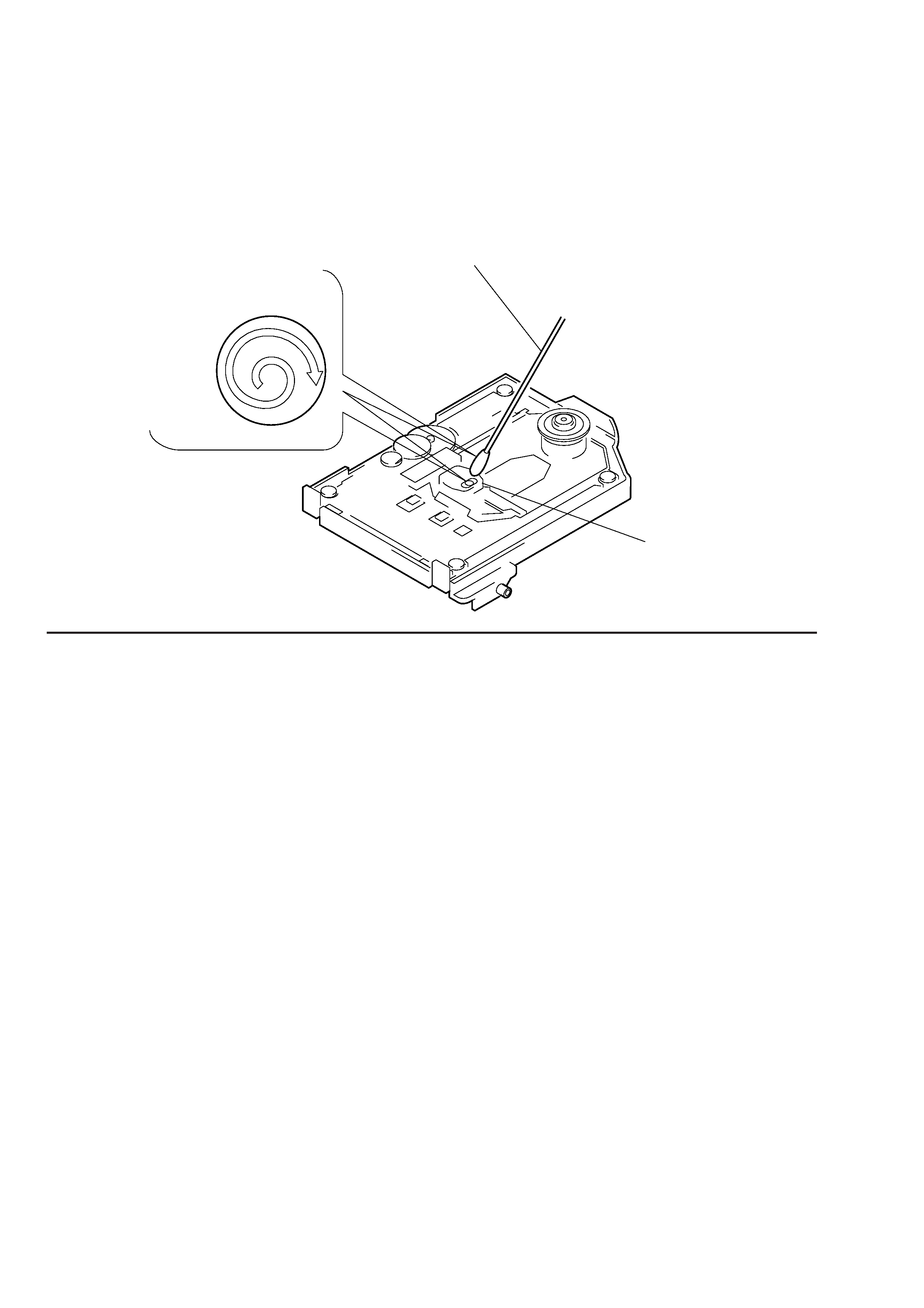
5. Do not apply excessive force to the when wiping. Optical device
is structured by very sensitive mechanism parts.The lens holding
mechanism may have damage if apply excessive force.
Cotton Swab
Optical Pick-up Cover
Wipe the surface of an object lens with
a spiral from the center to outside.
(Refer to Fig A)

6-3
6-2. TOOLS AND MEASURING INSTRUMENTS
6-2-1. GENERAL AND SPECIAL TOOLS LIST
The tools and measuring instruments for performing maintenance on
the CDM-47 series are listed below.
6-2-1-1. General Tools
SONY Parts No.
Driver 2mm
(7-700-749-01)
Driver 2.6mm
(7-700-749-03)
Tweezers
(7-700-753-02)
Round Nose Plier
(7-700-757-01)
Cutter
(7-700-758-02)
Soldering Iron (20W)
Desoldering Metal Braid (Solder Wick)
Multi Meter (DRM)
6-2-1-2. Special Tools
IBM PS/VP System
PS/VP and the monitor (640kbyte RAM, 3.5" FDD, HDD, Video
RAM-CGA or Higher, DOS Ver. 6.2 or later)
Adaptec SCSI board AHA-1520B or AHA-2940
DC Power Supply
(1-413-362-12)
(If no power supply unit is available:Supply power from the
CDL1100 unit.)
Power cord
(1-559-370-11)
SCSI 50P Flat Cable
(J-902-900-0A)
AU-CN Board
(A-8080-815-A)
BLER Counter For TC940X
(J-907-564-0A)
CDL1100 (CDM-47) CONTROLLER
(J-2501-141-A)
Active Speaker
6-2-1-3. Test Disc
SONY Test Disc (YEDS-18)
(3-702-101-01)
SONY Test Disc (TGRS-21)
SONY Test Disc (YEHS-4)
(3-702-548-01)
6-2-1-4. Measuring Equipments
Osilloscope Dual Trace 20MHz (probe x10)
DC Volt Meter (min. 10mA)
6-2-1-5. Software
ATP415 System Disc (OR-D019)
(8-980-308-19)
6-2-1-6. Expendable and Chemical Supplies
Cotton Swab (200 pieces)
(7-740-900-65)
Lens Cleaning Liquid
(J-250-100-0A)
Molykote Grease (EM-30L)
(4-918-645-01)
Hanarl (SFL-9)
(7-400-000-00)
6-4
3. While pressing the TEST button of the controller, turn on the power of the CDL1100 or power supply unit.
4. After about 1 second later, release the TEST button.
5. This sets the test mode. To enter the other mode, refer to the following table, set the dip switch, and press the TEST button.
6-2-2. Setting Single-Operation of CDM-47 Mechanism Block
Jig :
CDL-1100 (CDM-47) controller : J-2501-141-A
Power supply unit
: 1-413-362-12 (If no power supply units available : Supply power from the CDL1100 unit)
CD test disc (YEDS-18)
: 3-702-101-01
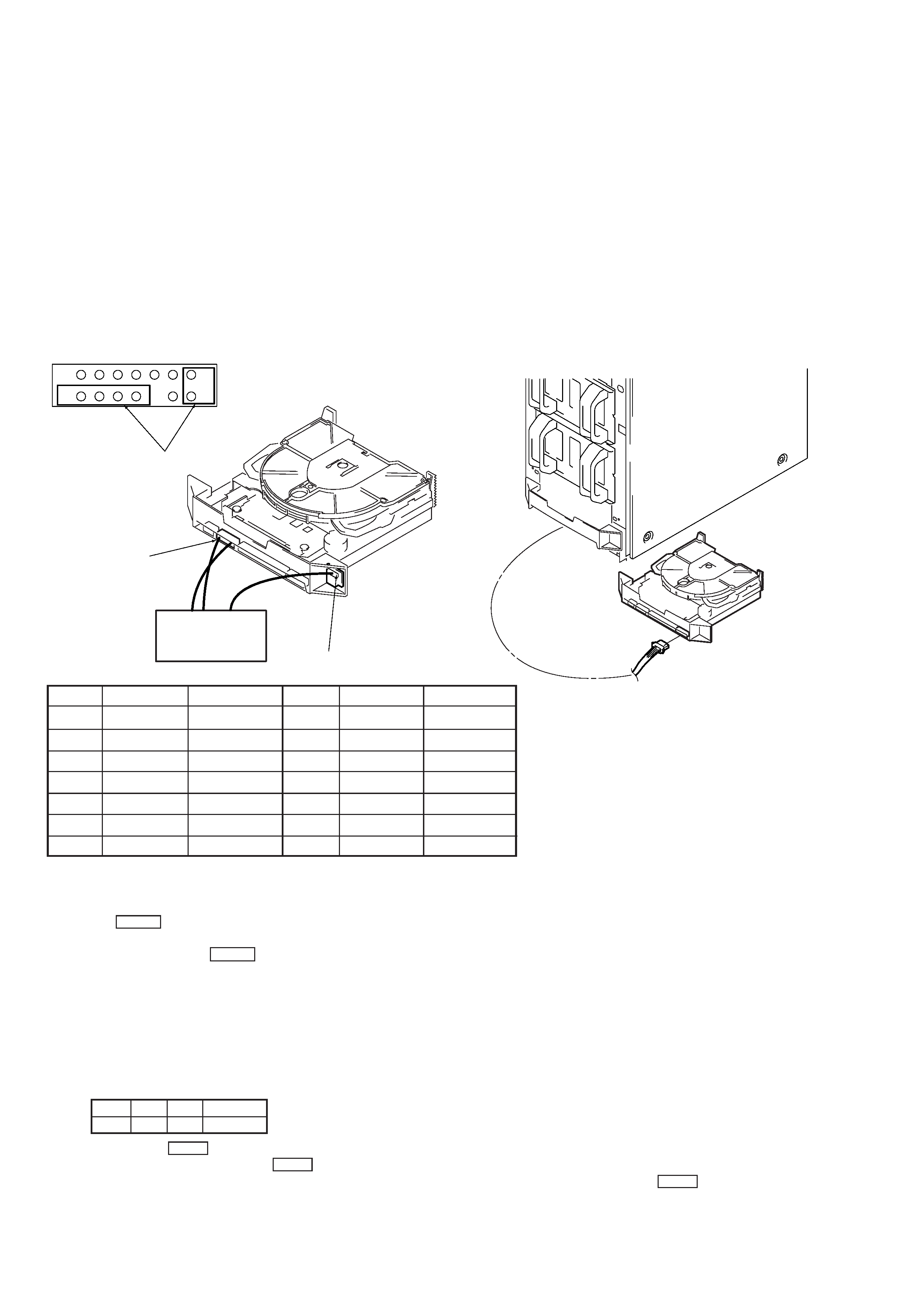
Connection Method :
If no power supply unit is available : Supply power from the CDL1100 unit.
Connect the unit (CNJ202, CN56:MA-22 board) and controller.
CDL1100
CDM-47
Supplying power from the CDL1100 unit
Connect this part to the
controller
CNJ202
(MA-C22 board)
Controller
CN56 (CN board)
CNJ201
CDM-47
CNJ202 enlargement
Pin No.
1
2
3
4
5
6
7
Signal Name
Ground
Ground
Ground
Ground
Ground
Ground
Ground
Jig Wire Color
White
--
--
--
--
--
--
Pin No.
8
9
10
11
12
13
14
Signal Name
Parity
ID0
ID1
ID2
NC
P/A
TEST
Jig Wire Color
Brown
Black
Yellow
Blue
--
--
Red
7
8
1
14
[Disc Chucking/Unchucking Method]
1. Connect the controller.
2. Load a disc directly into the drive with your hand.
3. Press the EJECT button of the controller. The LEDs will go off in the order of red and green.
When both LEDs go off, it means that both discs have been chucked.
4. To eject the disc, press the EJECT button again.
5. The LEDs light up in the order of green and red. When both LEDs light up, it means that the discs have been unchucked.
NOTE :
If the LEDs remain lit or off even when chucking/unchucking is performed, S51 (red:UNCHUCK), S52 (green:CHUCK) of the CDM-47
LDSW board may be improperly connected.
[Single-Operation of CDM-47]
1. Chuck the disc beforehand.
2. Set the COMMAND SW of the controller to the test mode.
ID2
H
ID1
L
ID0
H
PARITY
H