SERVICE MANUAL
Sony Corporation
Audio Group
Published by Sony Engineering Corporation
US Model
CUSTOM INTEGRATED AV SYSTEM
9-877-752-03
2004J16-1
© 2004.10
Ver. 1.2 2004. 10
SPECIFICATIONS
CAV-M1000ES
CAV-M1000ES Main Unit
Audio (each channel)
Continuous average power output (FTC)
All channels:
30 W per channel min. RMS at 8
ohms, any two channels driven
from 20 Hz to 20 kHz with no
more than 0.09 % THD.
40 W per channel min. RMS at 4
ohms, any two channels driven
from 20 Hz to 20 kHz with no
more than 0.7 % THD.
Frequency response: 5 Hz to 70 kHz
± 3dB
Input sensitivity:
160 mV for 1 W output, 650 mV for
full output (30 W) with volume
control set to maximum.
Input impedance:
20 k ohms
Signal-to-noise ratio: 92 dB (A-weighted )
Bass control range:
100 Hz
± 14 dB, 2 dB step
Treble control range: 10 kHz
± 14 dB, 2 dB step
SOURCE 1-8 and ZONE 1-6 AUDIO OUT
Frequency response: 5 Hz to 55 kHz
± 3dB
THD @ 2 V:
0.08 %
Signal-to-noise ratio: 102 dB (A-weighted @ 2 V)
Video
Input/output impedance:
75 ohm
Video insertion loss: 0 dB (50 Hz - 6 MHz)
General
12V trigger:
300 mA max each zone,
total 1.2 A max
Power requirements: 120 V 60 Hz
Power consumption: 540 W
Dimensions:
430
× 175 × 433 mm
(16 7/ 8
× 6 7/ 8 × 17 1/ 16 inches)
(w/h/d)
Mass:
24 kg (52 lbs 15 oz)
RM-TP100 RF Remote Control
Composition
Interface system:
Liquid crystal touch panel
Liquid crystal size:
5.2 inches (320
× 240 dots)
Touch panel:
Resistance sensible system
Analog type
Maximum range from the RF Antenna:
7 m (22 feet 11 1/ 2 inches)
(The maximum range differs
depending on the environment
where you use the RF Remote
Control.)
Power supply: Rechargeable (Ni-MH) battery
Maximum external dimensions:
227
× 146 × 45 mm
(9
× 5 3/ 4 × 1 7/ 8 inches)
(w/h/d, including projecting
parts and controls)
Mass:
0.8 kg (1 lbs 13 oz)
(Main unit only, including the
rechargeable battery)
Operating temperature:
5
°C to 35 °C (41°F to 95°F)
Design and specifications are subject
to change without notice.
· CAV-M1000ES Main Unit
· RM-TP100 RF Remote Control
· RMB-TP100 Charger cradle for
the RF Remote Control
· Ferrite core
· AN-M1000 RF Antenna
· AC power cord
· Plug-in 4-terminal screw-type
connector for speaker (6)
· Installation Manual
2
CAV-M1000ES
Flexible Circuit Board Repairing
· Keep the temperature of the soldering iron around 270 °C
during repairing.
· Do not touch the soldering iron on the same conductor of the
circuit board (within 3 times).
· Be careful not to apply force on the conductor when soldering
or unsoldering.
Notes on chip component replacement
· Never reuse a disconnected chip component.
· Notice that the minus side of a tantalum capacitor may be
damaged by heat.
SAFETY-RELATED COMPONENT WARNING!!
COMPONENTS IDENTIFIED BY MARK 0 OR DOTTED LINE
WITH MARK 0 ON THE SCHEMATIC DIAGRAMS AND IN
THE PARTS LIST ARE CRITICAL TO SAFE OPERATION.
REPLACE THESE COMPONENTS WITH SONY PARTS WHOSE
PART NUMBERS APPEAR AS SHOWN IN THIS MANUAL OR
IN SUPPLEMENTS PUBLISHED BY SONY.
UNLEADED SOLDER
Boards requiring use of unleaded solder are printed with the lead-
free mark (LF) indicating the solder contains no lead.
(Caution: Some printed circuit boards may not come printed with
the lead free mark due to their particular size)
: LEAD FREE MARK
Unleaded solder has the following characteristics.
· Unleaded solder melts at a temperature about 40 °C higher
than ordinary solder.
Ordinary soldering irons can be used but the iron tip has to be
applied to the solder joint for a slightly longer time.
Soldering irons using a temperature regulator should be set to
about 350
°C.
Caution: The printed pattern (copper foil) may peel away if
the heated tip is applied for too long, so be careful!
· Strong viscosity
Unleaded solder is more viscou-s (sticky, less prone to flow)
than ordinary solder so use caution not to let solder bridges
occur such as on IC pins, etc.
· Usable with ordinary solder
It is best to use only unleaded solder but unleaded solder may
also be added to ordinary solder.
SAFETY CHECK-OUT
After correcting the original service problem, perform the following
safety check before releasing the set to the customer:
Check the antenna terminals, metal trim, "metallized" knobs, screws,
and all other exposed metal parts for AC leakage.
Check leakage as described below.
LEAKAGE TEST
The AC leakage from any exposed metal part to earth ground and
from all exposed metal parts to any exposed metal part having a
return to chassis, must not exceed 0.5 mA (500 microamperes.).
Leakage current can be measured by any one of three methods.
1. A commercial leakage tester, such as the Simpson 229 or RCA
WT-540A. Follow the manufacturers' instructions to use these
instruments.
2. A battery-operated AC milliammeter. The Data Precision 245
digital multimeter is suitable for this job.
3. Measuring the voltage drop across a resistor by means of a
VOM or battery-operated AC voltmeter. The "limit" indication
is 0.75 V, so analog meters must have an accurate low-voltage
scale. The Simpson 250 and Sanwa SH-63Trd are examples
of a passive VOM that is suitable. Nearly all battery operated
digital multimeters that have a 2 V AC range are suitable. (See
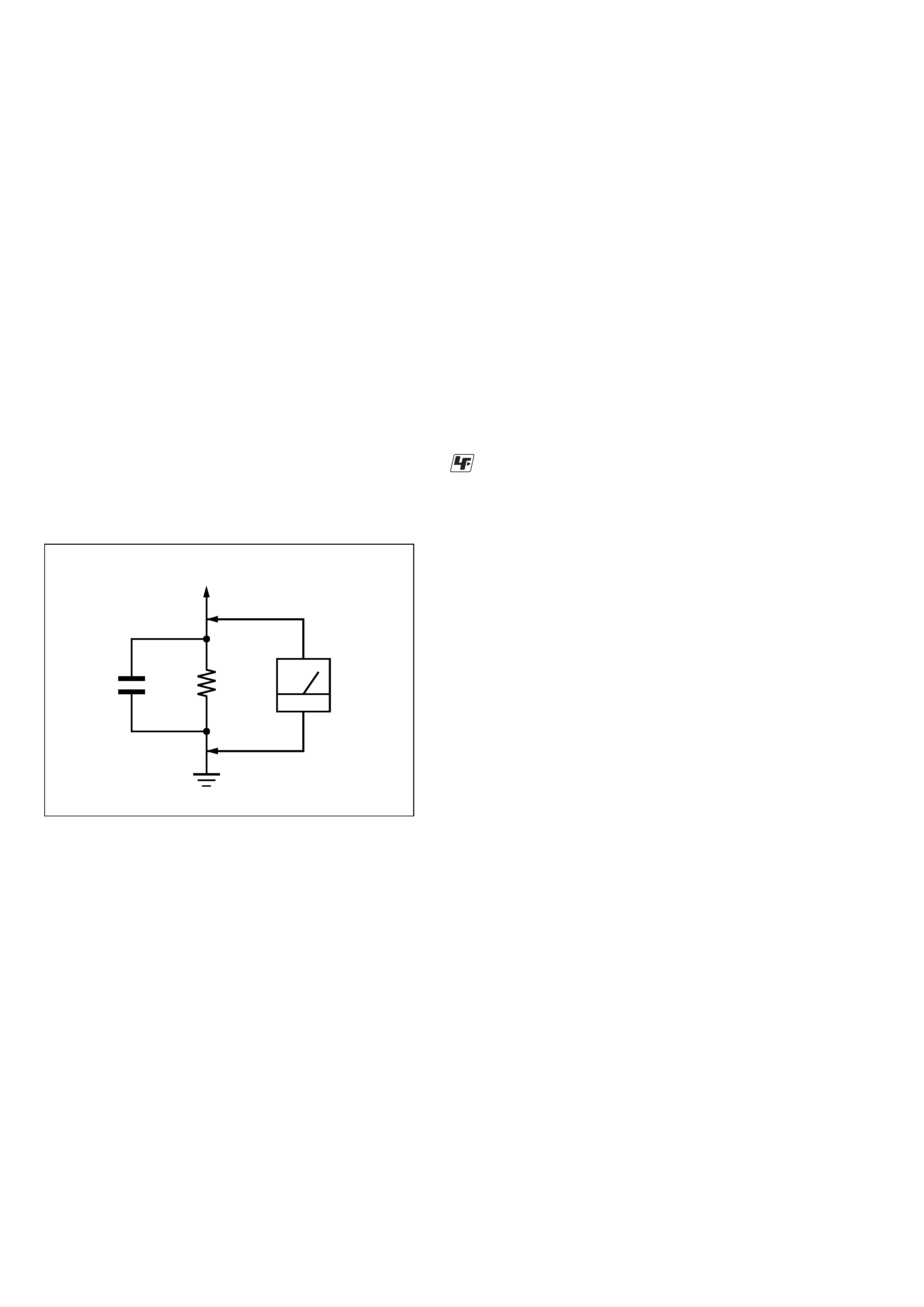
Fig. A)
Fig. A.
Using an AC voltmeter to check AC leakage.
1.5 k
0.15
µF
AC
voltmeter
(0.75 V)
To Exposed Metal
Parts on Set
Earth Ground

3
CAV-M1000ES
TABLE OF CONTENTS
1.
SERVICING NOTE ................................................... 4
2.
GENERAL ................................................................... 8
3.
DIAGRAMS
3-1.
Block Diagram MAIN/POWER Section .................. 14
3-2.
Block Diagram AUDIO I/O Section ......................... 15
3-3.
Block Diagram VIDEO I/O Section ......................... 16
3-4.
Block Diagram
AMP/SPEAKER/PRE OUT Section ......................... 17
3-5.
Block Diagram
IR OUT/RS232C/12V TRIGGER Section ................ 18
3-6.
Block Diagram
RF REMOTE/RF ANTENNA Section ...................... 19
3-7.
Printed Wiring Board AMP Section ......................... 20
3-8.
Schematic Diagram AMP Section ............................ 21
3-9.
Printed Wiring Board
AMP BASE Section (SIDE A) .................................. 22
3-10. Printed Wiring Board
AMP BASE Section (SIDE B) .................................. 23
3-11. Schematic Diagram AMP BASE Section ................. 24
3-12. Printed Wiring Board AUDIO I/O BRD Section ...... 25
3-13. Schematic Diagram
AUDIO I/O BRD Section (1/4) ................................. 26
3-14. Schematic Diagram
AUDIO I/O BRD Section (2/4) ................................. 27
3-15. Schematic Diagram
AUDIO I/O BRD Section (3/4) ................................. 28
3-16. Schematic Diagram
AUDIO I/O BRD Section (4/4) ................................. 29
3-17. Printed Wiring Board VIDEO I/O BRD Section ....... 30
3-18. Schematic Diagram
VIDEO I/O BRD Section (1/2) ................................. 31
3-19. Schematic Diagram
VIDEO I/O BRD Section (2/2) ................................. 32
3-20. Printed Wiring Board
DISPLAY Section (SIDE A) ..................................... 33
3-21. Printed Wiring Board
DISPLAY Section (SIDE B) ..................................... 34
3-22. Schematic Diagram DISPLAY Section (1/3) ............ 35
3-23. Schematic Diagram DISPLAY Section (2/3) ............ 36
3-24. Schematic Diagram DISPLAY Section (3/3) ............ 37
3-25. Printed Wiring Board FRONT PANEL Section ....... 38
3-26. Schematic Diagram FRONT PANEL Section .......... 39
3-27. Printed Wiring Board SPEAKER OUT Section ....... 40
3-28. Schematic Diagram SPEAKER OUT Section ......... 41
3-29. Printed Wiring Board RJ45 Section ......................... 42
3-30. Schematic Diagram RJ45 Section ............................ 43
3-31. Printed Wiring Board PRE OUT BRD Section ........ 44
3-32. Schematic Diagram PRE OUT BRD Section ........... 45
3-33. Printed Wiring Board
RS232C/12V TRIGGER Section .............................. 46
3-34. Schematic Diagram
RS232C/12V TRIGGER Section .............................. 47
3-35. Printed Wiring Board IR OUT Section .................... 48
3-36. Schematic Diagram
IR OUT/CONNECTOR Section ............................... 49
3-37. Printed Wiring Board CONNECTOR Section ......... 50
3-38. Printed Wiring Board REGULATOR Section .......... 51
3-39. Schematic Diagram REGULATOR Section ............. 52
3-40. Printed Wiring Board AC INLET Section ................ 53
3-41. Schematic Diagram AC INLET Section ................... 54
3-42. Printed Wiring Board
RF ANTENNA Section (AN-M1000) ....................... 55
3-43. Schematic Diagram
RF ANTENNA Section (AN-M1000) ....................... 55
3-44. Printed Wiring Board
RF REMOTE CONTROL Section (RM-TP100) ...... 56
3-45. Schematic Diagram
RF REMOTE CONTROL Section (RM-TP100) ...... 57
3-46. Printed Wiring Board
PA UNIT Section (SIDE A) ...................................... 58
3-47. Printed Wiring Board
PA UNIT Section (SIDE B) ...................................... 59
3-48. Schematic Diagram PA UNIT Section (1/2) ............ 60
3-49. Schematic Diagram PA UNIT Section (2/2) ............ 61
4.
EXPLODED VIEWS
4-1.
Overall Section ................................................................ 70
4-2.
Front Panel Section ......................................................... 71
4-3.
Chassis Section ................................................................ 72
4-4.
Back Panel Section .......................................................... 73
4-5.
RF Remote Control (RM-TP100) Section ....................... 74
4-6.
Charger Cradle (RMB-TP100) Section ........................... 75
4-7.
RF Antenna (AN-M1000) Section .................................. 76
5.
ELECTRICAL PARTS LIST .................................. 77
4
CAV-M1000ES
SECTION 1
SERVICING NOTE
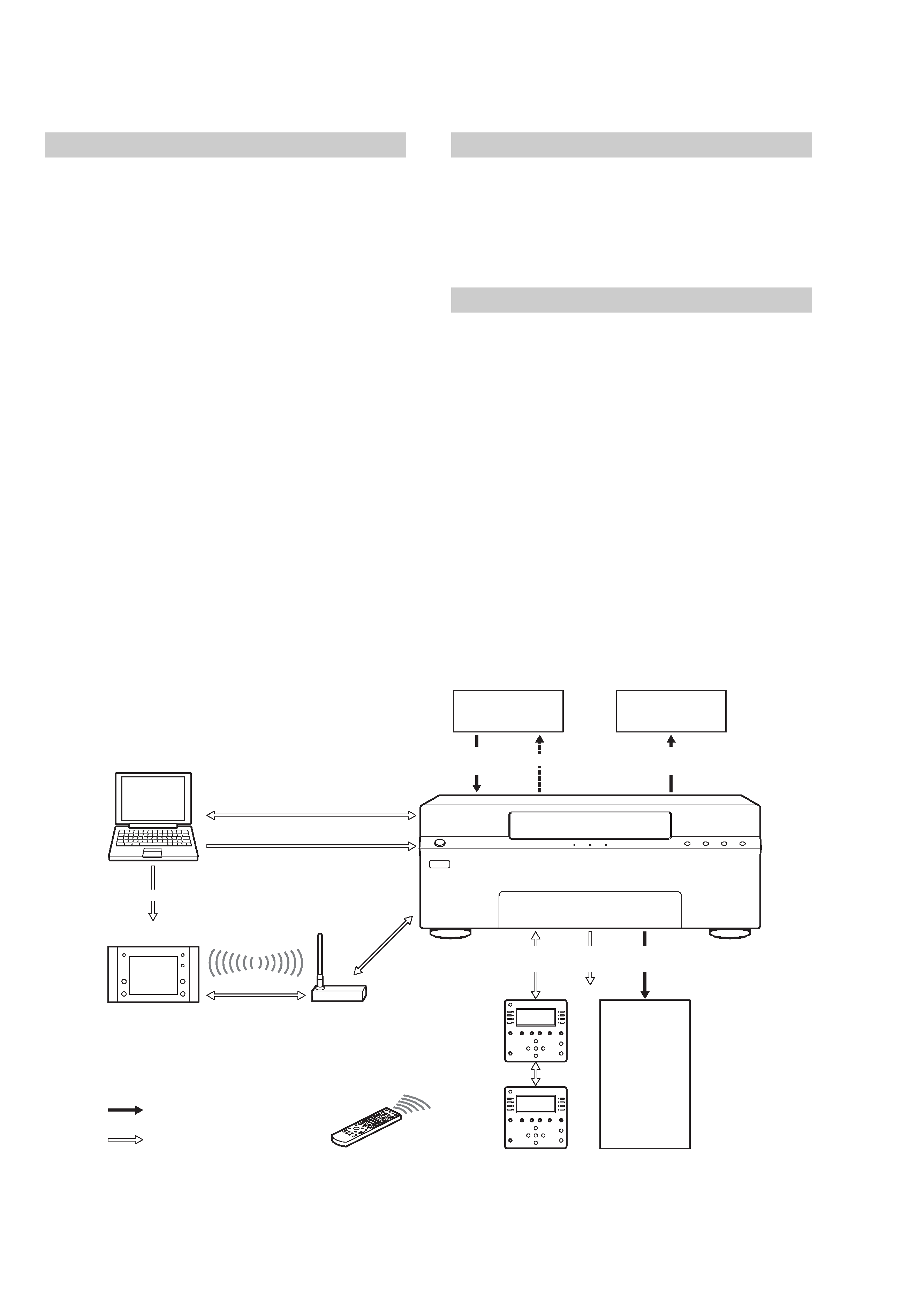
Main Unit
· Zones: Up to six zones receive up to eight source
audio/video signals.
Preamp Outs: Four fixed outputs for zones 1 to 4,
and two variable outputs for zones 5 and 6.
Amplification: All six zones have built-in stereo
audio amplifiers at 30 Watts per channel.
Video outputs for all six zones.
Keypad connections: RJ45 connectors for all six zones
using CAT5 cables.
· Sources: Up to eight audio/video sources can be
selected by all six zones.
· Remote code entry: Remote code commands can be
learned by the Main Unit.
on your computer
on the Main Unit
· 12 V trigger: Six zone-specific 12 V status outputs; each
300 mA max, total 1.2 A.
· RS232C port (Front): Allows you to connect the Main
Unit to your computer to update the settings or
firmware.
· RS232C ports (Rear): Allow you to connect a Sony DVD
Mega Changer (ex. DVP-CX777ES) and a Sony A/V
Receiver (ex. STR-DA5000ES) to the Main Unit.
Keypad
· LCD contrast adjustment.
· Connecting IR IN to an IR emitter enables you to use
the IR Remote Control for the additional range.
· RJ45 connectors enable you to use two Keypads in a
single zone.
RF Remote Control
· LCD panel configurable through your computer.
· Controls the audio/video sources in the main zone and
the other zones.
· Customize touch panels via an RS232C cross cable
connected to your computer.
Audio/Video
Source 1 ~ 8
Each input of the
A/V Receiver
Audio/Video
Signal
Serial
RJ45
Zone
Status
Audio/Video
Signal
Zone 1 6
IR
Zone 1 6
Display/Signal
Main
Keypad
Subsidiary
Keypad
IR Remote Control
for the Keypad
Computer
RS232C
Preset Commands
RF Antenna
Preset Commands
: Signal
: Command
RF Remote Control
Audio/Video
Signal
5
CAV-M1000ES
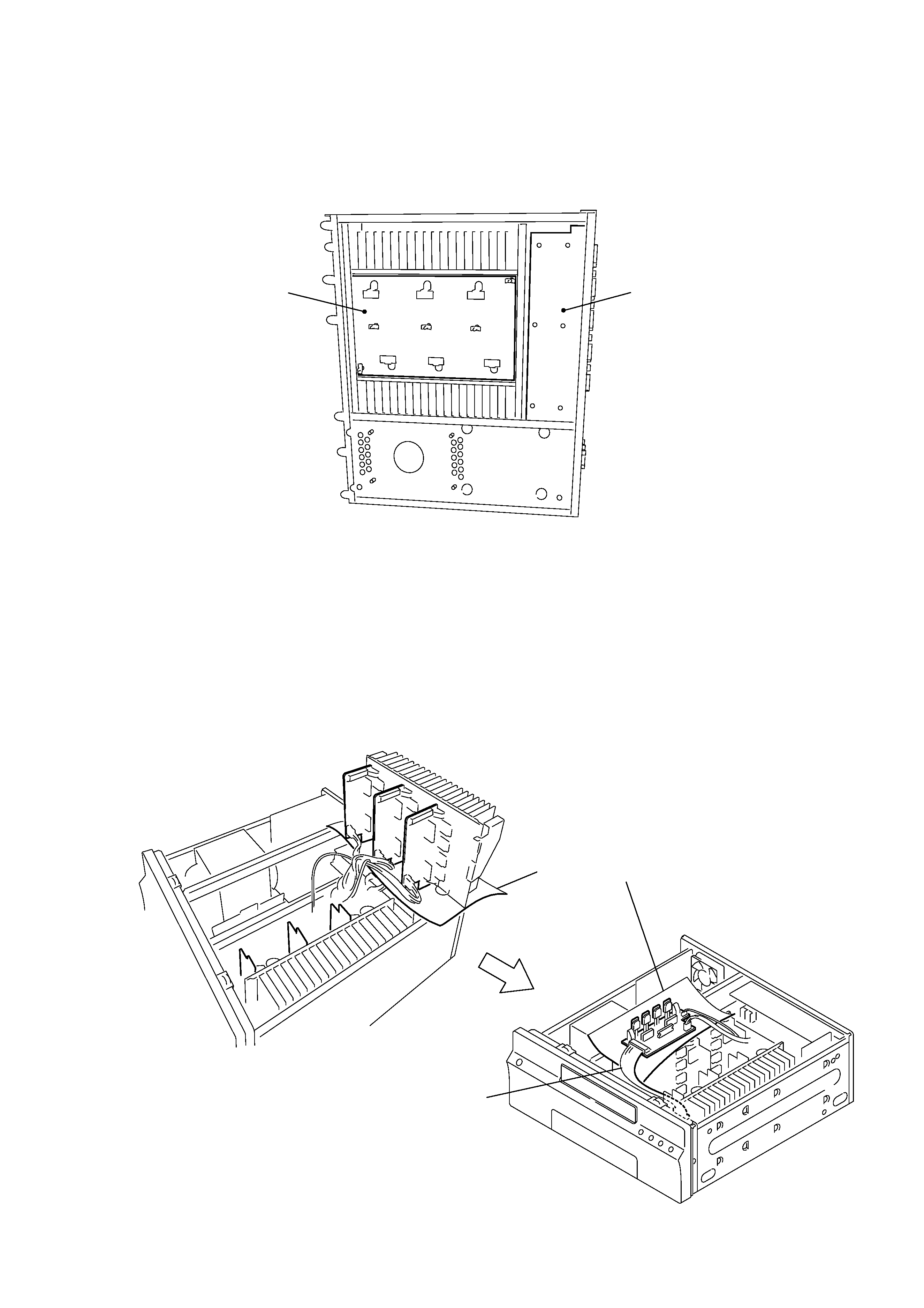
· SERVICE POSITION OF AMP BASE BOARD AND SPEAKER BOARD
· SERVICE POSITION OF AMP BOARD
AMP BASE board
SPEAKER board
The AMP BASE board and the SPEAKER board can be checked after the bottom panel is removed from the unit.
2
3
1
4
5
6
Insulated sheet should be used.
The six pieces of the AMP board are used as shown from No. 1 to 6 check only the defective AMP board by
inserting the extension cable.
Extension cable
(J-2501-269-A)(15P)