INSTRUCTION FOR USE
EM 203

CONTENTS
1
TECHNICAL OVERVIEW
1.1
Computer Control
1.2
Diversity
1.3
HIDYN plus® noise reduction system
1.4
Block diagrams
2
POSSIBLE TRANSMITTER/RECEIVER COMBINATIONS
2.1
EM 203 receiver/SK 2012 TV(HiDyn plus®) and SKM 4031 HiDyn plus®
2.2
EM 203 receiver/SK 50/250 UHF and SKM 5000 (HiDyn plus®)
2.3
EM 203 receiver/SER 20 transceivers
3
PUTTING THE EM 203 TO WORK
3.1
Mains connection
3.2
Antenna connection
3.3
AF connection
3.4
Start-up procedure/operating indicators
4
AVAILABLE MODULES
4.1
EM 1046 RX RECEIVER MODULE
4.1.1
Adjustment
4.1.2
Receiver frequencies
4.1.3
Squelch
4.1.4
Selection RF signal/deviation/battery condition
4.1.5
Display-text/frequency/battery condition
4.1.6
Entry of brief text
4.1.7
System configurations and specifications
4.1.8
Remote monitoring of transmitter battery
4.1.9
Monitoring of audio signals
4.1.10
Stand-by
4.2
MONITOR
4.2.1
LED indicators
4.2.2
Monitor headphones
5
TECHNICAL DATA

Introduction
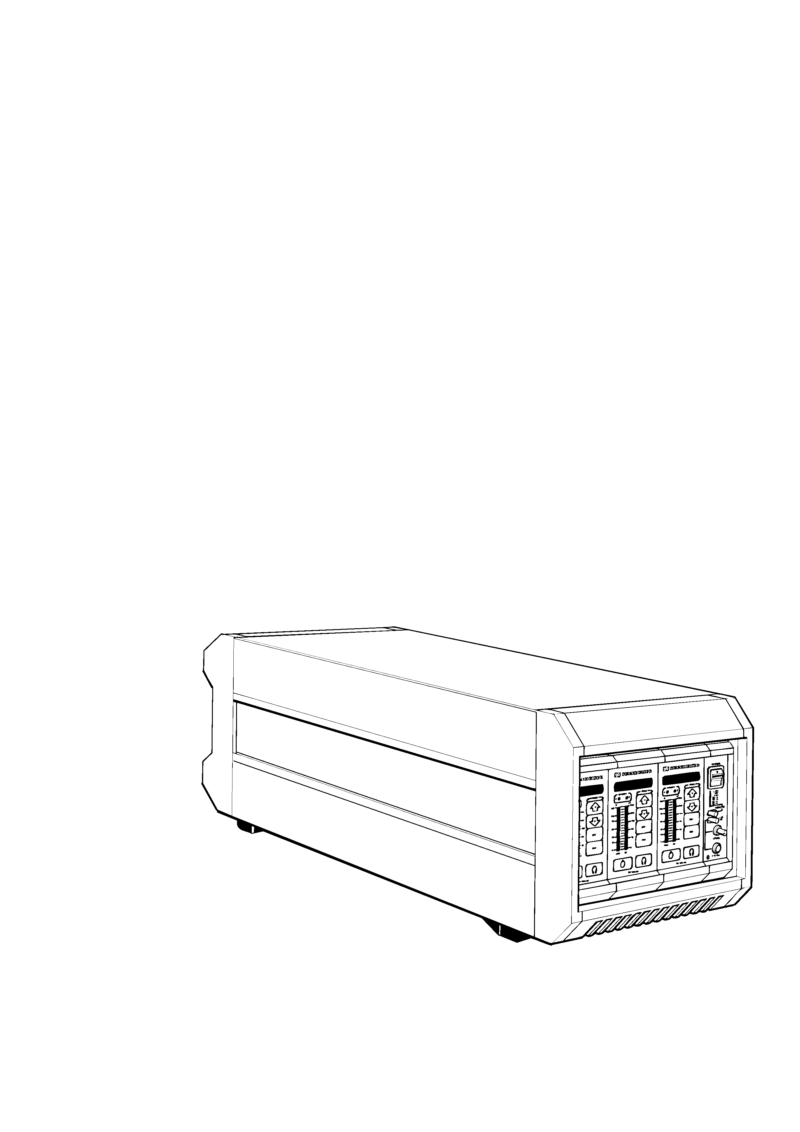
The wireless Mikroport multi-channel sound transmission system EM
1046 is a transmitter/receiver system in a modular design. It offers
comfortable handling and can be relied on for dependable service.
·
3-channel diversity receiver EM 203 with microprocessor-controlled
receiver modules
·
Ultimate flexibility in the selection of transmitter and receiver
frequencies thanks to easy-to-replace PROMs and EEPROMs.
The present manual shall help you to get acquainted with the EM 203
receiver.
·
The chapter "START-UP PROCEDURE" helps you to connect the
unit to the mains and to put it to work.
·
The chapter "AVAILABLE MODULES" provides you with
information on every single module. It explains how to adjust them
to satisfy your individual transmission requirements.
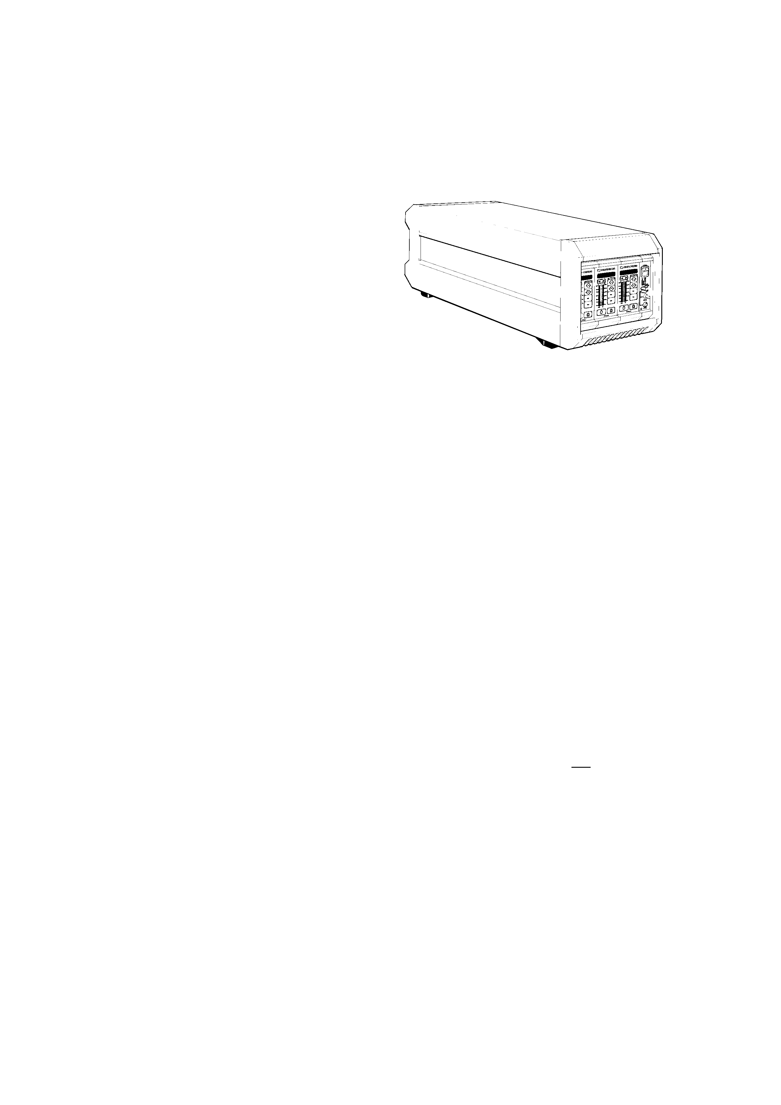
The necessary modules for this receiver system are incorporated into a
"Mainframe". For programming and servicing, the EM 1046 RX
receiver modules can be removed to the front. Output module, input
module and mains power supply module, however, are integral parts of
the system.
IMPORTANT INFORMATION
Each HF input is supplied with a wideband power distributor 1:3,
which intendedly does not affect the adjustment possibilities of the
EM 1046 RX receiver modules. In order to achieve sufficient sensitivity
and protection against subscriber's extention stations, an antenna with
booster and pre-selection is required. In general, Sennheiser's
AB 1036 TV antenna booster is used.
Refer programming of the EEPROMs in the receiver modules to
qualified service personnel or Sennheiser's Service Department,
30900 Wedemark, Germany.

Technical overview
1
Computer control
1.1
Diversity
1.2
HiDyn plus® noise reduction
1.3
Block diagrams
1.4
Every single EM 1046 RX receiver module has an in-built micro-
processor for the RF section, the operating elements and all indicators.
It serves to control the following components or parameters:
·
phase locked loop (PLL) synthesizer
·
function of keys
·
8 digit LED display
·
two LED bargraph displays
·
true diversity
·
monitoring
·
squelch threshold
·
description fields
·
stand-by
·
storage of all receiver parameters (e. g. receiver frequencies) in a
permanent memory
During diversity operations, the microprocessor controls every one of the
two receiver chains that are combined on one module.
The receiver parameters and the selectable frequencies can easily be
changed with the help of a conventional computer system as every
receiver module incorporates an additional service interface. Changes
are only possible within the admissible RF bandwidth.
The software can easily be adapted to your individual requirements and
updated at any time by Sennheiser's Service Department. Our
servicemen simply replace the PROM in the receiver modules.
Computer control
1.1