Scanning system : CCIR standard (625 TV lines, 25 frames/sec.)
Interlace : PLL 2:1 interlace
Image device : 1/2 inch solid state image device CCD
Picture elements : 795 (Horizontal) x 596 (Vertical)
Effective picture elements : 752 (Horizontal) x 582 (Vertical)
Synchronizing system : Line lock/External sync (automatic switching)
Resolution : 560 TV lines horizontally, 350 TV lines vertically
Video output level : 1.0 Vp-p/75
W , composite
Video S/N ratio : More than 50 dB
Minimum required illumination : Approx. 0.02 lux with a F 1.2 lens,
(incandescent lighting)
Approx. 0.03 lux with a F 1.4 lens
Backlight compensation : Manual ON/OFF switching, zone light measuring system
(Active when using an auto-iris lens)
Electronic iris function : Manual ON/OFF switching
Electronic iris range : 0.02 lux to 10,000 lux (F1.2, lens)
0.03 lux to 15,000 lux (F1.4, lens)
Flange-back : 12.5 mm
± 0.8 mm
Gamma correction :
g = 0.45
Lens mount : CS mount (or C mount with the supplied adaptor)
Environmental conditions : Temperature: -10
°C ~ + 50 °C
Humidity: less than 90 % (no condensation)
Power supply : 24 V AC, (
±4 V) 50 Hz
Power consumption : 3.1 W (with auto iris lens)
2.4 W (without auto iris lens)
Weight : Approx. 330 g (without lens)
SERVICE MANUAL
B/W CCD Camera
VCB-3574IRP
(Product Code : 117 061 24)
(South East Asia)
(Europe)
FILE NO.
REFERENCE No. SM5310037
L72H4/XE
NOTE : 1. Parts order must contain model number, part number, and description.
2. Substitute parts may be supplied as the service parts.
3. N. S. P. : Not available as service parts.
Design and specification are subject to change without notice.
The components designated by a symbol ( ! ) in this schematic diagram designates components whose value are of
special significance to product safety. Should any component designated by a symbol need to be replaced, use only the
part designated in the Parts List. Do not deviate from the resistance, wattage, and voltage ratings shown.
PRODUCT SAFETY NOTICE
CONTENTS
DISASSEMBLY, ADJUSTMENT, PARTS LIST.....FILE1
CIRCUIT DIAGRAMS
OVERALL WIRING, CA-1 CIRCUIT ...........FILE2
CA-2 CIRCUIT ............................................FILE3
CA-3 CIRCUIT ............................................FILE4
CA-4 CIRCUIT ............................................FILE5
CA-5 CIRCUIT ............................................FILE6
SPECIFICATIONS

Scanning system : CCIR standard (625 TV lines, 25 frames/sec.)
Interlace : PLL 2:1 interlace
Image device : 1/2 inch solid state image device CCD
Picture elements : 795 (Horizontal) x 596 (Vertical)
Effective picture elements : 752 (Horizontal) x 582 (Vertical)
Synchronizing system : Line lock/External sync (automatic switching)
Resolution : 560 TV lines horizontally, 350 TV lines vertically
Video output level : 1.0 Vp-p/75
, composite
Video S/N ratio : More than 50 dB
Minimum required illumination : Approx. 0.02 lux with a F 1.2 lens,
(incandescent lighting)
Approx. 0.03 lux with a F 1.4 lens
Backlight compensation : Manual ON/OFF switching, zone light measuring system
(Active when using an auto-iris lens)
Electronic iris function : Manual ON/OFF switching
Electronic iris range : 0.02 lux to 10,000 lux (F1.2, lens)
0.03 lux to 15,000 lux (F1.4, lens)
Flange-back : 12.5 mm
± 0.8 mm
Gamma correction :
= 0.45
Lens mount : CS mount (or C mount with the supplied adaptor)
Environmental conditions : Temperature: -10
°C ~ + 50 °C
Humidity: less than 90 % (no condensation)
Power supply : 24 V AC, (
±4 V) 50 Hz
Power consumption : 3.1 W (with auto iris lens)
2.4 W (without auto iris lens)
Weight : Approx. 330 g (without lens)
SERVICE MANUAL
B/W CCD Camera
VCB-3574IRP
(Product Code : 117 061 24)
(South East Asia)
(Europe)
FILE NO.
REFERENCE No. SM5310037
L72H4/XE
NOTE : 1. Parts order must contain model number, part number, and description.
2. Substitute parts may be supplied as the service parts.
3. N. S. P. : Not available as service parts.
Design and specification are subject to change without notice.
The components designated by a symbol ( ! ) in this schematic diagram designates components whose value are of
special significance to product safety. Should any component designated by a symbol need to be replaced, use only the
part designated in the Parts List. Do not deviate from the resistance, wattage, and voltage ratings shown.
PRODUCT SAFETY NOTICE
CONTENTS
1. DISASSEMBLY ....................................2
2. BOARD LOCATION ............................. 3
3. ADJUSTMENT .....................................4
4. PARTS LIST .........................................6
SCHEMATIC DIAGRAM
SPECIFICATIONS
-2-
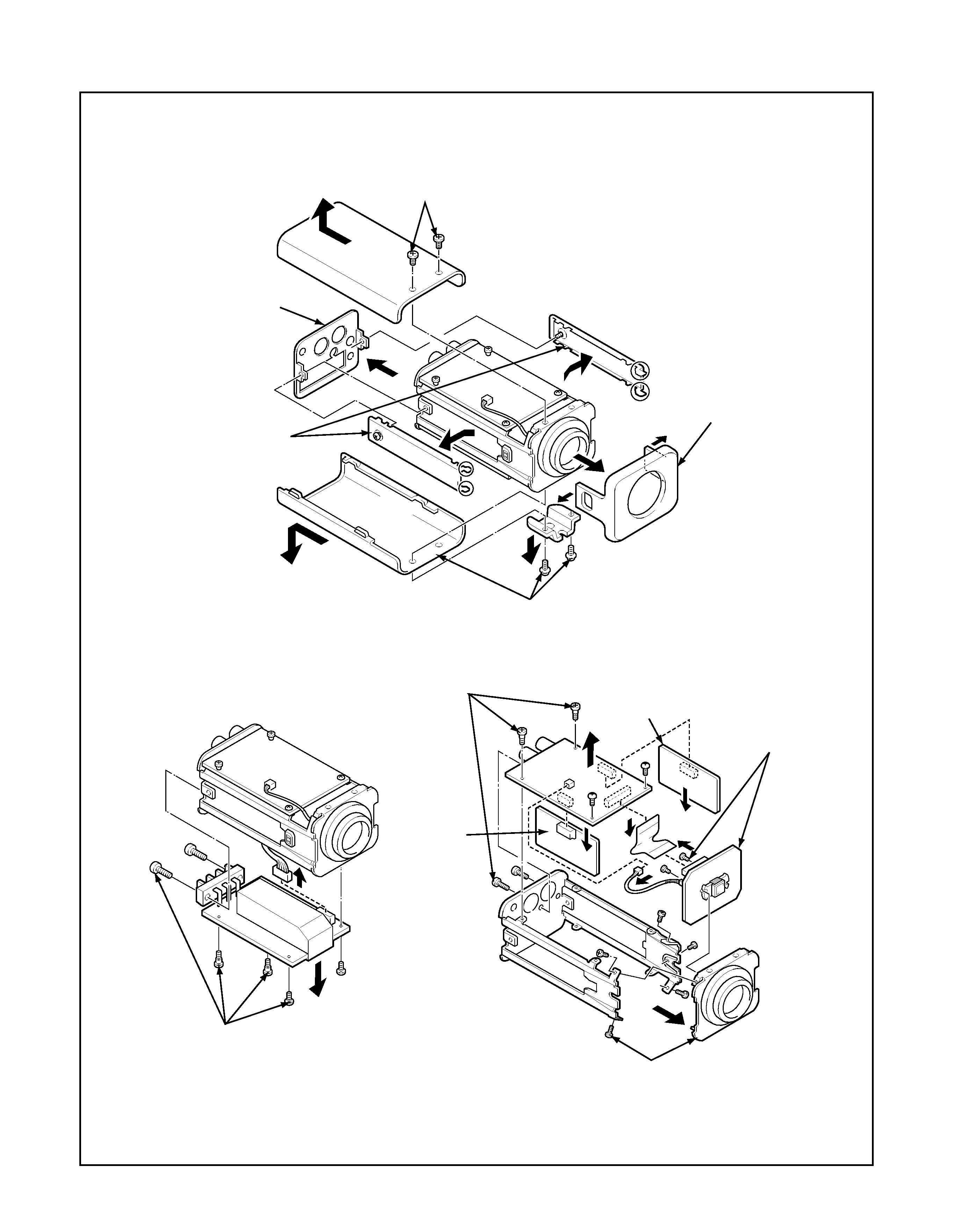
1. DISASSEMBLY
1. Loosen the two screws,
and then remove the left
and right side panels.
2. Remove the rear panel.
3. Remove the two screws,
and then pull out the top cabinet.
4. Remove the two screws, and then remove
the bracket and pull out the bottom cabinet.
5. Remove the front panel.
6. Remove the six screws, and then
disconnect the CA-5 board assembly
connector from the CA-2 board assembly.
7. Remove the six screws, then remove
the CA-2/CA-3/CA-4 board assemblies
and the FPC, and disconnect the connector.
8. Remove the five screws, and then
remove the lens mount bracket.
9. Remove the two
screws, and then
remove the CA-1
board assembly.
CA-4
board
CA-5 board
CA-3 board
CA-2 board
CA-1 board
-3-
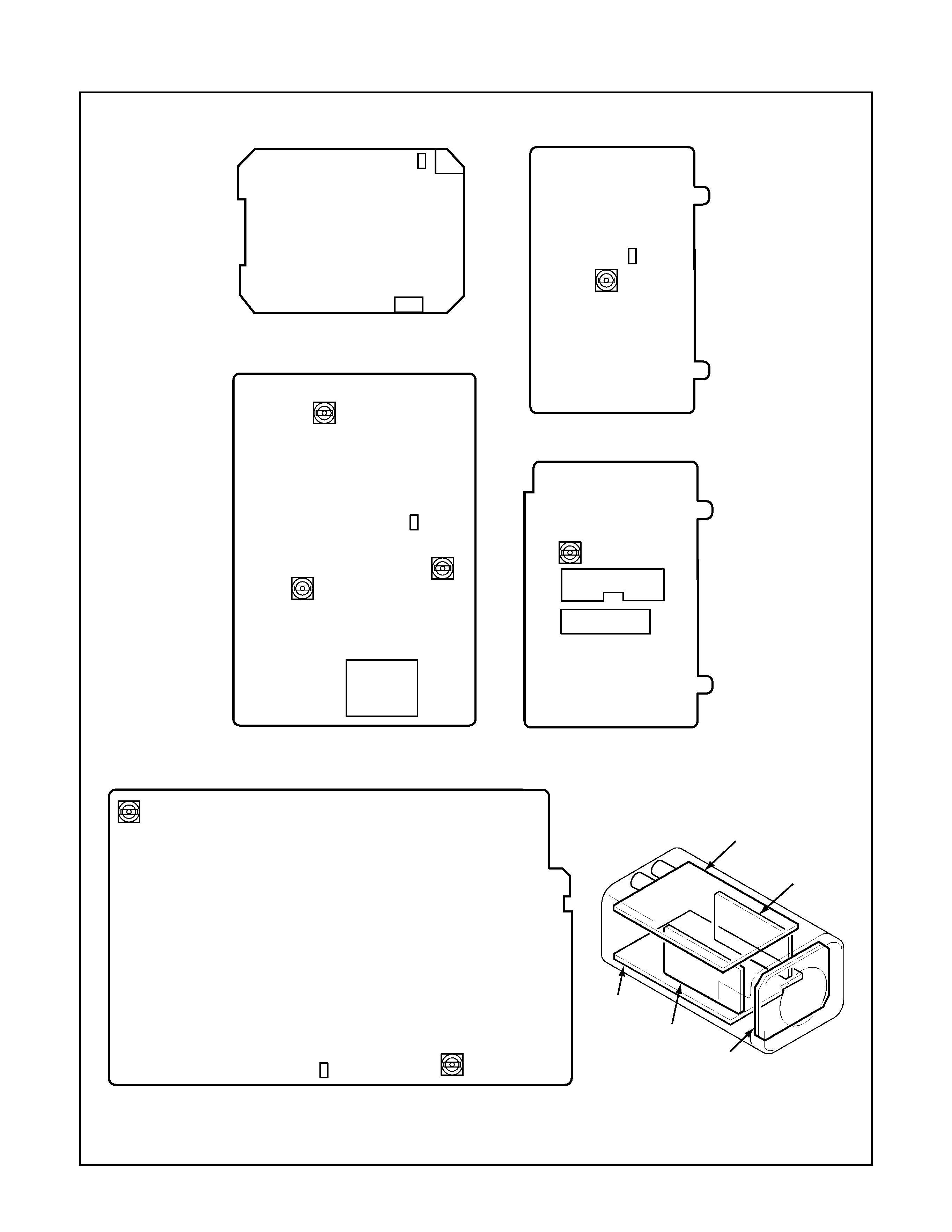
2. BOARD LOCATION
VR501
VR201
TP301
TP201
TP501
SUB
RGL
Abbr.
TP101
CA-1 board (Side A)
CA-3 board (Side A)
CA-4 board (Side A)
CA-2 board (Side B)
TP102
SUB
RGL
Abbr.
TP202
VR204
VR203
CT301
TP502
VR502
VR401
SW402
SW401
CA-5 board (Side A)
SW403
CN206
CA-2 board
CA-3 board
CA-5 board
CA-4 board
CA-1 board
-4-
3. ADJUSTMENT
3-1. ADJUSTMENT PREPARATION
1. Set the ITE gray scale chart II(
=0.45) to the viewer.
2. Set the angle of adjustment control (VR) before starting
adjustment at the center or temporary adjustment (nearly
adjusted) unless specified.
3. Set the trigger signal of oscilloscope to VIDEO OUT, and
apply H sync unless specified.
4. Set the operating condition of the camera (switch settings
inside the side panel) as follows in adjusting unless speci-
fied.
E.l./BLC switch (SW402):"OFF" position
Auto iris switch (SW401):"DC" position
5. The VIDEO OUT connector connect to a video monitor ter-
minated in 75
input impedance.
3-2. Power Supply Voltage Adjustment
Adjustment location: VR501 (CA-5)
Measuring location: TP502 (CA-5)
Measuring equipment: Digital voltmeter
Subject: No designation
Adjusting method:
1. Adjust with VR501 to 5.00
± 0.05 V DC.
3-3. Oscillation Control Voltage Adjustment
Adjustment location: CT301 (CA-3)
Measuring location: TP301 (CA-3)
Measuring equipment: Digital voltmeter, Standard signal
generator (for external sync)
Subject: No designation
Adjusting method:
1. Input the standard signal for external sync to CN206.
2. Adjust with CT301 to 3.00
± 0.05 V.
3-4. SUB Voltage Adjustment
Adjustment location: VR201 (CA-2)
Measuring location: TP102 (CA-1)
Measuring equipment: Digital voltmeter
Subject: No designation
Adjusting method:
1. Read SUB voltage from the abbreviation described on the
side A of CA-1 board.
2. Adjust with VR201 to the adjustment value.
Note:
Note that the adjustment value depends on CCD imager.
When installing a new CCD, read the abbreviation described
on the rear side of CCD and write it to the board.
3-5. AGC LEVEL ADJUSTMENT
Adjustment location: VR203 (CA-2)
Measuring location: TP202 (CA-2), VIDEO OUT
Measuring equipment: Oscilloscope
Subject: Gray scale chart
Adjusting method:
1. Adjust the lens aperture so that the waveform level of TP202
is 400
± 50 mVp-p.
2. Adjust with VR203 so that the waveform level is 800
± 10
mVp-p during video output.
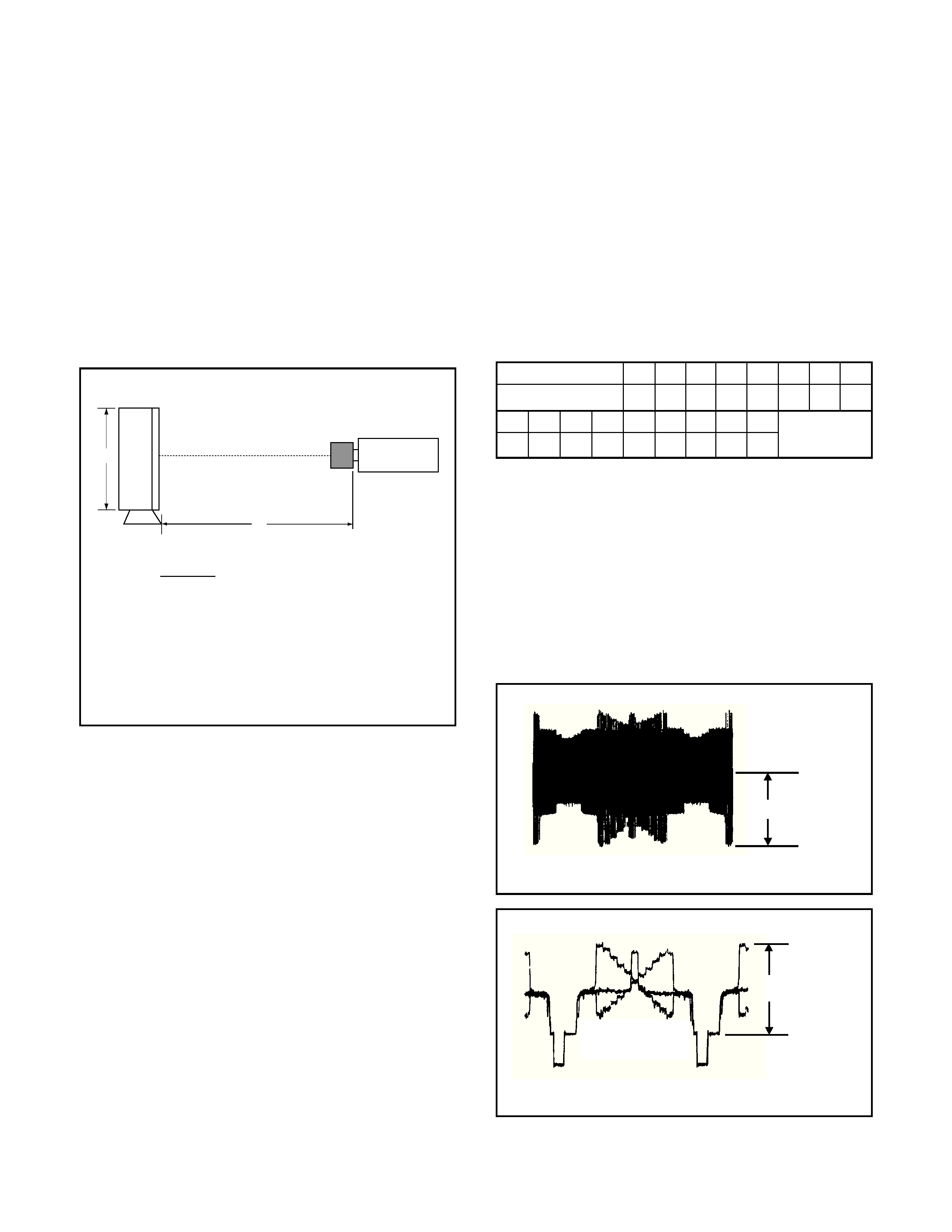
L: Distance from CS mount to pattern (mm)
H: Pattern height (mm)
f : Lens focal length (standard 12 mm)
h: Height (4.8 mm) of CCD imaging surface
Note : The video monitor should be an under-scan TV.
L
=
× f 12.5 mm
(H + h)2
H
× h
L
CS mount surface
CCD camera
3,100 K viewer
H
VSUB abbreviation
SUB voltage (V)
P
10.5
N
10.0
E
6.0
f
6.5
G
7.0
h
7.5
J
8.0
K
8.5
L
9.0
m
9.5
Q
11.0
R
11.5
S
12.0
T
12.5
U
13.0
V
13.5
W
14.0
SUB voltage value
± 0.1 V (below figure)
TP202
VIDEO OUTPUT
800
± 10 mVp-p
400
± 50 mVp-p