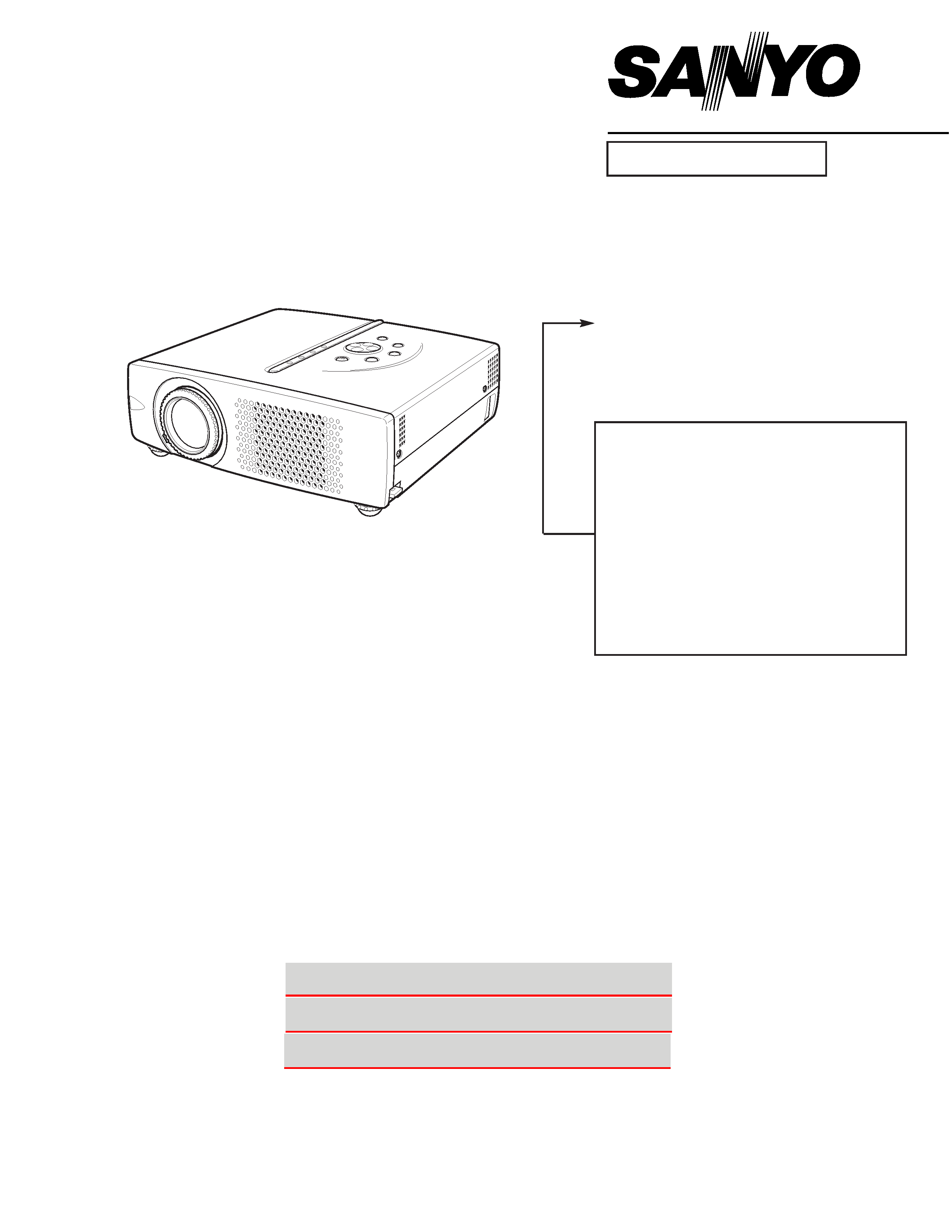
Multimedia Projector
SERVICE MANUAL
REFERENCE NO.
SM5110302-00
CONTENTS
Pages
TECHNICAL SPECIFICATIONS --------------------------------------------------------- 2 - 3
SAFETY INSTRUCTIONS --------------------------------------------------------------------- 4
LAMP REPLACEMENT------------------------------------------------------------------------- 5
PROTECTIONS----------------------------------------------------------------------------------- 6
MECHANICAL DISASSEMBLIES------------------------------------------------------ 7 - 11
ADJUSTMENT ---------------------------------------------------------------------------- 12 - 15
PIN DESCRIPTION OF DIODE, TRANSISTOR AND IC ----------------------------- 16
ELECTRICAL PARTS LIST ------------------------------------------------------------ 17 - 53
MECHANICAL PARTS LIST & ACCESSORIES --------------------------------- 54 - 55
SCHEMATIC DIAGRAMS------------------------------------------------------------ A1 - A12
PRINTED WIRING BOARD DIAGRAMS --------------------------------------- A13 - A14
FILE NO.
PRODUCT CODE
1 122 103 00 PLC-XW20 (MW6A)
1 122 104 00 PLC-XW20 (PW6A)
1 122 104 02 PLC-XW20 (PW6C)
1 122 112 00 PLC-SW20 (MZ6A)
1 122 113 00 PLC-SW20 (PZ6A)
1 122 113 02 PLC-SW20 (PZ6C)
ORIGINAL VERSION
Chassis No. MW6-XW2000
(PLC-XW20)
MZ6-SW2000
(PLC-SW20)
Model No. PLC-XW20
PLC-SW20
(U.S.A., Canada, Europe
Asia, Africa U.K.)
NOTE: Match the Chassis No. on the
unit's back cover with the Chassis
No. in the Service Manual.
If the Original Version Service
Manual Chassis No. does not
match the unit's, additional
Service Literature is required. You
must refer to "Notices" to the
Original Service Manual prior to
servicing the unit.
Service Instructions & Parts List
Schematic Diagrams
Printed Wiring Board Diagrams
This Service Manual is provided with the above
sections. Click the sections you wish.
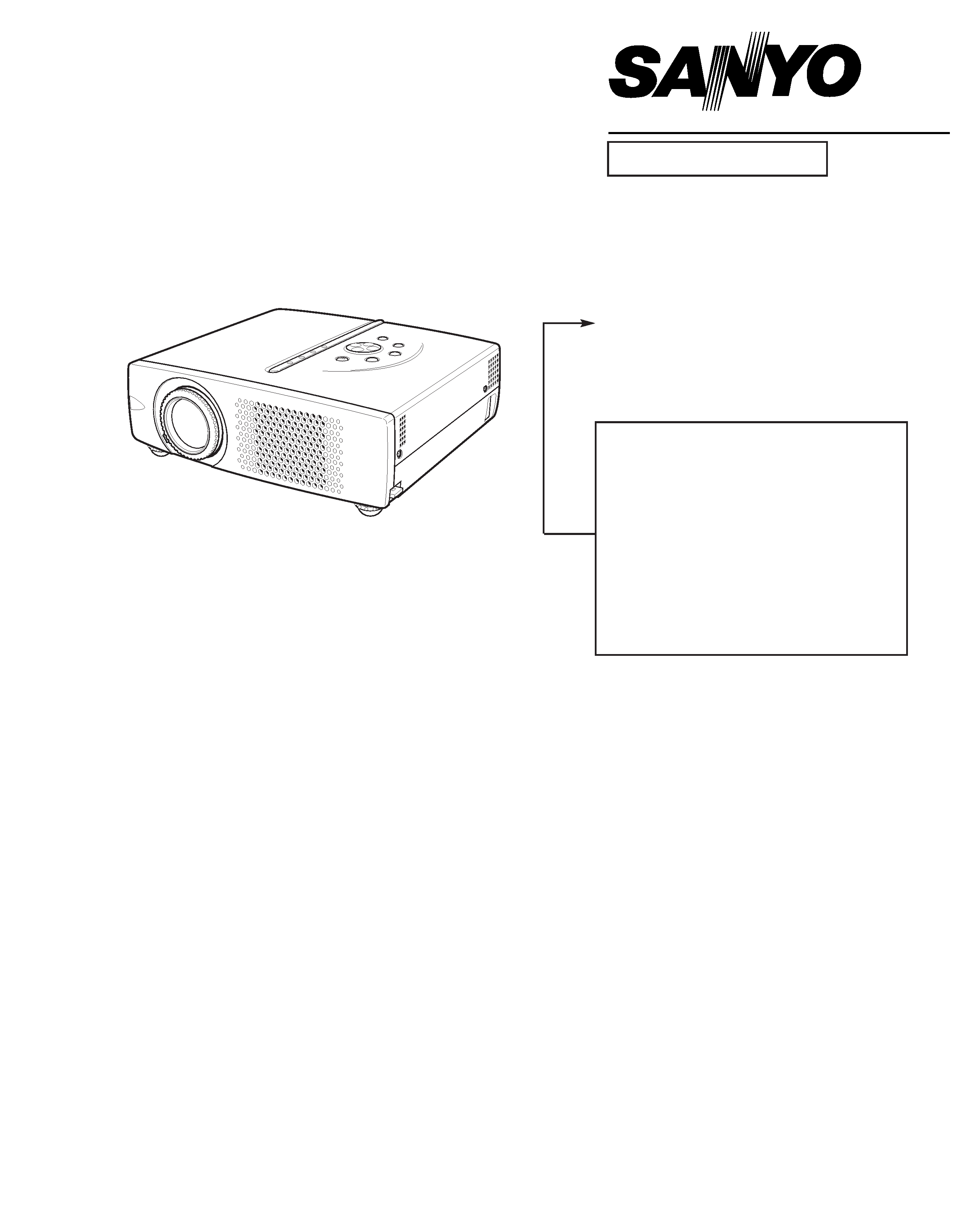
Multimedia Projector
SERVICE MANUAL
REFERENCE NO.
SM5110302-00
CONTENTS
Pages
TECHNICAL SPECIFICATIONS --------------------------------------------------------- 2 - 3
SAFETY INSTRUCTIONS --------------------------------------------------------------------- 4
LAMP REPLACEMENT------------------------------------------------------------------------- 5
PROTECTIONS----------------------------------------------------------------------------------- 6
MECHANICAL DISASSEMBLIES------------------------------------------------------ 7 - 11
ADJUSTMENT ---------------------------------------------------------------------------- 12 - 15
PIN DESCRIPTION OF DIODE, TRANSISTOR AND IC ----------------------------- 16
ELECTRICAL PARTS LIST ------------------------------------------------------------ 17 - 53
MECHANICAL PARTS LIST & ACCESSORIES --------------------------------- 54 - 55
SCHEMATIC DIAGRAMS------------------------------------------------------------ A1 - A12
PRINTED WIRING BOARD DIAGRAMS --------------------------------------- A13 - A14
FILE NO.
PRODUCT CODE
1 122 103 00 PLC-XW20 (MW6A)
1 122 104 00 PLC-XW20 (PW6A)
1 122 104 02 PLC-XW20 (PW6C)
1 122 112 00 PLC-SW20 (MZ6A)
1 122 113 00 PLC-SW20 (PZ6A)
1 122 113 02 PLC-SW20 (PZ6C)
ORIGINAL VERSION
Chassis No. MW6-XW2000
(PLC-XW20)
MZ6-SW2000
(PLC-SW20)
Model No. PLC-XW20
PLC-SW20
(U.S.A., Canada, Europe
Asia, Africa U.K.)
NOTE: Match the Chassis No. on the
unit's back cover with the Chassis
No. in the Service Manual.
If the Original Version Service
Manual Chassis No. does not
match the unit's, additional
Service Literature is required. You
must refer to "Notices" to the
Original Service Manual prior to
servicing the unit.
-2-
I Technical Specifications
I PLC-XW20
0.7" TFT Active Matrix type, 3 panels
Multi-media Projector
6.2lbs (2.8 kg)
10.12" x 2.98" x 9.02" (257mm x 75.8mm x 229mm) (not including Adjustble Feet and Lens)
1024 x 768 dots
2,359,296 (1024 x 768 x 3 panels)
PAL, SECAM, NTSC, NTSC4.43, PAL-M and PAL-N
H-sync. 15 ~ 100 KHz, V-sync. 50 ~ 100 Hz
Adjustable from 34" to 200"
550 TV lines
1 speaker, ø1.1" (28mm)
41 °F ~ 95 °F (5 °C ~ 35 °C)
14 °F ~ 140 °F (-10 °C ~ 60 °C)
Owner's Manual
AC Power Cord
Wireless Remote Control Transmitter and Battery
VGA Cable
Carrying Bag
Lens Cover
Projector Type
Net Weight
Dimensions (W x H x D)
Panel Resolution
Number of Pixels
Color System
Scanning Frequency
Projection Image size (Diagonal)
Horizontal Resolution
Built-in Speakers
Operating Temperature
Storage Temperature
Accessories
LCD Panel System
G The specifications are subject to change without notice.
F 1.6 ~ 1.78 lens with f 28.7 mm ~ 34.5 mm with manual zoom and focus
5.3' ~ 26.6' (1.6 m ~ 8.1 m)
150 W
RCA Type x 3 (Video/Y, Pb/Cb, Pr/Cr) and Mini DIN 4 pin x 1 (S-Video)
Projection Lens
Throw Distance
Projection Lamp
Video Input Jacks
Mini Jack (stereo) x 1
Audio Input Jacks
(VGA) HDB 15 Terminal x 1
Mini Jack (stereo) x 1
Mini DIN 8 pin x 1
Mini Jack (stereo) x 1
1.0 W RMS
Computer Input Terminals
Computer Audio Input Jack
Control Port Connector
Audio Output Jacks
Internal Audio Amp
0° to 10.6°
Feet Adjustment
Power Source
:
Lithium Type (CR2025 / 3.0V)
Operating Range
:
16.4' (5m) / ±30°
Dimensions
:
2.1" x 0.28" x 5.3" (54mm x 7mm x 135mm)
Net Weight
:
1.27oz (36 g) (including battery)
Remote Control Transmitter
480i, 480p, 575i, 575p, 720p, 1035i, and 1080i
High Definition TV Signal
USB Series B receptacle x 1
USB Connector
AC 100 ~ 120 V (2.8 A Max. Ampere), 50 / 60 Hz (The U.S.A and Canada)
AC 200 ~ 240 V (1.4 A Max. Ampere), 50 / 60 Hz (Continental Europe and The U.K.)
Voltage and
Power Consumption
-3-
I Technical Specifications
I PLC-SW20
0.7" TFT Active Matrix type, 3 panels
Multi-media Projector
6.2lbs (2.8 kg)
10.12" x 2.98" x 9.02" (257mm x 75.8mm x 229mm) (not including Adjustable Feet and Lens)
800 x 600 dots
1,440,000 (800 x600 x 3 panels)
PAL, SECAM, NTSC, NTSC4.43, PAL-M and PAL-N
H-sync. 15 ~ 80 KHz, V-sync. 50 ~ 100 Hz
Adjustable from 34" to 200"
500 TV lines (S-Video)
1 speaker, ø1.1" (28mm)
41 °F ~ 95 °F (5 °C ~ 35 °C)
14 °F ~ 140 °F (-10 °C ~ 60 °C)
Owner's Manual
AC Power Cord
Wireless Remote Control Transmitter and Battery
VGA Cable
Carrying Bag
Lens Cover
Projector Type
Net Weight
Dimensions (W x H x D)
Panel Resolution
Number of Pixels
Color System
Scanning Frequency
Projection Image size (Diagonal)
Horizontal Resolution
Built-in Speaker
Operating Temperature
Storage Temperature
Accessories
LCD Panel System
G The specifications are subject to change without notice.
F 1.6 ~ 1.78 lens with f 28.7 mm ~ 34.5 mm with manual zoom and focus
5.3' ~ 26.6' (1.6 m ~ 8.1 m)
150 W
RCA Type x 3 (Video/Y, Pb/Cb, Pr/Cr) and Mini DIN 4 pin x 1 (S-Video)
Projection Lens
Throw Distance
Projection Lamp
Video Input Jacks
Mini Jack (stereo) x 1
Audio Input Jacks
(VGA) HDB 15 Terminal x 1
Mini Jack (stereo) x 1
Mini DIN 8 pin x 1
Mini Jack (stereo) x 1
1.0 W RMS
Computer Input Terminals
Computer Audio Input Jack
Control Port Connector
Audio Output Jacks
Internal Audio Amp
0° to 10.6°
Feet Adjustment
Power Source
:
Lithium Type (CR2025 / 3.0V)
Operating Range
:
16.4' (5m) / ±30°
Dimensions
:
2.1" x 0.28" x 5.3" (54mm x 7mm x 135mm)
Net Weight
:
1.27oz (36 g) (including battery)
Remote Control Transmitter
480i, 480p, 575i, 575p, 720p, 1035i, and 1080i
High Definition TV Signal
USB Series B receptacle x 1
USB Connector
AC 100 ~ 120 V (2.8 A Max. Ampere), 50 / 60 Hz (The U.S.A and Canada)
AC 200 ~ 240 V (1.4 A Max. Ampere), 50 / 60 Hz (Continental Europe and The U.K.)
Voltage and
Power Consumption
-4-
I Safety Instructions
WARNING:
The chassis of this projector is isolated (COLD) from AC line by using the converter transformer. Primary side of
the converter and lamp power supply unit circuit is connected to the AC line and it is hot, which hot circuit is iden-
tified with the line (
) in the schematic diagram. For continued product safety and protection of personnel
injury, servicing should be made with qualified personnel.
The following precautions must be observed.
1: An isolation transformer should be connected in the power line between the projector and the AC line before any
service is performed on the projector.
2: Comply with all caution and safety-related notes provided on the cabinet back, cabinet bottom, inside the cabi-
net or on the chassis.
3: When replacing a chassis in the cabinet, always be certain that all the protective devices are installed proper-
ly, such as, control knobs, adjustment covers or shields, barriers, etc.
DO NOT OPERATE THIS PROJECTOR WITHOUT THE PROTECTIVE SHIELD IN POSITION AND PROPER-
LY SECURED.
4: Before replacing the cabinet cover, thoroughly inspect the inside of the cabinet to see that no stray parts or
tools have been left inside.
Before returning any projector to the customer, the service personnel must be sure it is completely safe to oper-
ate without danger of electric shock.
I SAFETY PRECAUTIONS
I PRODUCT SAFETY NOTICE
Product safety should be considered when a component replacement is made in any area of the projector.
Components indicated by mark
in the parts list and the schematic diagram designate components in which
safety can be of special significance. It is, therefore, particularly recommended that the replacement of the parts
must be made by exactly the same parts.
Eye damage may result from directly viewing the light produced by the Lamp used in this equipment. Always turn
off Lamp before opening cover. The Ultraviolet radiation eye protection is required during this servicing.
Never turn the power on without the lamp to avoid electric-shock or damage of the devices since the stabilizer
generates high voltages(20~25kV) at its starts.
Since the lamp is very high temperature during units operation. Replacement of the lamp should be done at least
45 minutes after the power has been turned off, to allow the lamp cool-off.
I SERVICE PERSONNEL WARNING
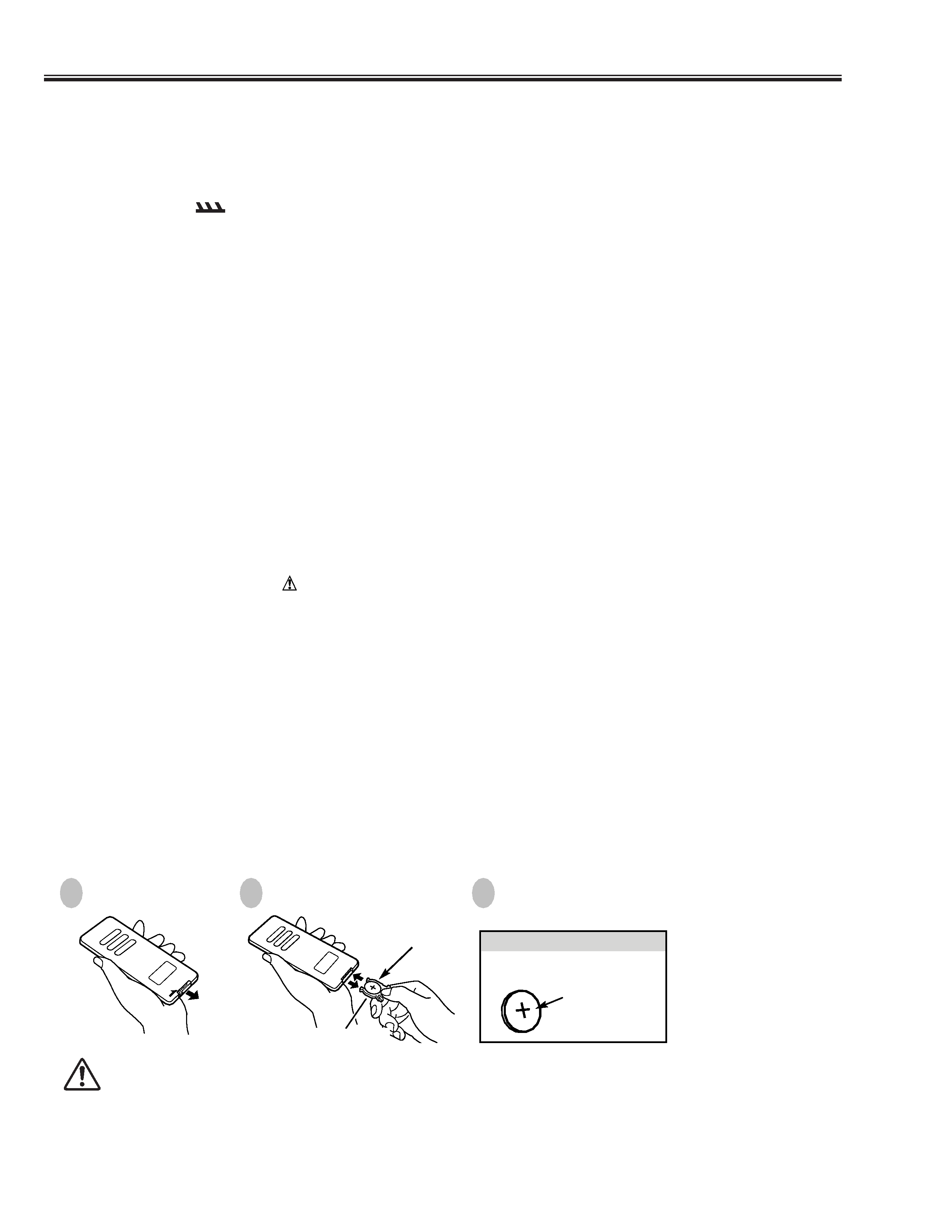
Pull out Battery Holder.
Replace with new battery. Install
with battery (+),() marks properly.
Install battery and
Battery Holder into
Remote Control Unit.
BATTERY
LITHIUM BATTERY
CR2025 (3.0V)
(+) mark indicates
its (+) polarity.
Put Battery + mark
as shown direction.
BATTERY HOLDER
To insure safe operation, please observe the following precautions :
G Use only specified battery. Improper battery may cause malfunction of Remote Control or a battery.
G Do not expose a battery to moisture or heat. Do not charge a battery.
G If a battery have leaked on Remote Cotrol Unit, carefully wipe the case clean and load a new battery.
G Be sure to install battery with correct polarity.
G Dispose used battery following local regulation.
G Danger of explosion if battery is incorrectly replaced. Replace only with the same or equivalent type
recommended by the manufacturer.
1
2
3
I REMOTE CONTROL BATTERY INSTALLATION