Specifications
Power Rating . . . . . . . . . . . . . . . . . . . . . . . . 120VAC
300W, 3.5A (Max)
Antenna Input Impedance . . . . . . . . . . . . . . . . . 75
UHF/VHF/CATV
Digital
Receiving Channel . . . . . . . . . . . . . . . . 2 - 13 (VHF),
14 - 69 (UHF),
01, 14-94, 95-125 (CATV)
1-99 (Digital)
Remote Ready . . . . . . . . . . 32 Key Remote Control
Sound Output . . . . . . . . . . . . . . . . . . . . . . 5.0 W/CH
Intermediate Frequency
Picture IF Carrier . . . . . . . . . . . . . . . . . . 45.75MHz
Sound IF Carrier . . . . . . . . . . . . . . . . . . 41.25MHz
Color Sub Carrier . . . . . . . . . . . . . . . . . 42.17MHz
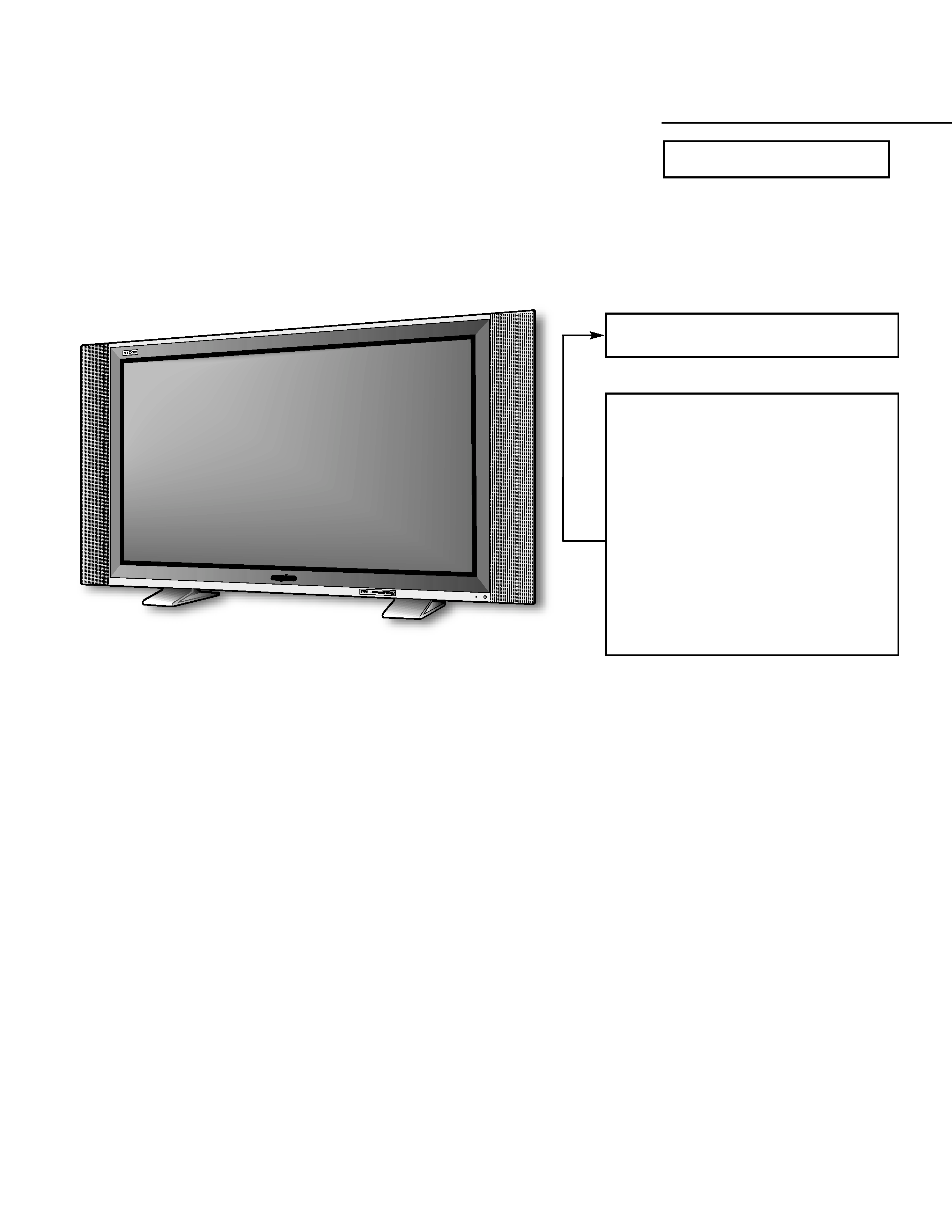
Cabinet Dimensions
Width . . . . . . . . . . . . . . . . . . . . . . . . . . . . 1206mm
Height . . . . . . . . . . . . . . . . . . . . . . . . . . . . 716mm
Depth including base . . . . . . . . . . . . . . . . 249mm
REFERENCE No.
SM780103
DP42545, J3TR, PRODUCT CODE 111008200
Contents
Safety Instructions . . . . . . . . . . . . . . . . . . 2
Service Adjustments . . . . . . . . . . . . 3 12
Power Failure Circuit . . . . . . . . . . . . . . . 13
Mechanical Disassemblies . . . . . . . 14 19
Chassis Electrical Parts List . . . . . . 20 - 34
Cabinet Parts List . . . . . . . . . . . . . . . . . . 35
Component and Test Point
Locations . . . . . . . . . . . . . . . . . . . 36 40
Block Diagrams . . . . . . . . . . . . . . . . 41 50
Trouble Shooting Flow Charts . . . . 51 53
Control Port Functions . . . . . . . . . . 54 55
Schematic Notes . . . . . . . . . . . . . . . . . . . 57
Pin Layouts. . . . . . . . . . . . . . . . . . . . . . . . 57
Capacitor and Resistor Codes . . . . . . . . 57
Board Connections . . . . . . . . . . . . . 58 60
Schematic Diagrams . . . . . . . . . . . . 61 72
AS
FILE NO.
SERVICE MANUAL
Remote Control Plasma
Color Television
DP42545 (U.S.A.)
(CANADA)
ORIGINAL VERSION
Chassis No. 42545-00
NOTE: Match the Chassis No. on
the unit's back cover with
the Chassis No. in the
Service Manual.
If the Original Version
Service Manual Chassis
No. does not match the
unit's, additional Service
Literature is required. You
must refer to "Notices" to the
Original Service Manual
prior to servicing the unit.
AS
-- 2 --
SAFETY PRECAUTIONS
WARNING: The chassis of this receiver has a floating
ground with the potential of one half the AC line voltage in
respect to earth ground. Service should not be attempted by
anyone not familiar with the precautions necessary when
working on this type of equipment.
The following precautions must be observed:
1. An isolation transformer must be connected in the power
line between the receiver and the AC line before any ser-
vice is performed on the receiver.
2. Comply with all caution and safety-related notes provid-
ed inside the cabinet, on the chassis, and on the back.
3. When replacing a chassis in the cabinet, always be certain
that all the protective devices are installed properly, such
as control knobs, adjustment covers, shields and barriers.
DO NOT OPERATE THIS TELEVISION RECEIVER
WITHOUT THE PROTECTIVE SHIELD IN POSITION AND
PROPERLY SECURED.
4. Before replacing the back cover of the set, thoroughly
inspect the inside of the cabinet to see that no stray parts
or tools have been left inside.
Before returning any television to the customer, the
service technician must perform the following safety
checks to be sure that the unit is completely safe to
operate without danger of electrical shock.
ANTENNA COLD CHECK
Remove AC plug from the 120 VAC outlet and place a
jumper across the two blades. Connect one lead of an ohm-
meter to the jumpered AC plug, and touch the other lead to
each exposed antenna terminal (UHF and VHF antenna ter-
minals). The resistance must measure between 1M ohm and
5.2M ohm. Any resistance value below or above this range
indicates an abnormality which requires corrective action.
PRODUCT SAFETY NOTICE
When replacing components in a receiver, always keep in
mind the necessary product safety precautions. Pay special
attention to the replacement of components marked with a
star (5) in the parts list and in the schematic diagrams. To
ensure safe product operation, it is necessary to replace
those components with the exact same PARTS.
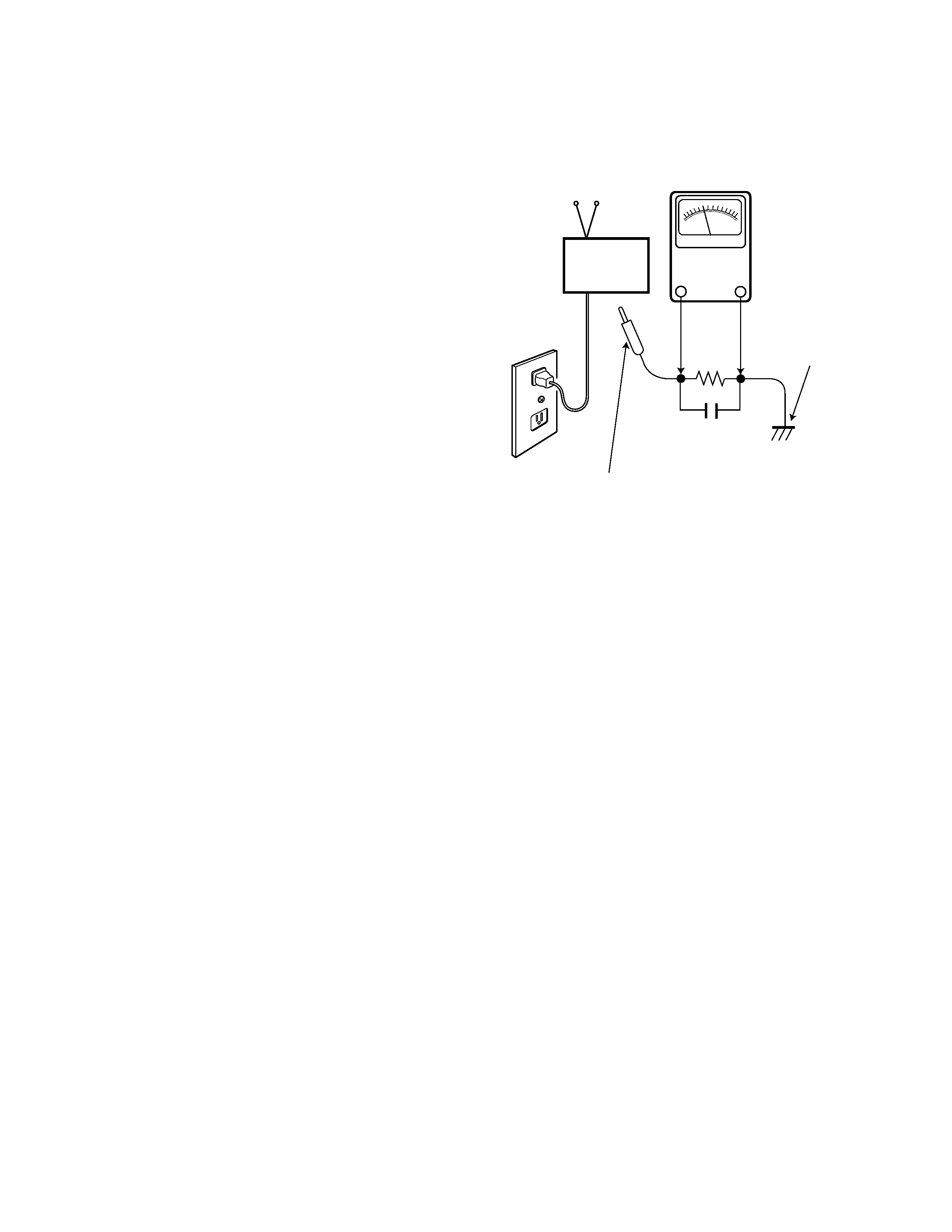
LEAKAGE CURRENT CHECK
Plug the AC line cord directly into a 120 VAC outlet. (Do not
use an isolation transformer for this check.) Use an AC volt-
meter, that has 5000 ohms per volt or more sensitivity.
Connect a 1500 ohm 10 watt resistor, paralleled by a 0.15 µF
150 VAC capacitor, between a known good earth ground
(water pipe, conduit, etc.) and all exposed metal parts of the
cabinet (antennas, handle bracket, metal cabinet, screw
heads, metal overlays, control shafts, etc.). Measure the AC
voltage across the 1500 ohm resistor. The AC voltage
should not exceed 750 mV. A reading exceeding 750 mV
indicates that a dangerous potential exists. The fault must
be located and corrected. Repeat the above test with the
receiver power plug reversed.
NEVER RETURN A RECEIVER TO THE CUSTOMER
WITHOUT TAKING THE NECESSARY CORRECTIVE ACTION.
0.15 µF 150V AC
1500 ohm
10 watt
Good earth ground
such as a water pipe,
conduit, etc.
AC OUTLET
TELEVISION
RECEIVER
READING SHOULD NOT EXCEED 750 mV.
AC VOLTMETER
(5000 ohms per volt or more sensitivity)
To be touched to all of exposed metal parts.
Voltmeter Hook-up for Leakage Current Check.
SAFETY INSTRUCTIONS
GENERAL
This set has an On-screen Service Menu system included in
the CPU that allows remote operation for most of the ser-
vice adjustments.
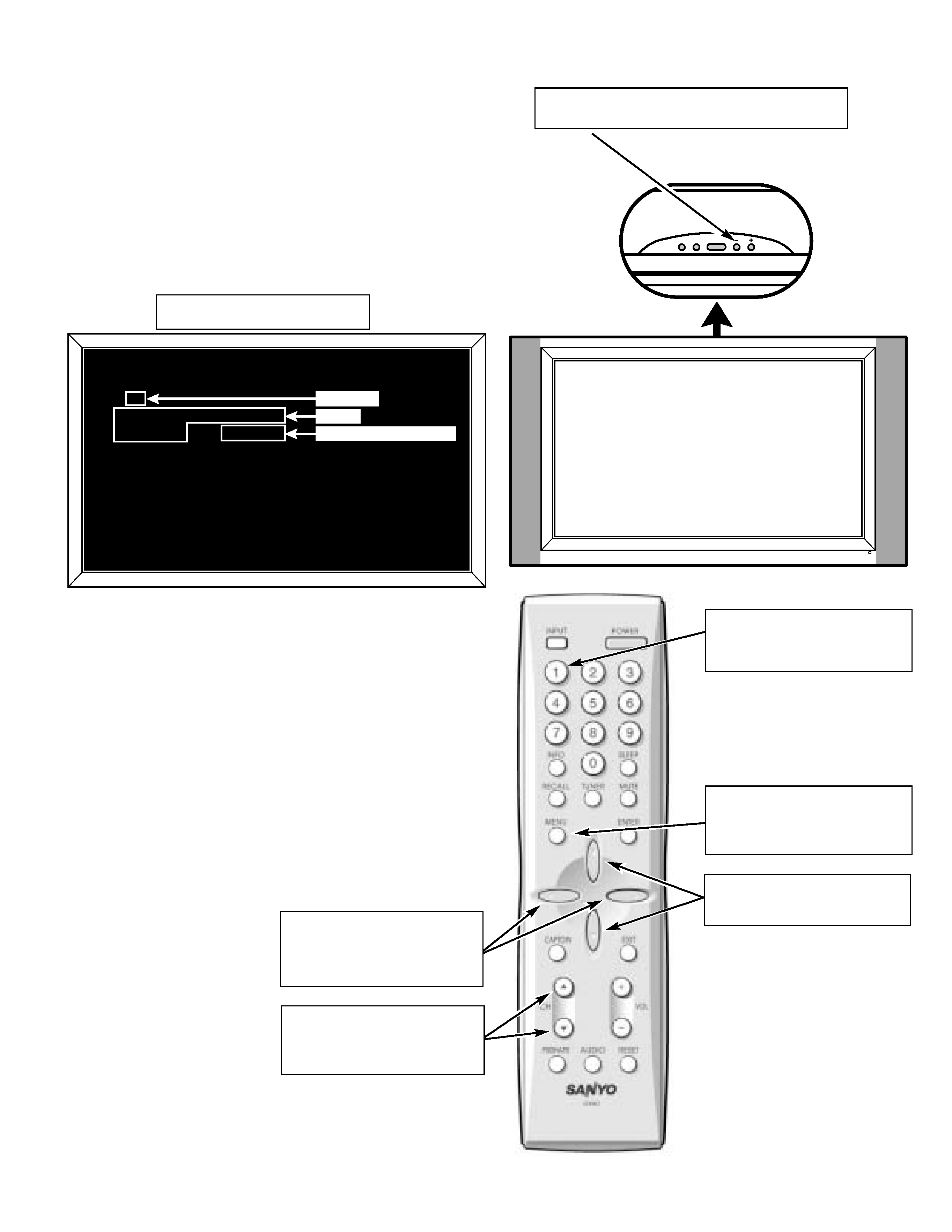
ON-SCREEN SERVICE MENU SYSTEM
1. Enter the Service Menu:
· While pressing the Volume () button on the televi-
sion, press the Number Key 1 on the remote control
unit. The Service Menu will now appear.
2. Service Adjustments:
· Press the Menu v or w key to select the desired ser-
vice menu item you want to adjust. See page 4 for
the On-screen Service Menu.
Note: Press the CH v or w key to skip up or down 10
items.
· Use the Menu < or > key to adjust the data.
The
< or > keys will increase or decrease the data
sequentially.
3. Exit from the Service Menu:
· Press the MENU key to turn off the Service Menu
display.
-- 3 --
SERVICE ADJUSTMENTS
Volume
: Enter Service Menu
Service Menu Display
__SERVICE
__0
W/B_B/B_________R_Drive
CVBS_W/B_______20 (_32)
_________________MP-001
L( 130)_M( 130)_S( 130)_S
APL(051%)(047%)_GAMMA(070_(50))
Item No.
Name
Data (Decimal Data)
POWER
VOL
CH
w
v
Number 1:
Enter Service Menu
Menu:
Exit Service Menu
v w: Select Item
< >:
Adjust Service Data
CH v w:
Skip 10 items

-- 4 --
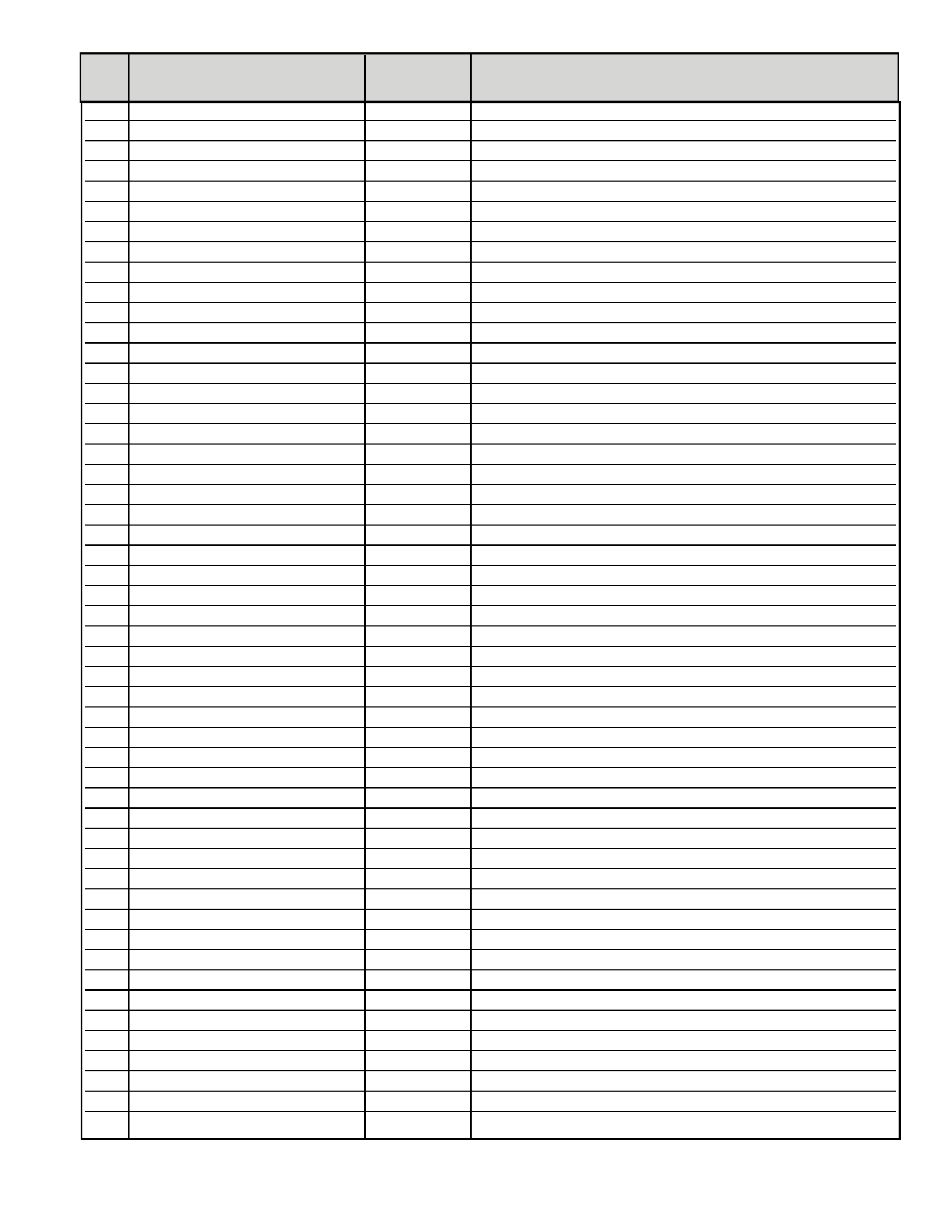
ON-SCREEN SERVICE MENU
No.
Name
Initial Data
Note
· All data except in gray box area is fixed. Do not change for correct operation.
· Data in gray box is initial. Can be set according to adjustment information.
000
CVBS/S_W/B__R Drive
20h
White Balance Adjustment (R), Composite/S Video
001
CVBS/S_W/B__G Drive
20h
White Balance Adjustment (G), Composite/S Video
002
CVBS/S_W/B__B Drive
20h
White Balance Adjustment (B), Composite/S Video
003
CVBS/S_B/B__R Cutoff
03h
Black Balance Adjustment (R), Composite/S Video
004
CVBS/S_B/B__G Cutoff
03h
Black Balance Adjustment (G), Composite/S Video
005
CVBS/S_B/B__B Cutoff
03h
Black Balance Adjustment (B), Composite/S Video
006
RF_W/B__R Drive
80h
W/B Adjustment (R), RF, Differential Data from CVBS/S
007
RF_W/B__G Drive
80h
W/B Adjustment (G), RF, Differential Data from CVBS/S
008
RF_W/B__B Drive
80h
W/B Adjustment (B), RF, Differential Data from CVBS/S
009
RF_B/B__R Cutoff
80h
B/B Adjustment (R), RF, Differential Data from CVBS/S
010
RF_B/B__G Cutoff
80h
B/B Adjustment (G), RF, Differential Data from CVBS/S
011
RF_B/B__B Cutoff
80h
B/B Adjustment (B), RF, Differential Data from CVBS/S
012
D1/D2_W/B__R Drive
80h
W/B Adjustment (R), D1/D2, Differential Data from CVBS/S
013
D1/D2_W/B__G Drive
80h
W/B Adjustment (G), D1/D2, Differential Data from CVBS/S
014
D1/D2_W/B__B Drive
80h
W/B Adjustment (B), D1/D2, Differential Data from CVBS/S
015
D1/D2_B/B__R Cutoff
80h
B/B Adjustment (R), D1/D2, Differential Data from CVBS/S
016
D1/D2_B/B__G Cutoff
80h
B/B Adjustment (G), D1/D2, Differential Data from CVBS/S
017
D1/D2_B/B__B Cutoff
80h
B/B Adjustment (B), D1/D2, Differential Data from CVBS/S
018
D3/D4_W/B__R Drive
80h
W/B Adjustment (R), D3/D4, Differential Data from CVBS/S
019
D3/D4_W/B__G Drive
80h
W/B Adjustment (G), D3/D4, Differential Data from CVBS/S
020
D3/D4_W/B__B Drive
80h
W/B Adjustment (B), D3/D4, Differential Data from CVBS/S
021
D3/D4_B/B__R Cutoff
80h
B/B Adjustment (R), D3/D4, Differential Data from CVBS/S
022
D3/D4_B/B__G Cutoff
80h
B/B Adjustment (G), D3/D4, Differential Data from CVBS/S
023
D3/D4_B/B__B Cutoff
80h
B/B Adjustment (B), D3/D4, Differential Data from CVBS/S
024
DIGITAL_W/B__R Drive
80h
W/B Adjustment (R), Digital, Differential Data from CVBS/S
025
DIGITAL_W/B__G Drive
80h
W/B Adjustment (G), Digital, Differential Data from CVBS/S
026
DIGITAL_W/B__B Drive
80h
W/B Adjustment (B), Digital, Differential Data from CVBS/S
027
DIGITAL_B/B__R Cutoff
80h
B/B Adjustment (R), Digital, Differential Data from CVBS/S
028
DIGITAL_B/B__G Cutoff
80h
B/B Adjustment (G), Digital, Differential Data from CVBS/S
029
DIGITAL_B/B__B Cutoff
80h
B/B Adjustment (B), Digital, Differential Data from CVBS/S
030
Mode_Mode-1
0Ah
Bank_2 Setting
031
Mode_Mode-2A
03h
Bank_2 Setting
032
Mode_Mode-2B
0Fh
Bank_2 Setting
033
Mode_Mode-3A
06h
Bank_2 Setting
034
Mode_Mode-3B
00h
Bank_2 Setting
035
Sub Image_CVBS/S_Contrast
22h
036
Sub Image_CVBS/S_Bright
6Ah
037
Sub Image_CVBS/S_Color
58h
038
Sub Image_CVBS/S_Tint
40h
039
Sub Image_CVBS/S_H_Sharp
15h
040
Sub Image_CVBS/S_Sub_Sharp
13h
041
Sub Image_CVBS/S_H_Detail
00h
042
Sub Image_CVBS/S_H_Shoot
10h
043
Sub Image_CVBS/S_H_Coring
05h
044
Sub Image_CVBS/S_H_PeakF
05h
045
Sub Image_CVBS/S_V_Sharp
01h
046
Sub Image_CVBS/S_V_Coring
02h
047
Sub Image_CVBS/S_V_Pairing
04h
048
Sub Image_CVBS/S_V_Vlinsw
01h
049
Sub Image_CVBS/S_3DYCSh
00h
050
Sub Image_CVBS/S_Filter_1
03h
051
Sub Image_CVBS/S_Filter_2
01h
052
Sub Image_RF_Contrast
22h
053
Sub Image_RF_Bright
6Ah
054
Sub Image_RF_Color
58h
055
Sub Image_RF_Tint
40h
056
Sub Image_RF_H_Sharp
15h
057
Sub Image_RF_Sub_Sharp
13h
058
Sub Image_RF_H_Detail
00h
059
Sub Image_RF_H_Shoot
10h
060
Sub Image_RF_H_Coring
05h
061
Sub Image_RF_H_PeakF
05h
062
Sub Image_RF_V_Sharp
03h
063
Sub Image_RF_V_Coring
02h
064
Sub Image_RF_V_Pairing
04h
065
Sub Image_RF_V_Vlinsw
01h
066
Sub Image_RF_3DYCSh
00h
067
Sub Image_RF_Filter_1
03h
068
Sub Image_RF_Filter_2
01h
069
Sub Image_D1_Contrast
23h
070
Sub Image_D1_Bright
6Ah
071
Sub Image_D1_Color
3Dh
072
Sub Image_D1_Tint
40h
073
Sub Image_D1_H_Sharp
0Fh
074
Sub Image_D1_Sub_Sharp
10h
075
Sub Image_D1_H_Detail
00h
076
Sub Image_D1_H_Shoot
10h
077
Sub Image_D1_H_Coring
10h
078
Sub Image_D1_H_PeakF
55h
079
Sub Image_D1_V_Sharp
01h
080
Sub Image_D1_V_Coring
02h
081
Sub Image_D1_V_Pairing
04h
082
Sub Image_D1_V_Vlinsw
01h
083
Sub Image_D1_Filter_1
03h
084
Sub Image_D1_Filter_2
01h
085
Sub Image_D2_Contrast
24h
086
Sub Image_D2_Bright
80h
087
Sub Image_D2_Color
64h
088
Sub Image_D2_Tint
3Fh
089
Sub Image_D2_H_Sharp
0Fh
090
Sub Image_D2_Sub_Sharp
10h
091
Sub Image_D2_H_Detail
00h
092
Sub Image_D2_H_Shoot
10h
093
Sub Image_D2_H_Coring
05h
094
Sub Image_D2_H_PeakF
55h
095
Sub Image_D2_V_Sharp
01h
096
Sub Image_D2_V_Coring
02h
-- 5 --
No.
Name
Initial Data
Note