Part No.
SKSM0380
F7YVV
SEPTEMBER 2000
Colour Television
Service Manual
Model CE32WN3-C
Service Ref. No. CE32WN3-C-00
PRODUCT CODE: 111340316
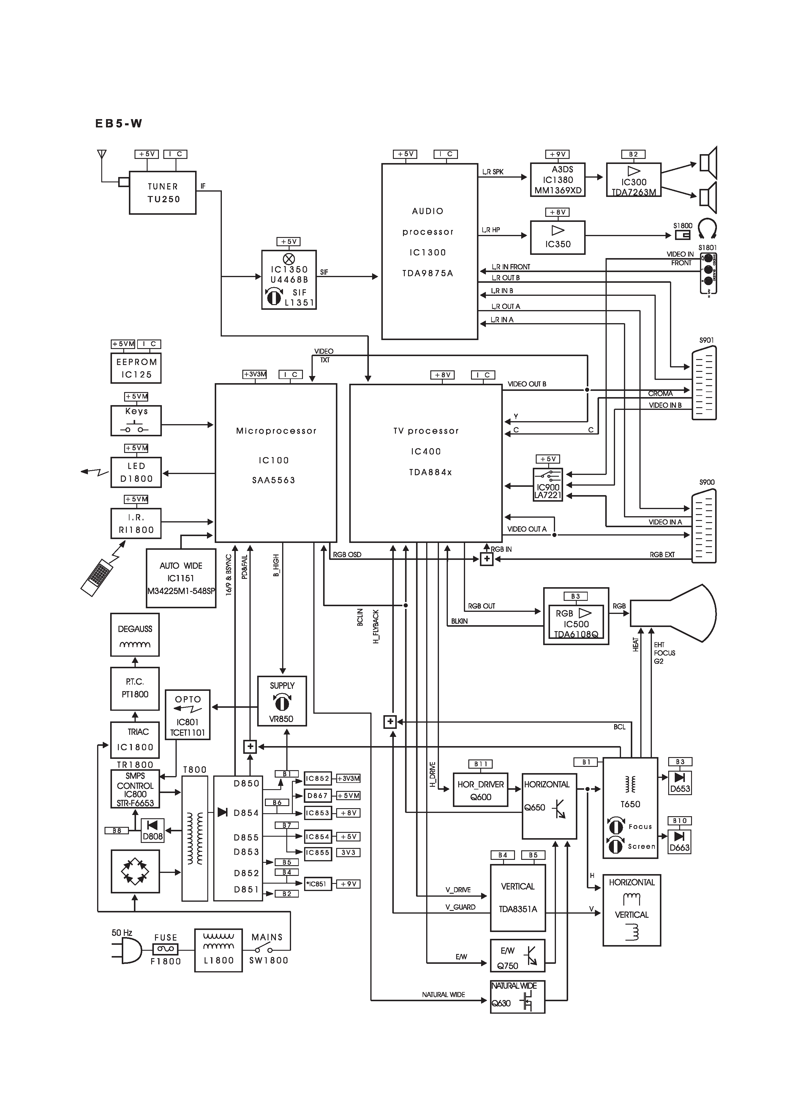
ORIGINAL VERSION: Chassis No. EB5-W
Give complete "SERVICE REF. NO." for parts
order or servicing, it is shown on the rating sheet
on the cabinet back of the TV set.
Note
This TV receiver will not work properly in foreign
countries where the television transmission
system and power source differ from the design
specifications. Refer to the specifications for the
design specifications
CE
32WN3-C
Contents
Safety precautions/Specifications . . . . . . . . . . . . . . . . . . . . . . . . . . . . . . . . . . . . . . . . . . . . . . . . . . .2
Block diagram . . . . . . . . . . . . . . . . . . . . . . . . . . . . . . . . . . . . . . . . . . . . . . . . . . . . . . . . . . . . . . . . . .3
Factory Special Mode/"HOTEL" & "RENTAL" Modes/Automatic Channel Search Reset (P&P)/Service Menu . . . . .4
Service Menu Tree . . . . . . . . . . . . . . . . . . . . . . . . . . . . . . . . . . . . . . . . . . . . . . . . . . . . . . . . . . . . . .5
Service Parameters Description . . . . . . . . . . . . . . . . . . . . . . . . . . . . . . . . . . . . . . . . . . . . . . . . . . . .6
Adjustment and Repair Procedures . . . . . . . . . . . . . . . . . . . . . . . . . . . . . . . . . . . . . . . . . . . . . . . . . .7
Switch-on Sequence/Protect modes and Failure indication/Protect mode inhibition/
Power Supply Repair Procedure/Non-Volatile memory (NVM) Replacement, IC125 . . . . . . . . . . . . . .8
Cabinet Disassembly . . . . . . . . . . . . . . . . . . . . . . . . . . . . . . . . . . . . . . . . . . . . . . . . . . . . . . . . . . . .9
Cabinet Parts List . . . . . . . . . . . . . . . . . . . . . . . . . . . . . . . . . . . . . . . . . . . . . . . . . . . . . . . . . . .10~11
TV Stand Parts List . . . . . . . . . . . . . . . . . . . . . . . . . . . . . . . . . . . . . . . . . . . . . . . . . . . . . . . . . . . . .12
Electric Parts List . . . . . . . . . . . . . . . . . . . . . . . . . . . . . . . . . . . . . . . . . . . . . . . . . . . . . . . . . . .13~21
-2-
F7YVV
SAFETY PRECAUTION
X-RADIATION PRECAUTION
The primary source of X-RADIATION in the television receiver is the picture tube. The picture tube is specially
constructed to limit X-RADIATION emissions. For continued X-RADIATION protection, the replacement tube
must be the same type as the original including suffix letter. Excessive high voltage may produce potentially
hazardous X-RADIATION. To avoid such hazards, the high voltage must be maintained within specified limit.
Refer to this service manual, high voltage adjustment for specific high voltage limit. If high voltage exceeds
specified limits, take necessary corrective action. Carefully follow the instructions for +B1 volt power supply
adjustment, and high voltage adjustment to maintain the high voltage within the specified limits.
PRODUCT SAFETY NOTICE
SPECIFICATIONS
Product safety should be considered when a component replacement is made in any area of a receiver.
Components indicated by mark
in the parts list and the schematic diagram designate components in which
safety can be of special significance. It is particularly recommended that only parts designated on the parts list in
this manual be used for component replacement designated by mark
. No deviations from resistance wattage
or voltage ratings may be made for replacement items designated by mark
.
!
!
!
1: An isolation transformer should be connected in the
power line between the receiver and the AC line
when a service is performed on the primary of the
converter transformer of the set.
2: Comply with all caution and safety-related notes
provided on the cabinet back, inside the cabinet, on
the chassis or the picture tube.
3: When replacing a chassis in the cabinet, always be
certain that all the protective devices are installed
properly, such as, control knobs, adjustment covers
or shields, barriers, isolation resistor-capacitor networks
etc. Before returning any television to the customer,
the service technician must be sure that it is completely
safe to operate without danger of electrical shock.
Power source
AC 220~240V, 50Hz
Television system
System B/G
Colour system
PAL
Receiving channel
UHF: #21~69
VHF: A~J
CATV: S1~S41, X, Y, Z
Aerial input impedance
75ohm
AV terminal
21 Pin SCART Terminal
AV1:CENELEC standard (S-Video Input)
AV2:CENELEC standard
Sound output(Music)
16 watts x 2
Dimensions (WxHxD)
876 x 584 x 556mm
Weight
46.3 Kg
-3-
F7YVV
2
2
2
2
2
220-240V
CRT
FBT
BLOCK DIAGRAM
This is a diagram for all models and therefore differs slightly from the actual block diagram.

-4-
F7YVV
Factory special mode
The Factory mode is a special TV working mode intend-
ed to help in the manufacturing process and it is identi-
fied on the screen with the message "FAC". This mode is
not suitable for customer use.
The main differences in respect to normal mode are:
1. Stand-by is always disabled.
2. Blue-back (no sync. signal present) is disabled.
3. Customer adjustments ( volume, contrast ...) work
four times faster.
4. `Cosmetic' delays are skipped out.
In case of finding the TV set in Factory mode, it must be
taken out of this state. To do so, just enter and exit the
user clock setting menu.
"HOTEL" and "RENTAL" modes
This two special modes are intended to be used in
hotels, hospitals and similar with the purpose to avoid
the manipulation of the basic TV settings. They are
stored in NVM, so they are kept even though the TV set
is disconnected from the mains.
Its main features are:
1. Maximum volume level is limited to the volume
chosen when the mode is entered.
2. Tuning operations are disabled.
3. The TV set always switches on with the normalisation
settings and users can not memorise any of their
personal preferences.
4. Language selection and child lock are disabled.
5. It is possible to force the TV set to always switch-on
in a selected program between 1 and 8 or in AV1.
To activate this mode, hold down the "VOL -" front key
and simultaneously press the "RECALL" remote control
key. The message " HOTEL: 00 " will appear waiting for
two digits entry.
The first digit indicates the selected mode:
`0': normal mode
`1': HOTEL mode
`2': RENTAL mode
The second digit indicates the program in which the set
will switch on:
`0': the same as it was selected when the TV set was
switched off (normal mode)
`1' to `8': always this programme selection (1 to 8).
`9': always AV1 mode
The `RENTAL' mode has the same features as the
`HOTEL' mode and additionally only the Vol+/- front keys
are available so it is only possible to change program
with the remote control. In order to exit from this mode,
the colour saturation level must be set to zero.
Automatic channel search reset (P & P)
In order to reset the initial automatic channel search
function, start a channel search in AUTO mode from the
user tuning menu and switch-off the TV set before any
station is found. The next time the TV set is switched on,
it will start an automatic channel-search.
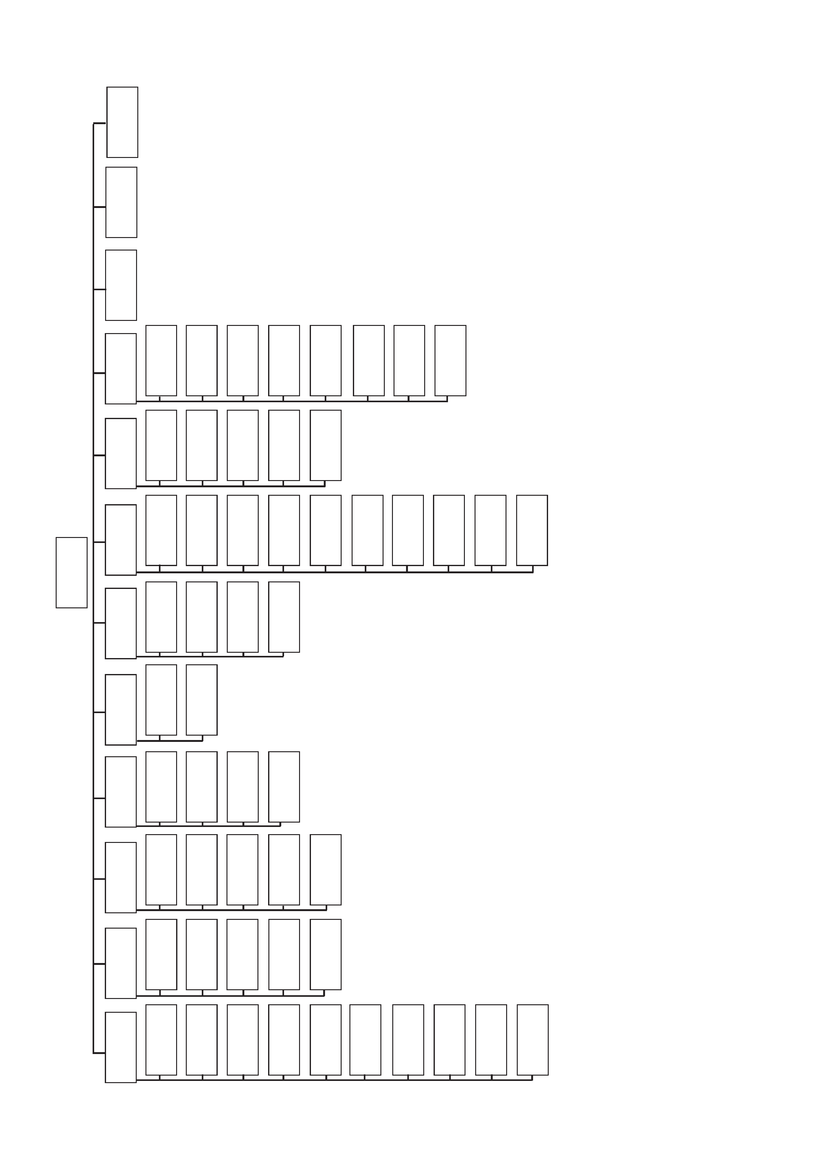
Service menu
The service menu is accessed by holding down the front
key "VOL-" and simultaneously pressing the teletext
GREEN key from the remote control. The service menu
is a two level structure as shown in the next page
diagram.
The active keys (local or remote) in service mode are:
VOL-, VOL+, P-, P+, MENU and the digits. The naviga-
tion through this menu works the same than in the user
menu.
* The P+ and P- keys allow to navigate through the
options in the active menu.
* The VOL+ key opens the second level menu if avail-
able. If there is a highlighted adjustment, the VOL- and
VOL+ keys allow to change it.
* The MENU key goes back one level menu. If the active
menu is the main one, it exits the service mode.
* The digit keys allow direct entry for adjustments.
* The SERVICE mode is exited by pressing any other
key.
-5-
F7YVV
SERVICE MENU TREE
GEOM
4:3
HOR
SHIFT
EW
AMPLIT
P
ARABO-
LA
CORNER
PA
R
TRAPEZI-
UM
CENTR
TXT
VERT
SLOPE
VERT
AMPL
S-CORREC
VERT
SHIFT
GEOM
16:9
GEOM
NA
TW
VIF
WHITE
G2
MORE
CONFIG
ST
ANDARD
V
-S
TAT
S-ST
A
T
I2C
BUS
SER
VICE
EW
AMPLI
P
ARABO-
LA
CORNER
PA
R
TRAPEZI-
UM
HOR
SHIFT
EW
AMPLI
P
ARABO-
LA
CORNER
PA
R
TRAPEZI-
UM
VERT
ZOOM
PLL
PLL
L
'
AGC
FFI
GREEN
BLUE
BRI
ADJ
AKB
K-DR
V
Y/C
P
A
L
Y/C
SECAM
Y/C
NTSC
Y/C
A
V
PBL
SPEED
CONTR
OSD
CONTR
TXT
SEMI
MUTE
AUT
OW
THR
INI
NVM
SECAM
L
NTSC
4.43
NTSC
M
CMB
TXEAST
OSO
OEM
UKMKT
PA
L
B
G
PA
L
D
K
PA
L
I
SECAM
BG
SECAM
DK