Colour Television
Service Manual
Give complete "SERVICE REF. NO." for parts
order or servicing, it is shown on the rating sheet
on the cabinet back of the TV set.
Note
This TV receiver will not work properly in foreign
countries where the television transmission
system and power source differ from the design
specifications. Refer to the specifications for the
design specifications
Contents
Safety precautions/Specifications . . . . . . . . . . . . . . . . . . . . . . . . . . . . . . . . . . . . . . . . . . . . . . . . . . . . . .2
Electrical Differences Parts List . . . . . . . . . . . . . . . . . . . . . . . . . . . . . . . . . . . . . . . . . . . . . . . . . . . . . . .3
Model CE28SN3-C
Service Ref.No.: CE28SN3-C-13
PRODUCT CODE: 111328207
SERVICE MANUAL SUPPLEMENT
Chassis No.: EB4-A (MKII)
Part No. SKSM0345
F2ZHY
November 1999
CE
28SN3-C
SERVICE MANUAL SUPPLEMENT
FOR ALL INFORMATION NOT CONTAINED IN THIS
SUPPLEMENT PLEASE REFER TO THE ORIGINAL
SERVICE MANUAL FOR CE28SN3-C-12. THIS
SUPPLEMENT ONLY CONTAINS DIFFERENCES
BETWEEN SERVICE REFERENCE NUMBERS.
SERVICE MANUAL SUPPLEMENT
THIS SUPPLEMENT SHOULD BE FILED WITH THE
ORIGINAL SERVICE MANUAL FOR CE28SN3-C-12.
-2-
EB4 MKII chassis
SAFETY PRECAUTION
X-RADIATION PRECAUTION
The primary source of X-RADIATION in the television receiver is the picture tube. The picture tube is specially
constructed to limit X-RADIATION emissions. For continued X-RADIATION protection, the replacement tube must
be the same type as the original including suffix letter. Excessive high voltage may produce potentially hazardous
X-RADIATION. To avoid such hazards, the high voltage must be maintained within specified limit. Refer to this
service manual, high voltage adjustment for specific high voltage limit. If high voltage exceeds specified limits,
take necessary corrective action. Carefully follow the instructions for +B1 volt power supply adjustment, and high
voltage adjustment to maintain the high voltage within the specified limits.
PRODUCT SAFETY NOTICE
PRODUCT SPECIFICATIONS
Product safety should be considered when a component replacement is made in any area of a receiver.
Components indicated by mark
in the parts list and the schematic diagram designate components in which
safety can be of special significance. It is particularly recommended that only parts designated on the parts list in
this manual be used for component replacement designated by mark
. No deviations from resistance wattage
or voltage ratings may be made for replacement items designated by mark
.
!
!
!
1: An isolation transformer should be connected in the
power line between the receiver and the AC line
when a service is performed on the primary of the
converter transformer of the set.
2: Comply with all caution and safety-related notes
provided on the cabinet back, inside the cabinet, on
the chassis or the picture tube.
3: When replacing a chassis in the cabinet, always be
certain that all the protective devices are installed
properly, such as, control knobs, adjustment covers
or shields, barriers, isolation resistor-capacitor
networks etc.Before returning any television to the
customer, the service technician must be sure that it
is completely safe to operate without danger of
electrical shock.
Power source
AC 220~240V, 50Hz
Television system
System B/G
Colour system
PAL/NTSC 4.43
Receiving channel
VHF: E2-E12
CATV: X, Y, Z, S1-S41
UHF: #21~69
Aerial input impedance
75 ohm
AV terminal
21 Pin socket
AV1: CENELEC standard (with RGB/S-inputs)
AV2: CENELEC standard
AV2: RCA Terminal, Video anf Audio (L/R) input
Sound output (Music)
12 watts x 2
Picture tube
70cm diagonal, 110 degree
(Visible picture diagonal)
66cm
Dimensions (WxHxD)
628 x 567 x 469mm
Weight
30.4 Kg
-3-
F2ZHY
Service Ref No.: CE28SN3-C-13
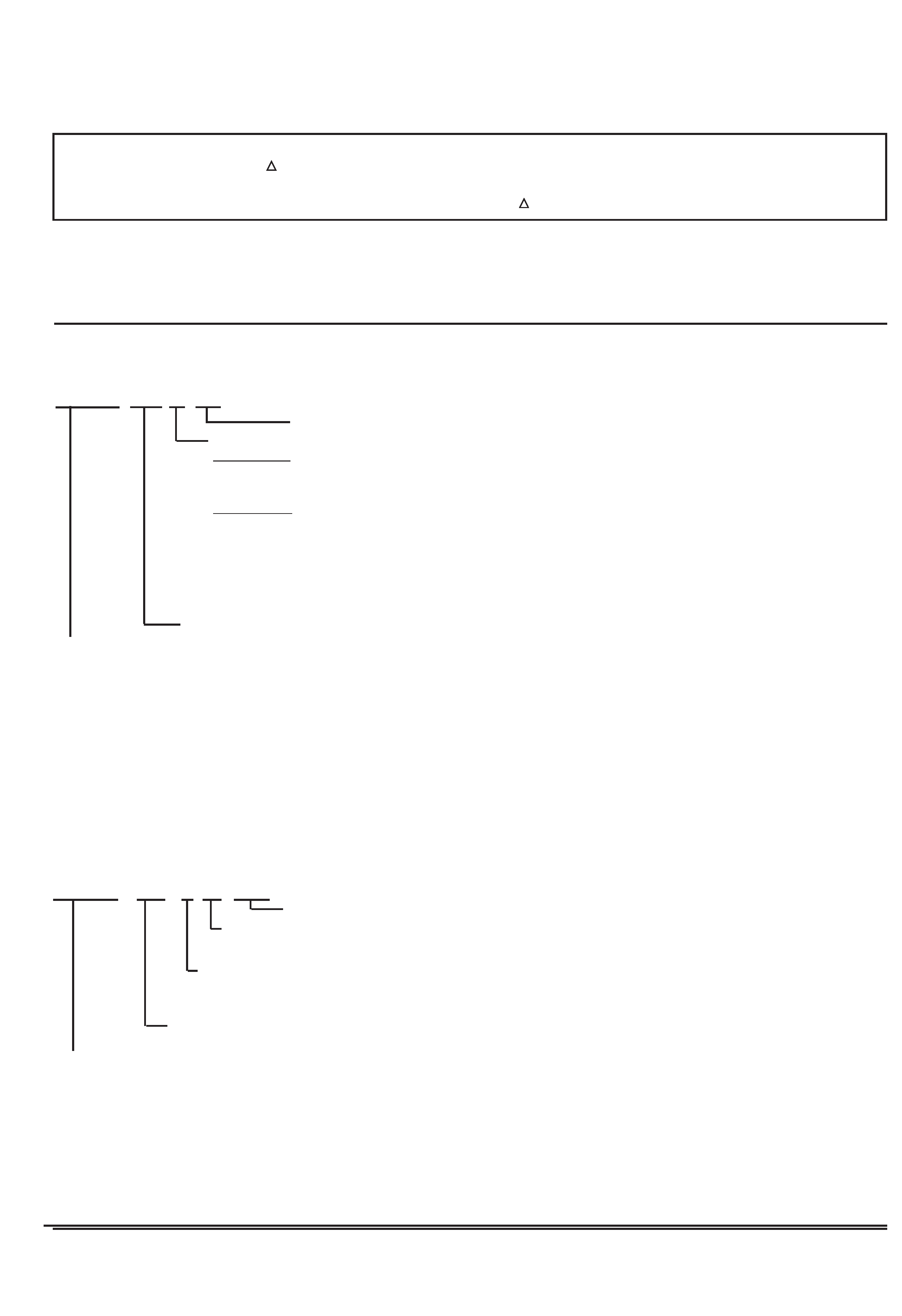
Chassis construction
OUT OF CIRCUIT
ASSY,PWB,CRT-MK2
1AA0B10H03500
ASSY,PWB,SIF
1AA0B10H030GA
ASSY,PWB,AUDIO
1AA0B10H030GB
ASSY,PWB,MAIN F2ZHY
1AA0B10H028A0
ASSY,PWB,AUDIO
1AA0B10H030GB
(SAME AS 1AA0B10H0300B EXCEPT FOR THE
FOLLOWING DIFFERENCES)
INTEGRATED CIRCUIT
IC3451
409 418 2901
IC TDA9875/V1
CAPACITOR
C3451
403 051 0607
ELECT
4.7U M
50V
C3452
403 069 9510
CERAMIC CHIP 0.01 Z
50V
C3462
403 012 6818
CERAMIC
15P J
50V
C3463
403 012 6818
CERAMIC
15P J
50V
C3465
403 073 1210
CERAMIC
0.033U K
50V
C3466
403 279 4312
CERAMIC
0.33U K
16V
C3475
403 248 1618
ELECT
47U M
16V
C3476
403 069 9510
CERAMIC CHIP 0.01 Z
50V
C3478
403 018 7413
CERAMIC
220P J
50V
C3479
403 018 7413
CERAMIC
220P J
50V
RESISTOR
R3461
401 038 5310
MT-GLAZE
39K JA 1/10W
R3462
401 037 5618
MT-GLAZE
10K JA 1/10W
R3463
401 038 0216
MT-GLAZE
20K JA 1/10W
R3472
401 038 2012
MT-GLAZE
270 JA 1/10W
COIL
L3451
1AV4L2C42R2KJ
PEAKING COIL 2.2U
L3452
1AV4L2C43R3KJ
PEAKING COIL 3.3U
L3453
1AV4L2C42R2KJ
PEAKING COIL 2.2U
DIODE
D3451
407 169 7919
VARACTOR DI BBY31
Ref. No.
Part No.
Description
CHASSIS ELECTRICAL PARTS LIST
Note: Parts order must contain Service Ref. No., Part No., and descriptions.
Product safety should be considered when a component replacement is made in any area of a receiver.
Components indicated by a
mark in this parts list and the circuit diagram show components whose value have
special significance to product safety. It is particularly recommended that only parts specified on the following parts
list be used for components replacement pointed out by the mark
.
!
!
Read description in the Capacitor and Resistor as follows:
CAPACITOR
CERAMIC 100P K 50V
Rated Voltage
Tolerance Symbols:
Less than 10PF
A: Not specified B: ±0.1PF
C: ±0.25PF
D: ±0.5PF
F: ±1PF
G: ±2PF
R: ±0.25-0PF
S: ±0-0.25PF E: +0-1PF
More than 10PF
A: Not specified B: ±0.1%
C: ±0.25%
D: ±0.5%
F: ±1%
G: ±2%
H: ±3%
J: ±5%
K: ±10%
L: ±15%
M: ±20%
N: ±30%
P: +100-0%
Q: +30-10%
T: +50-10%
U: +75-10%
V: +20-10%
W: +100-10%
X: +40-20%
Y: +150-10%
Z: +80-20%
Rated value: P=pico farad, U=Micro farad
Material:
CERAMIC.......... Ceramic
MT-PAPER........ Metallized Paper
POLYESTER..... Polyester
MT-POLYEST.... Metallized Polyester
POLYPRO.......... Polypropylene
MT-POLYPRO.... Metallized Polypropylene
COMPO FILM..... Composite film
MT-COMPO........ Metallized Composite
STYRENE........... Styrene
TA-SOLID........... Tantalum Solid
AL-SOLID........... Aluminium Solid
ELECT................ Electrolytic
NP-ELECT.......... Non-polarised Electrolytic
OS-SOLID.......... Aluminium Solid with Organic Semiconductive Electrolytic
DL-ELECT.......... Double Layered Electrolytic
RESISTOR
CARBON
4.7K
J
A
1/4W
Rated Wattage
Performance Symbols:
A: General B: Non flammable Z: Low noise
Other: Temperature coefficient
Tolerance Symbols:
A: ±0.05% B: ±0.1% C: ±0.25% D: ±0.5%
F: ±1%
G: ±2%
J: ±5%
K: ±10%
M: ±20%
P: +5-15%
Rated value, ohms:
K: 1,000, M: 1,000,000
Material:
CARBON........... Carbon
MT-FILM............ Metal Film
OXIDE-MT......... Oxide Metal Film
SOLID................ Composition
MT-GLAZE......... Metal Glaze
WIRE WOUND... Wire Wound
CERAMIC RES.. Ceramic
FUSIBLE RES.... Fusible

-4-
F2ZHY
Printed in UK
Sanyo Industries (UK) Ltd