PART No. SKSM0152
F2JE
Colour Television
Service Manual
Model C28WP1(Europe)
C28WP1B (U.K)
C28WP1E (Ireland)
Service Ref. No. C28WP1-00
Service Ref. No. C28WP1B-00
Service Ref. No. C28WP1E-00
Give complete "SERVICE REF. NO." for parts order or
servicing, it is shown on the rating sheet on the
cabinet back of the TV set.
Note
This TV receiver will not work properly in foreign
countries where the television transmission system
and power source differ from the design specifications.
Refer to the specifications for the design specifications
PRODUCT CODE
1113 29404 (C28WP1)
1113 29401 (C28WP1B)
1113 29408 (C28WP1E)
ORIGINAL VERSION
Chassis No. WB2-A
Contents
Safety notice . . . . . . . . . . . . . . . . . . . . . . . . . . . . . . . . . . . . . . . . . . . . . . . . . . . . . . . . . . . . . . . . . . . . . . . . . . . .2
Specifications . . . . . . . . . . . . . . . . . . . . . . . . . . . . . . . . . . . . . . . . . . . . . . . . . . . . . . . . . . . . . . . . . . . . . . . . . . .2
Pin configuration of system control, CPU . . . . . . . . . . . . . . . . . . . . . . . . . . . . . . . . . . . . . . . . . . . . . . . . . . . . . .3
Chassis block diagrams . . . . . . . . . . . . . . . . . . . . . . . . . . . . . . . . . . . . . . . . . . . . . . . . . . . . . . . . . . . . . . . . .4-7
IC block diagrams . . . . . . . . . . . . . . . . . . . . . . . . . . . . . . . . . . . . . . . . . . . . . . . . . . . . . . . . . . . . . . . . . . . . .8-17
Adjustment locations on the board . . . . . . . . . . . . . . . . . . . . . . . . . . . . . . . . . . . . . . . . . . . . . . . . . . . . . . .18-19
Service control adjustments . . . . . . . . . . . . . . . . . . . . . . . . . . . . . . . . . . . . . . . . . . . . . . . . . . . . . . . . . . . . . . .20
Circuit alignments . . . . . . . . . . . . . . . . . . . . . . . . . . . . . . . . . . . . . . . . . . . . . . . . . . . . . . . . . . . . . . . . . . . . . . .21
Adjustments in the service mode . . . . . . . . . . . . . . . . . . . . . . . . . . . . . . . . . . . . . . . . . . . . . . . . . . . . . . . .23-25
Special functions . . . . . . . . . . . . . . . . . . . . . . . . . . . . . . . . . . . . . . . . . . . . . . . . . . . . . . . . . . . . . . . . . . . . . . .25
Cabinet parts list . . . . . . . . . . . . . . . . . . . . . . . . . . . . . . . . . . . . . . . . . . . . . . . . . . . . . . . . . . . . . . . . . . . . . . . .26
Electrical parts list . . . . . . . . . . . . . . . . . . . . . . . . . . . . . . . . . . . . . . . . . . . . . . . . . . . . . . . . . . . . . . . . . . . .27-48
-2-
F2JE
SAFETY PRECAUTION
X-RADIATION PRECAUTION
The primary source of X-RADIATION in the television receiver is the picture tube. The picture tube is specially
constructed to limit X-RADIATION emissions. For continued X-RADIATION protection, the replacement tube must
be the same type as the original including suffix letter. Excessive high voltage may produce potentially hazardous
X-RADIATION. To avoid such hazards, the high voltage must be maintained within specified limit. Refer to this
service manual, high voltage adjustment for specific high voltage limit. If high voltage exceeds specified limits,
take necessary corrective action. Carefully check +B1 volt power supply, and and that the high voltage is within
the specified limits.
PRODUCT SAFETY NOTICE
Product safety should be considered when a component replacement is made in any area of a receiver.
Components indicated by mark //!\ in the parts list and the schematic diagram designate components in which
safety can be of special significance. It is particularly recommended that only parts designated on the parts list in
this manual be used for component replacement designated by mark /!\ . No deviations from resistance wattage
or voltage ratings may be made for replacement items designated by mark /!\ .
1: An isolation transformer should be connected in the
power line between the receiver and the AC line when
a service is performed on the primary of the converter
transformer of the set.
2: Comply with all caution and safety-related notes
provided on the cabinet back, inside the cabinet, on
the chassis or the picture tube.
3: When replacing a chassis in the cabinet, always be
certain that all the protective devices are installed
properly, such as, control knobs, adjustment covers or
shields, barriers, isolation resistor-capacitor networks
etc.Before returning any television to the customer,
the service technician must be sure that it is
completely safe to operate without danger of electrical
shock.
Specifications
(C28WP1)
(C28WP1B)
(C28WP1E)
Power source
AC 220~240V 50Hz
<--
<--
Television system
System B/G)
System I
System I/I
Colour system
PAL
<--
<--
Receiving channel
VHF E2~E12
n/a
A~J
UHF 21~69
<--
<--
CATV S1~S41, X,Y,Z, Z+1, Z+2
n/a
S1~S41,X,Y,Z,Z+1,Z+2
Common Specifications
Aerial input impedance
75ohm
AV terminal
21 Pin socket
AV1
CENELEC standard<RGB/,S-in>
AV2
CENELEC standard
Front AV terminal AV3
RCA type,Video,Audio-L/R input
Sound output
Main
10 watts X2
(Continuous)
Centre
12 watts X1
Rear
6 watts X 2
Picture tube
70cm diagonal, 106 degree
(Visible picture diagonal)
66cm
Dimensions (WxHxD)
739 x 494 x 485 mm
Weight
38.5 Kg
SPECIFICATIONS
SAFETY NOTICE
-3-
F2JE
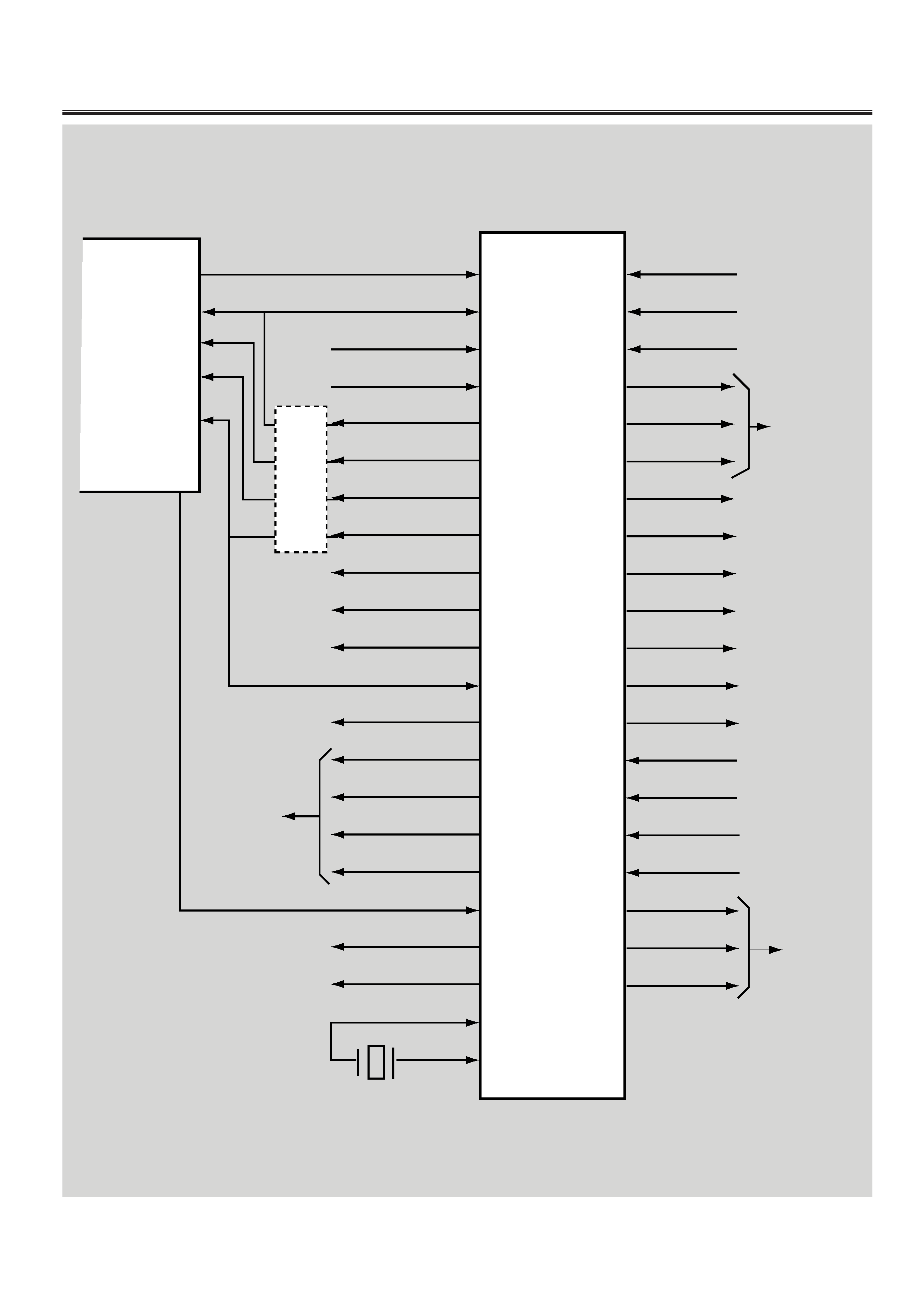
PIN CONFIGURATION OF SYSTEM CONTROL, CPU
1
2
4
5
8
9
10
11
13
14
15
16
17
19
20
21
22
23
25
26
30
31
60
63
62
61
60
59
57
56
55
53
52
46
45
44
43
42
41
36
34
33
I DENT
CHROMA ID
KEY IN
RC SIGNAL
COLOUR
BRIGHTNESS
CONTRAST
SHARPNESS
SCLK
DATA
I2C BUS SW.
SYNC ID
PAL/NTSC
THRESH HOLD
SQ
CLK
SI
AFT
I2C SCL
I2C SDA
OSC
OSC
Vcc +5V
H-SYNC
V-SYNC
OSD RED
OSD GREEN
OSD BLUE
OSD BLANKING
POWER ON/OFF
LED DRIVE
AV1 SW
AV2 SW
SOUND MUTE
LINE MUTE
SC1 FUNCTION
SC2 FUNCTION
POWER FAILURE DET.
IGNORE
TITLE IN
PITTARI
NORMAL
IC801
M37207MB-
TO SUB VIDEO
BOARD
TO Y/C SEPARATION
BOARD
D/A
CONVERTER
CIRCUITS
IDENT 4
COLOUR 26
BRIGHT 17
CONTRAST 25
SHARPNESS 14
AFT 44
IC101
TDA8361
FBP
SANDCASTLE PLS
TO
Q203,
Q204,
Q205
TO IC201-
PIN21
TO IC1001
PINS 6, 12
FROM
SCART1, 2
TO
DEFLECTION
BOARD
SYSTEM CONTROL
-4-
F2JE
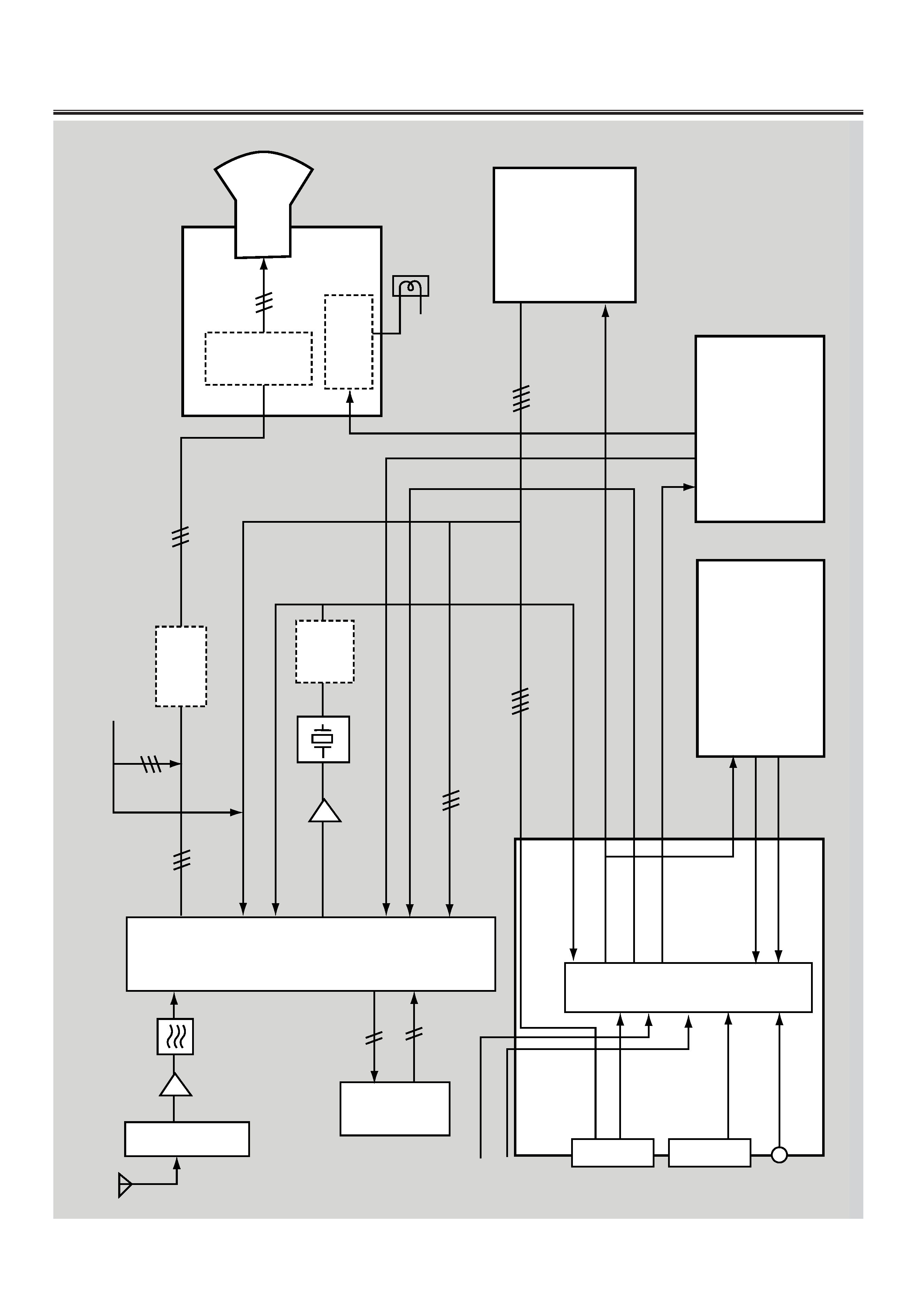
A101
TUNER
PACK
Q101
X101
SAW
IC101
TDA8361
<IF/VIDEO/CHROMA>
IC270
TDA4661
<1H
DELAY>
Q122
SIF
TRAP
Q135
Q132
Q134
EQUALISER
AV1
AV2
AV3
VIDEO-IN
VIDEO-IN
VIDEO-IN
R/G/B/BLK-IN
IC1001
TA8747N
<AV
SELECTOR>
AV1
AV2
FROM
CPU
BACK
BOARD
3L
Y/C
SEPARATION
BOARD
SUB
VIDEO
BOARD
TELETEXT
BOARD
CRT
BOARD
TV-IN
VIDEO-IN
Y-OUT
C-OUT
MONITOR-OUT
Y-OUT
C-OUT
R/G/B/BLK-OUT
R/G/B-IN
Y-IN
C-IN
BLK-IN
VIDEO-IN(INTERNAL)
VIDEO-OUT
R/G/B-OUT
R/G/B/BLK
FOR
OSD
FROM
CPU
Q203
Q204
Q205
R/G/B
BUFFER
R/G/B
R-Y/B-Y-OUT
R-Y/B-Y-IN
CRT
Q2761
Q2772
Q2782
VIDEO-OUT
45
46
30
31
28
29
16
14
11
12
22
23
24
16
15
7
13
21
20
19
18
1
35
28
33
31
25
23
13
7
1
6
12
VIDEO-IN
VM-OUT
Y-OUT
Velocity Control
circuit
BLOCK
DIAGRAM
<VIDEO
SIGNAL
PROCESSING>
CHASSIS BLOCK DIAGRAMS
-5-
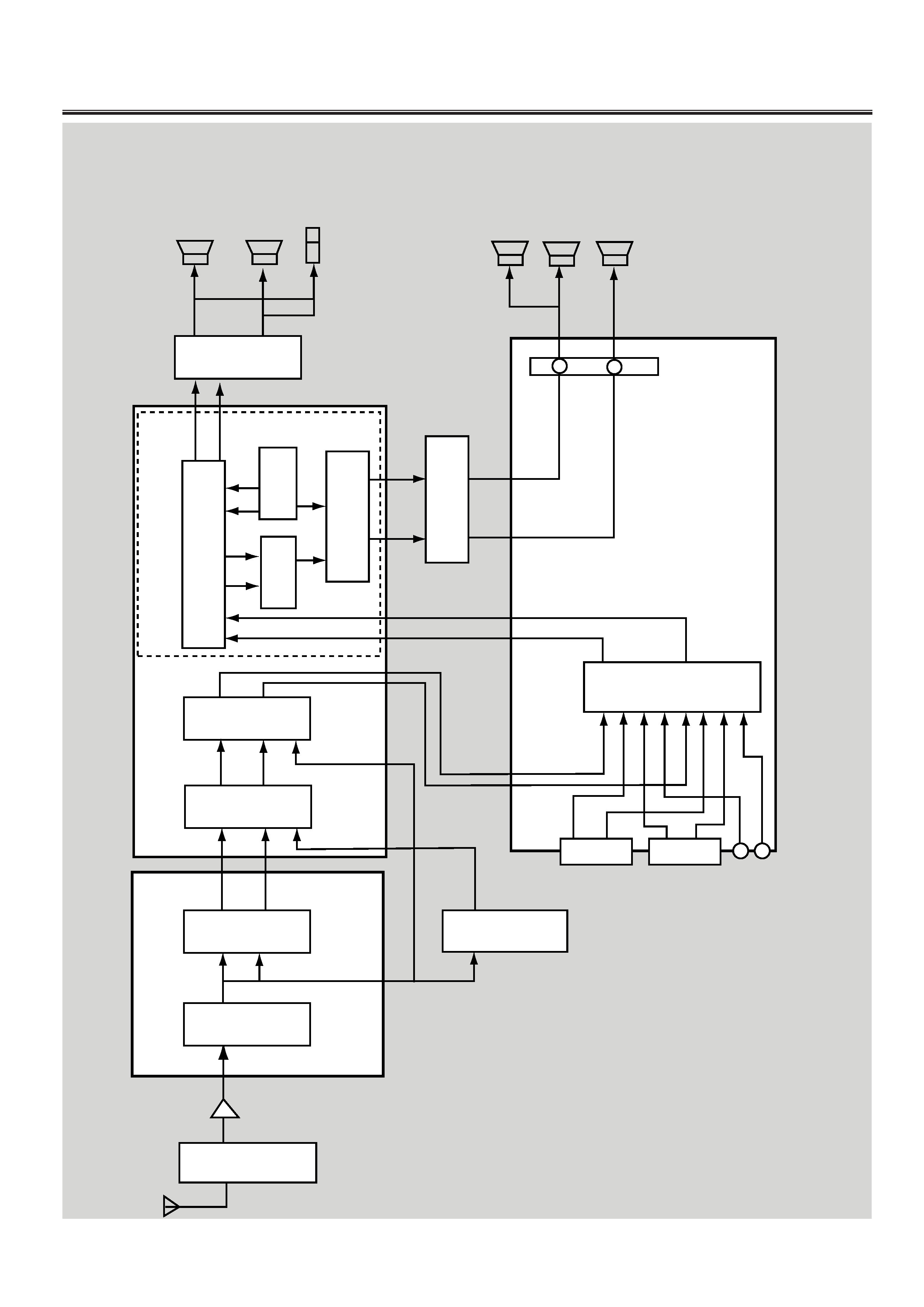
F2JE
A101
TUNER
PACK
Q101
IC3801
SIF
<TDA2545A>
IC3811
A2
STEREO
<TDA9821>
IC101
IF/VIDEO/CHROMA
<TDA8361>
IC3401
<TDA9840>
IC3451
NICAM
<SAA7283>
IC3121
<TDA9860>
IC3201
<TDA9860>
IC051
AUDIO
OUTPUT
FOR
CENTRE/REAR
<TA8216H>
IC001
AUDIO
OUTPUT
FOR
FRONT
<TA8200AH>
FRONT
L
SPEAKER
FRONT
R
SPEAKER
CENTRE
SPEAKER
SURROUND
SPEAKERS
EXT.
SP
TERMINAL
IC1001
AV
SELECTOR
<TA8747N>
BLOCK
DIAGRAM
<
AUDIO
SIGNAL
PROCESSING>
SIF
BOARD
BACK
BOARD
NICAM
&
DOLBY
BOARD
1
16
12
1
15
8
7
AF1
AF2
6
1
7
8
9
14
13
L
R
16
7
29
15
8
L
R
NICAM
MONO.
SIF
MAIN
SUB
AV1
AV2
AV3
TV-L
TV-R
AV1-L
AV2-L
AV3-L
AV1-R
AV2-R
AV3-R
36
2
8
14
34
4
10
16
27
26
35
L
R
18
15
L
R
2
4
12
7
18
15
4
2
7
12
SURROUND
CENTRE
SURROUND
CENTRE
HEADPHONES
10
23
9
24
10
9
34
13
10
15
14
23
IC3151
<LV1011>
IC3161
LA2785>
DOLBY
CIRCUIT