ORDER NO.
PIONEER CORPORATION 4-1, Meguro 1-chome, Meguro-ku, Tokyo 153-8654, Japan
PIONEER ELECTRONICS SERVICE, INC. P.O. Box 1760, Long Beach, CA 90801-1760, U.S.A.
PIONEER EUROPE NV Haven 1087, Keetberglaan 1, 9120 Melsele, Belgium
PIONEER ELECTRONICS ASIACENTRE PTE. LTD. 253 Alexandra Road, #04-01, Singapore 159936
PIONEER CORPORATION 2001
c
Type
Model
Power Requirement
Region No.
Remarks
XV-DV88
XV-DV77
ZVYXJ
DC power supplied from other system component
2
ZUCXJ
DC power supplied from other system component
1
XV-DV88
XV-DV77
RRV2480
T ZZK JULY 2001 Printed in Japan
THIS MANUAL IS APPLICABLE TO THE FOLLOWING MODEL(S) AND TYPE(S).
DVD/CD TUNER
1. SAFETY INFORMATION ....................................... 2
2. EXPLODED VIEWS AND PARTS LIST ................. 4
3. BLOCK DIAGRAM AND SCHEMATIC DIAGRAM ... 12
4. PCB CONNECTION DIAGRAM ........................... 45
5. PCB PARTS LIST ................................................ 58
6. ADJUSTMENT ..................................................... 66
7. GENERAL INFORMATION ................................ 73
7.1 DIAGNOSIS .................................................. 73
7.1.1 SELF-DIAGNOSTIC FUNCTION OF
PICKUP DEFECTIVE ........................... 73
CONTENTS
7.1.2 TEST POINTS LOCATION ................... 74
7.1.3 TEST MODE SCREEN DISPLAY ........ 75
7.1.4 TROUBLE SHOOTING ........................ 79
7.1.5 ERROR CODE ..................................... 80
7.1.6 DISASSEMBLY .................................... 84
7.1.7 SINGLE OPERATION METHOD ......... 91
7.2 PARTS .......................................................... 92
7.2.1 IC .......................................................... 92
7.2.2 DISPLAY ............................................... 95
8. PANEL FACILITIES AND SPECIFICATIONS .... 96
PLAY/PAUSE
STANDBY/ON
6
OPEN/CLOSE
STOP
0
7
1
R
¶ This product is a system(s) component.
This product does not function properly independently ; to avoid malfunctions, be
sure to connect it to the prescribed system component(s), otherwise damage may
result.
¶ Please connect it to the POWERED SUBWOOFER S-DV88SW or S-DV77SW, for
adjustment and operation inspection.
Component
Model
Service manual
Remarks
DVD/CD TUNER
XV-DV88
XV-DV77
RRV2480
This manual.
SPEAKER SYSTEM
S-DV77
RRV2473
SATELLITE SPEAKER
S-DV88ST
S-DV77ST
RRV2486, RRV2473
POWERED SUBWOOFER
S-DV88SW
S-DV77SW
RRV2474, RRV2473
MINIDISC RECORDER
MJ-L11
RRV2472
System option
STEREO CASSETTE DECK
CT-L11
RRV2471
System option
2
XV-DV88, XV-DV77
1. SAFETY INFORMATION
This service manual is intended for qualified service technicians ; it is not meant for the casual do-it-
yourselfer. Qualified technicians have the necessary test equipment and tools, and have been trained
to properly and safely repair complex products such as those covered by this manual.
Improperly performed repairs can adversely affect the safety and reliability of the product and may
void the warranty. If you are not qualified to perform the repair of this product properly and safely, you
should not risk trying to do so and refer the repair to a qualified service technician.
WARNING
This product contains lead in solder and certain electrical parts contain chemicals which are known to the state of California to cause
cancer, birth defects or other reproductive harm.
Health & Safety Code Section 25249.6 Proposition 65
NOTICE
(FOR CANADIAN MODEL ONLY)
Fuse symbols
(fast operating fuse) and/or
(slow operating fuse) on PCB indicate that replacement parts must
be of identical designation.
REMARQUE
(POUR MODÈLE CANADIEN SEULEMENT)
Les symboles de fusible
(fusible de type rapide) et/ou
(fusible de type lent) sur CCI indiquent que les pièces
de remplacement doivent avoir la même désignation.
ANY MEASUREMENTS NOT WITHIN THE LIMITS
OUTLINED ABOVE ARE INDICATIVE OF A POTENTIAL
SHOCK HAZARD AND MUST BE CORRECTED BEFORE
RETURNING THE APPLIANCE TO THE CUSTOMER.
2. PRODUCT SAFETY NOTICE
Many electrical and mechanical parts in the appliance
have special safety related characteristics. These are
often not evident from visual inspection nor the protection
afforded by them necessarily can be obtained by using
replacement components rated for voltage, wattage, etc.
Replacement parts which have these special safety
characteristics are identified in this Service Manual.
Electrical components having such features are identified
by marking with a
on the schematics and on the parts list
in this Service Manual.
The use of a substitute replacement component which does
not have the same safety characteristics as the PIONEER
recommended replacement one, shown in the parts list in
this Service Manual, may create shock, fire, or other hazards.
Product Safety is continuously under review and new
instructions are issued from time to time. For the latest
information, always consult the current PIONEER Service
Manual. A subscription to, or additional copies of, PIONEER
Service Manual may be obtained at a nominal charge from
PIONEER.
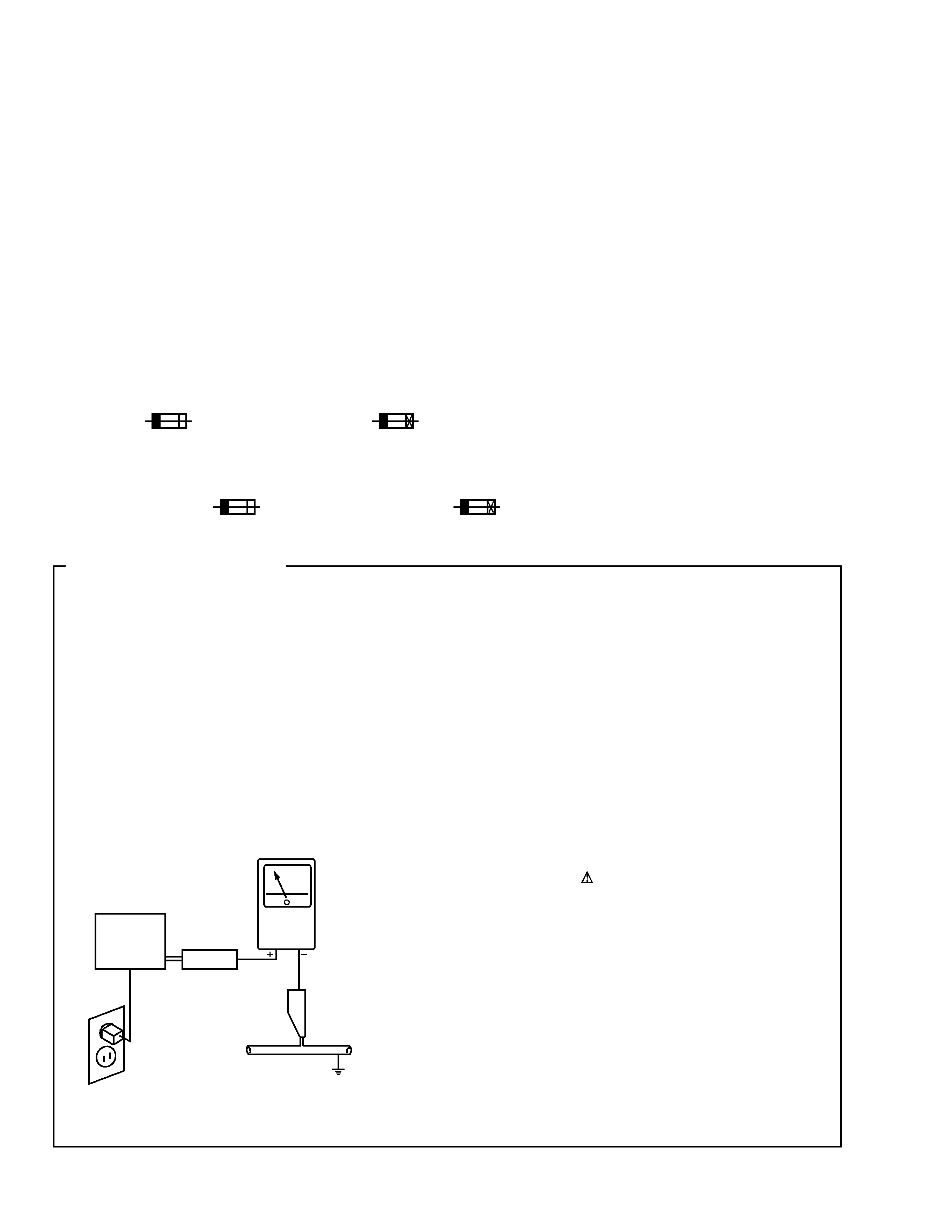
1. SAFETY PRECAUTIONS
The following check should be performed for the
continued protection of the customer and service
technician.
LEAKAGE CURRENT CHECK
Measure leakage current to a known earth ground (water
pipe, conduit, etc.) by connecting a leakage current tester
such as Simpson Model 229-2 or equivalent between the
earth ground and all exposed metal parts of the appliance
(input/output terminals, screwheads, metal overlays, control
shaft, etc.). Plug the AC line cord of the appliance directly
into a 120V AC 60Hz outlet and turn the AC power switch
on. Any current measured must not exceed 0.5mA.
(FOR USA MODEL ONLY)
Leakage
current
tester
Reading should
not be above
0.5mA
Device
under
test
Test all
exposed metal
surfaces
Also test with
plug reversed
(Using AC adapter
plug as required)
Earth
ground
AC Leakage Test
3
XV-DV88, XV-DV77
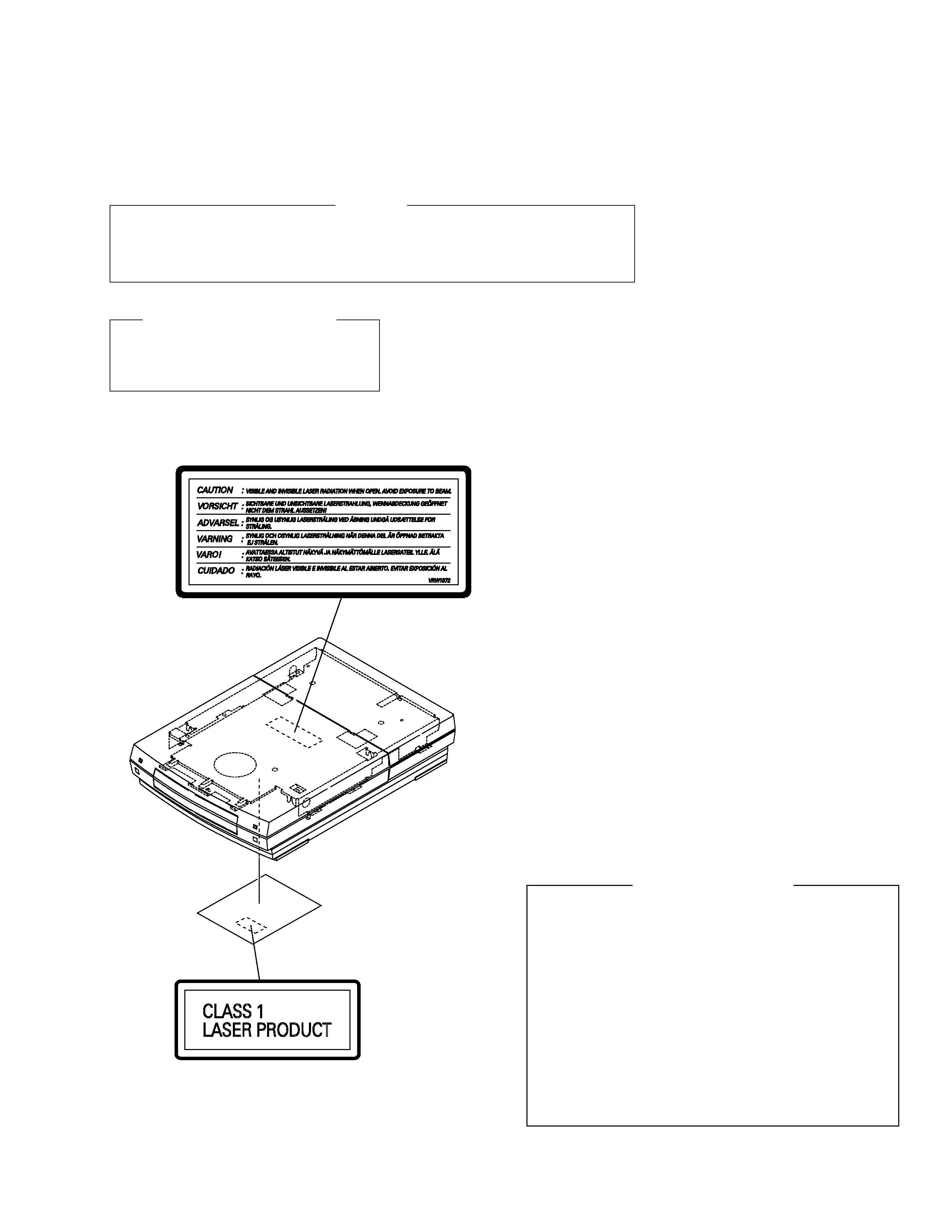
Name Lavel
LABEL CHECK (ZVYXJ TYPE ONLY)
WARNING !
THE AEL (ACCESSIBLE EMISSION LEVEL) OF THE LASER POWER OUTPUT IS LESS THAN CLASS 1
BUT THE LASER COMPONENT IS CAPABLE OF EMITTING RADIATION EXCEEDING THE LIMIT FOR
CLASS 1.
A SPECIALLY INSTRUCTED PERSON SHOULD DO SERVICING OPERATION OF THE APPARATUS.
Additional Laser Caution
1. Loading-status detection switch (S101 on the LOAB assy) are detected
by the microprocessor (IC601 in the DVDM assy).
· To permit the laser diode to oscillate, it is required to set the loading-
status detection switch for the clamp position (the center terminal of S101
is shorted to +3V).
When the voltage of IC101-pin 20 is +3V and IC601 (microprocessor) -
pin 83 is +3V, 650nm laser diode for DVD oscillates in the DVDM Assy.
When the voltage of IC101-pin 20 is +3V and IC601 (microprocessor) -
pin 83 is 0V (GND), 780nm laser diode for CD oscillates in the DVDM
Assy.
In the test mode
, the laser diode oscillates when microprocessor detects
a PLAY signal, or when the PLAY key is pressed (KEYL assy), with the
above requirements satisfied.
2. When the cover is open, close viewing through the objective lens with
the naked eye will cause exposure to the laser beam.
: See page 73.
LASER DIODE CHARACTERISTICS
FOR DVD : MAXIMUM OUTPUT POWER : 5 mW
WAVELENGTH : 650 nm
FOR CD :
MAXIMUM OUTPUT POWER : 5 mW
WAVELENGTH : 780 nm
4
XV-DV88, XV-DV77
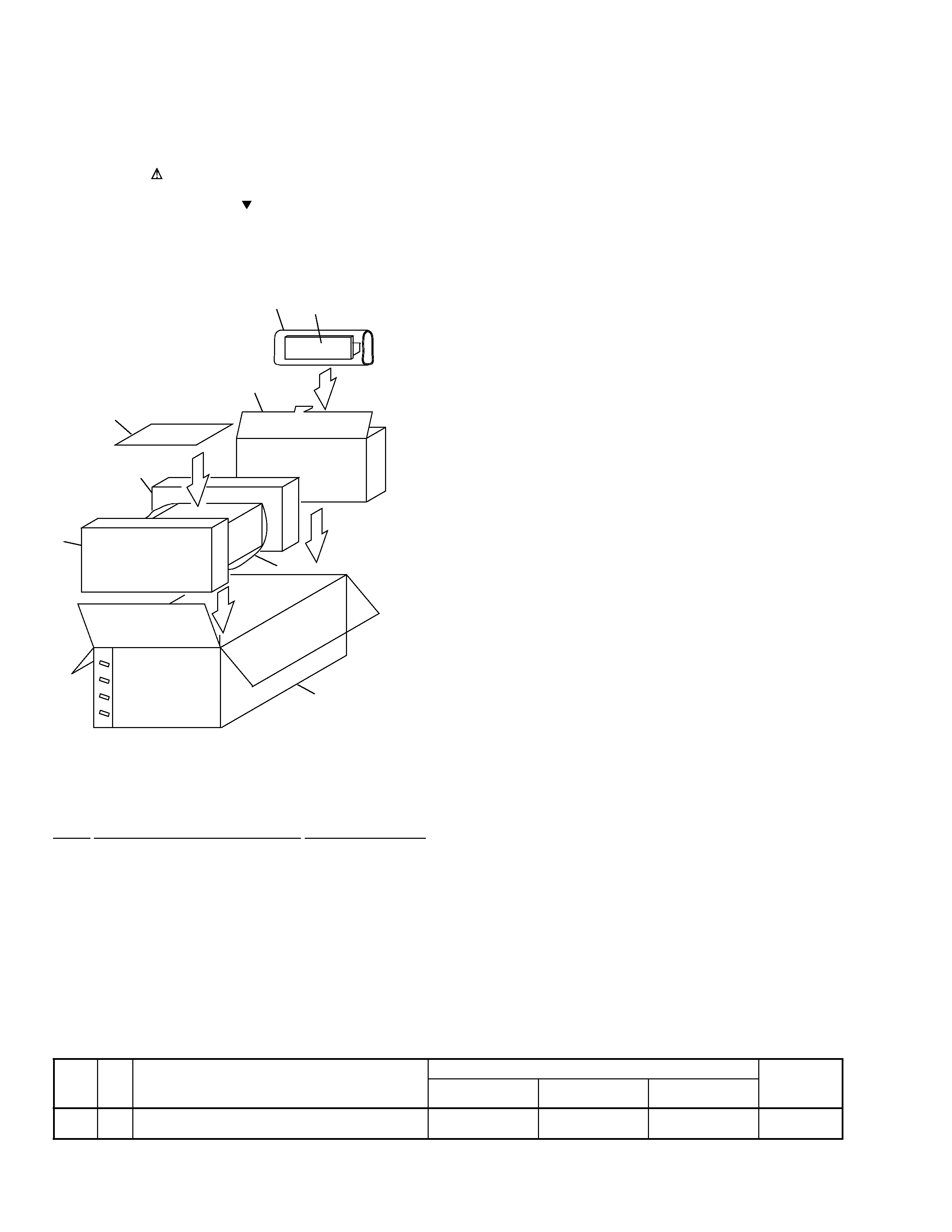
2.1 PACKING
2. EXPLODED VIEWS AND PARTS LIST
NOTES:
· Parts marked by "NSP" are generally unavailable because they are not in our Master Spare Parts List.
· The mark found on some component parts indicates the importance of the safety factor of the part.
Therefore, when replacing, be sure to use parts of identical designation.
· Screws adjacent to mark on the product are used for disassembly.
(1) PACKING PARTS LIST
Mark No.
Description
Part No.
(2) CONTRAST TABLE
XV-DV77/ZVYXJ, ZUCXJ and XV-DV88/ZVYXJ are constructed the same except for the following :
Part No.
Mark No.
Symbol and Description
XV-DV88
XV-DV77
XV-DV77
Remarks
/ZVYXJ
/ZVYXJ
/ZUCXJ
5
Packing Case
AHD8022
AHD7987
AHD7994
NSP
8
Warranty Card
ARY7022
ARY7022
ARY7045
1
DISPLAY UNIT
AXX7107
2
Front Pad
AHA7340
3
Rear Pad
AHA7341
4
Spacer NS2001
AHB7056
5
Packing Case
See Contrast table (2)
6
Packing Sheet
AHG7073
7
Seat
Z23-007
NSP
8
Warranty Card
See Contrast table (2)
6
1
3
4
5
8
7
2
Refer to
"2.2 DISPLAY UNIT".
FRONT
5
XV-DV88, XV-DV77
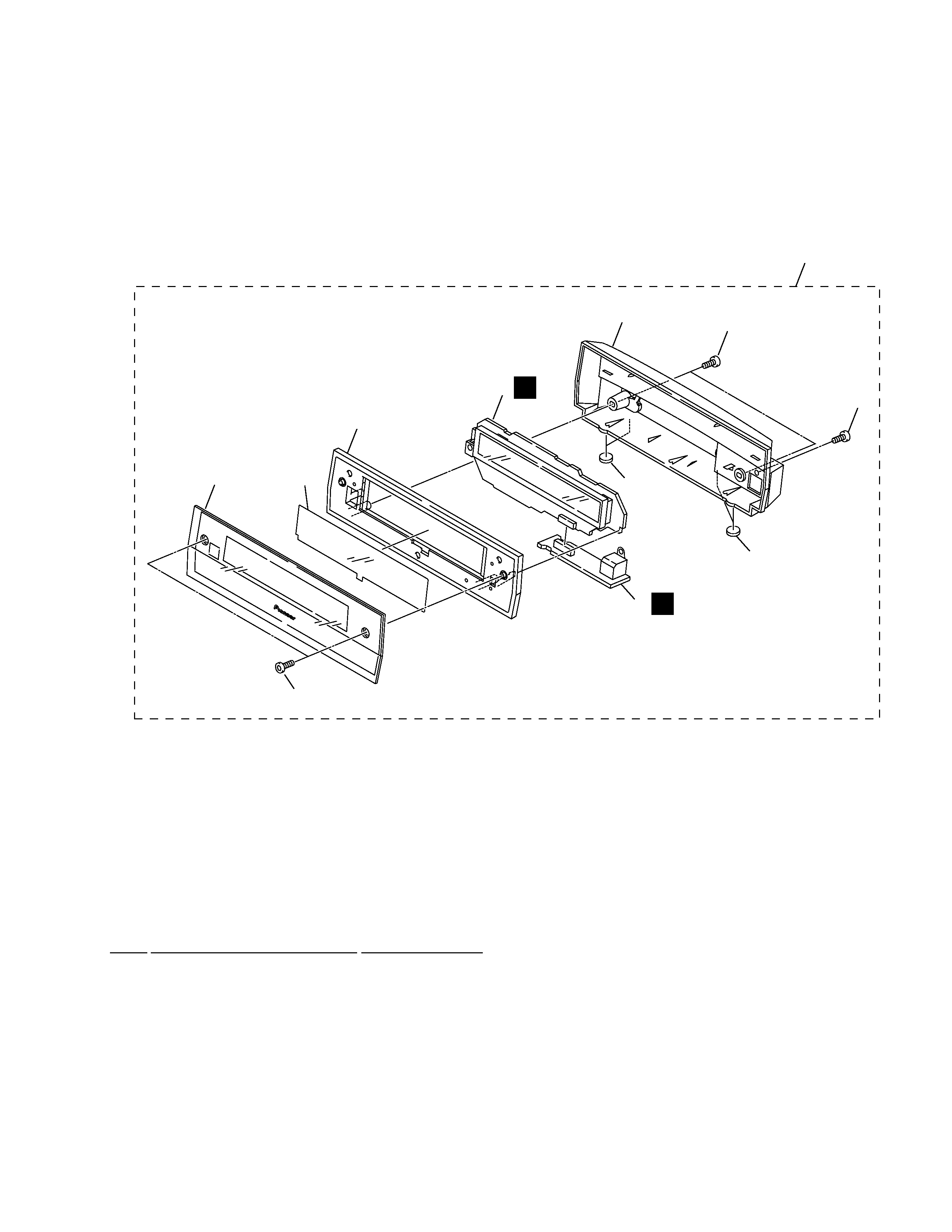
2.2 DISPLAY UNIT
Mark No.
Description
Part No.
1
FLDP ASSY
AWU7854
2
CNB ASSY
AWU7855
3
Leg
AEB7090
4
Window
AAK7889
5
Deco Screw
ABA7072
6
FL Filter
AEC7195
7
Display Panel
AMB7750
8
Display Cover
AMC7048
9
Screw
BPZ30P080FZK
10
Screw
PSC30P080FNI
11
DISPLAY UNIT
AXX7107
· DISPLAY UNIT PARTS LIST
P
1
7
4
8
6
9
10
11
O
2
5
3
3