ORDER NO.
PIONEER CORPORATION 4-1, Meguro 1-chome, Meguro-ku, Tokyo 153-8654, Japan
PIONEER ELECTRONICS (USA) INC. P.O. Box 1760, Long Beach, CA 90801-1760, U.S.A.
PIONEER EUROPE NV Haven 1087, Keetberglaan 1, 9120 Melsele, Belgium
PIONEER ELECTRONICS ASIACENTRE PTE. LTD. 253 Alexandra Road, #04-01, Singapore 159936
PIONEER CORPORATION 2004
PHONES
6 DVD/CD
0 OPEN/CLOSE
FM/AM
VOL.
ñ DOWN
UP +
7
STANDBY/ON
XV-DV525
RRV2906
DVD/CD RECEIVER
XV-DV525
XV-DV424
XV-DV323 (DCS-323)
THIS MANUAL IS APPLICABLE TO THE FOLLOWING MODEL(S) AND TYPE(S).
XV-DV323 is a system(s) component.
Model
Type
Power Requirement
Regional restriction
codes (Region No.)
Remarks
XV-DV525
MYXJ
AC220-230V
2
XV-DV525
NVXJ
AC230V
2
XV-DV424
MYXJ
AC220-230V
2
XV-DV424
NVXJ
AC230V
2
XV-DV323
MYXJ
AC220-230V
2
XV-DV323
NVXJ
AC230V
2
Component
System
Service Manual
Remarks
5.1CH SURROUND SYSTEM
DCS-323
RRV2927
DVD/CD RECEIVER
XV-DV323
RRV2906
This manual.
SPEAKER SYSTEM
S-DV323
RRV2899
For details, refer to "Important symbols for good services".
T-ZZK MAR. 2004 printed in Japan
XV-DV525
2
1234
123
4
C
D
F
A
B
E
SAFETY INFORMATION
This service manual is intended for qualified service technicians ; it is not meant for the casual do-
it-yourselfer. Qualified technicians have the necessary test equipment and tools, and have been
trained to properly and safely repair complex products such as those covered by this
manual.Improperly performed repairs can adversely affect the safety and reliability of the product
and may void the warranty. If you are not qualified to perform the repair of this product properly and
safely, you should not risk trying to do so and refer the repair to a qualified service technician.
WARNING !
THE AEL (ACCESSIBLE EMISSION LEVEL) OF THE LASER POWER OUTPUT IS LESS THAN CLASS 1
BUT THE LASER COMPONENT IS CAPABLE OF EMITTING RADIATION EXCEEDING THE LIMIT FOR
CLASS 1.
A SPECIALLY INSTRUCTED PERSON SHOULD DO SERVICING OPERATION OF THE APPARATUS.
LASER DIODE CHARACTERISTICS
FOR DVD : MAXIMUM OUTPUT POWER : 5 mW
WAVELENGTH : 650 nm
FOR CD :
MAXIMUM OUTPUT POWER : 7 mW
WAVELENGTH : 780 nm
Additional Laser Caution
1. Laser Interlock Mechanism
· Loading switch (S101 on the LOAB Assy) is used for interlock
mechanism of the laser.
When this switch turned ON in SW2 (CLOSE) side (OPEN signal is
0V and CLOSE signal is 3.5V), a laser becomes the status which can
completely oscillation.
Furthermore, the laser completely oscillates in the disc judgment and
disc playback.
When player is power ON state and laser diode is not completely
oscillating, 780nm laser diode is always oscillating by half power.
· Laser diode is driving with Q201 (650nm LD) and Q211 (780nm LD)
on the DVDM Assy.
Therefore, when short-circuit between the emitter and collector of these
transistors or the base voltage is supplied for transistors turn on, the
laser oscillates. (failure mode)
· In the test mode
, there is the mode that the laser oscillates except
for the disc judgment and playback. LD ON mode in the test mode
oscillates with the laser forcibly.
The interlock mechanism mentioned above becomes invalid in this
mode.
2. When the cover is open, close viewing through the objective lens with
the naked eye will cause exposure to the laser beam.
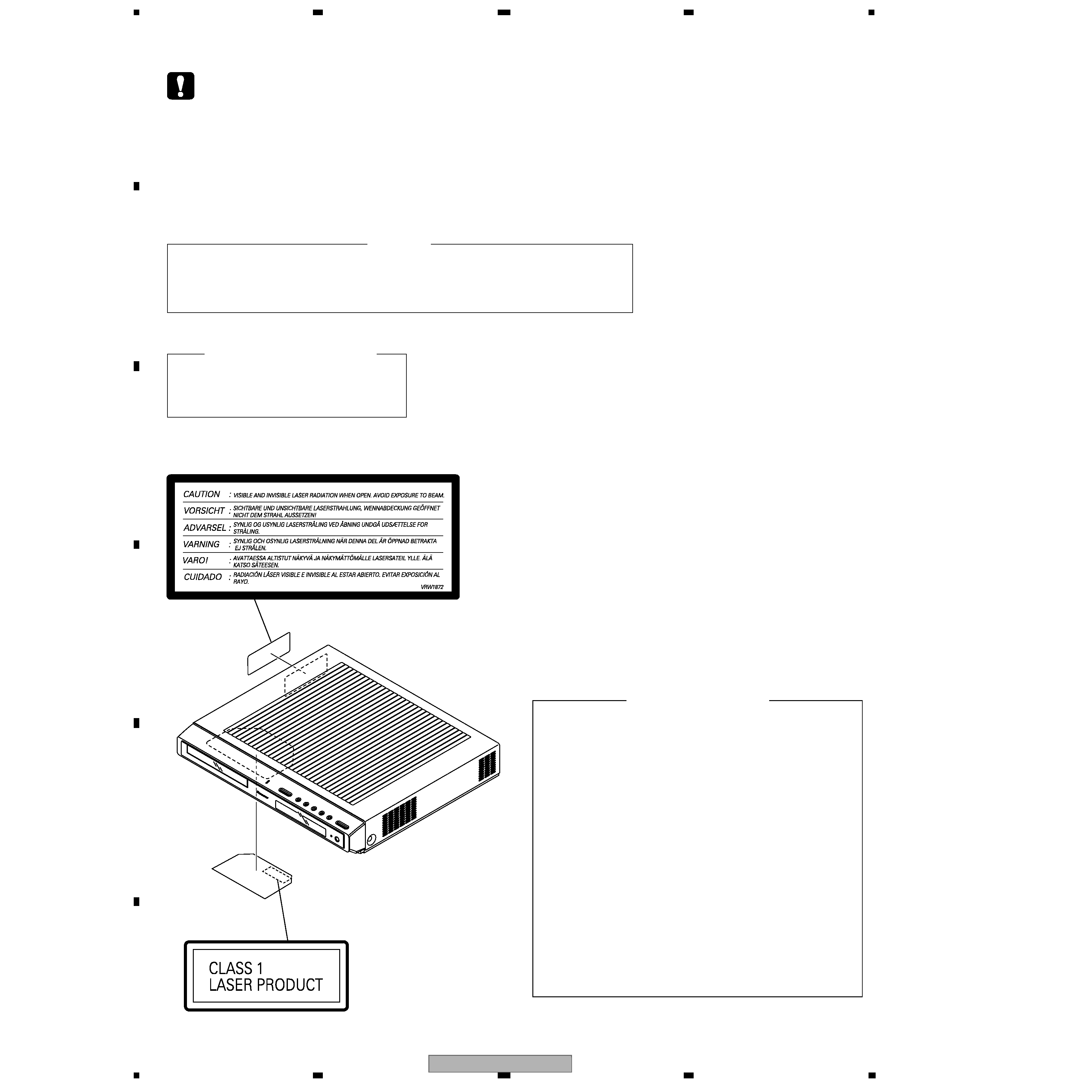
LABEL CHECK
VRW1872
Name Label
: Refer to page 82.
XV-DV525
3
5
678
56
7
8
C
D
F
A
B
E
[ Important symbols for good services ]
In this manual, the symbols shown-below indicate that adjustments, settings or cleaning should be made securely.
When you find the procedures bearing any of the symbols, be sure to fulfill them:
2. Adjustments
To keep the original performances of the product, optimum adjustments or specification confirmation is indispensable.
In accordance with the procedures or instructions described in this manual, adjustments should be performed.
3. Cleaning
For optical pickups, tape-deck heads, lenses and mirrors used in projection monitors, and other parts requiring cleaning,
proper cleaning should be performed to restore their performances.
5. Lubricants, glues, and replacement parts
Appropriately applying grease or glue can maintain the product performances. But improper lubrication or applying
glue may lead to failures or troubles in the product. By following the instructions in this manual, be sure to apply the
prescribed grease or glue to proper portions by the appropriate amount.For replacement parts or tools, the prescribed
ones should be used.
4. Shipping mode and shipping screws
To protect the product from damages or failures that may be caused during transit, the shipping mode should be set or
the shipping screws should be installed before shipping out in accordance with this manual, if necessary.
1. Product safety
You should conform to the regulations governing the product (safety, radio and noise, and other regulations), and
should keep the safety during servicing by following the safety instructions described in this manual.
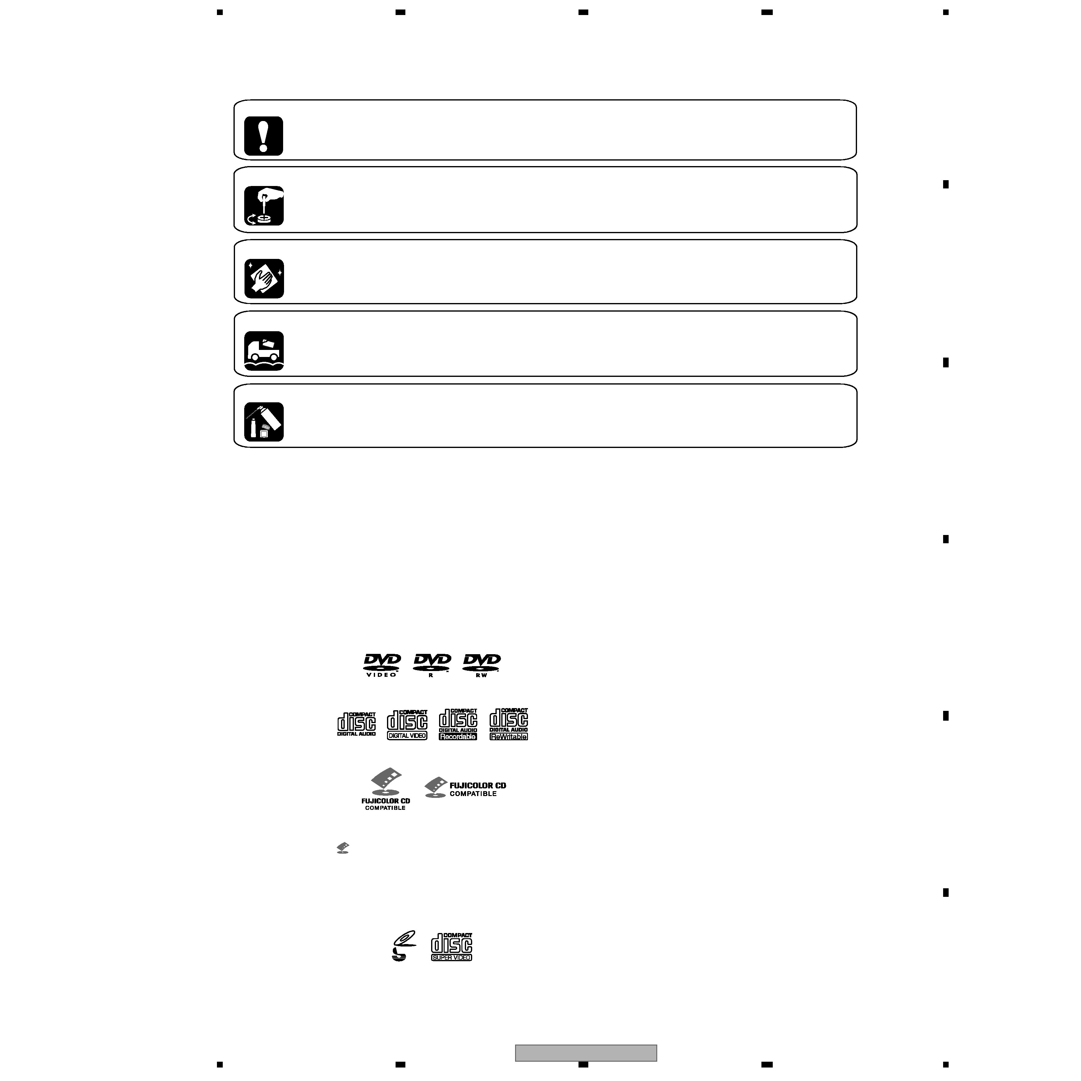
Disc / content format playback
compatibility
This player is compatible with a wide range of
disc types (media) and formats. Playable discs
will generally feature one of the following logos
on the disc and/or disc packaging. Note
however that some disc types, such as
recordable CD and DVD, may be in an
unplayable formatósee below for further
compatibility information.
·
is a trademark of Fuji Photo Film Co. Ltd.
·
Also compatible with KODAK Picture CD
This player supports the IECís Super VCD stan-
dard for superior picture quality, dual
soundtracks, and widescreen support.
DVD-Video
DVD-R
DVD-RW
Video CD
Fujicolor CD
Audio CD
CD-R
CD-RW
VIDEO
CD
Super Video CD (Super VCD)

XV-DV525
4
1234
123
4
C
D
F
A
B
E
CONTENTS
SAFETY INFORMATION ..................................................................................................................................... 2
1. SPECIFICATIONS ............................................................................................................................................ 5
2. EXPLODED VIEWS AND PARTS LIST ............................................................................................................ 6
2.1 PACKING ................................................................................................................................................... 6
2.2 EXTERIOR SECTION................................................................................................................................ 8
2.3 FRONT PANEL SECTION ....................................................................................................................... 10
2.4 01 LOADER ASSY................................................................................................................................... 12
2.5 TRAVERSE MECHA ASSY-S .................................................................................................................. 14
3. BLOCK DIAGRAM AND SCHEMATIC DIAGRAM ..........................................................................................16
3.1 BLOCK DIAGRAM ................................................................................................................................... 16
3.2 LOAB ASSY and OVERALL WIRING DIAGRAM..................................................................................... 18
3.3 DVDM ASSY(1/3)..................................................................................................................................... 20
3.4 DVDM ASSY(2/3)..................................................................................................................................... 22
3.5 DVDM ASSY(3/3)..................................................................................................................................... 24
3.6 DSP ASSY (1/2)....................................................................................................................................... 26
3.7 DSP ASSY (2/2)....................................................................................................................................... 28
3.8 6CH AMP ASSY ...................................................................................................................................... 30
3.9 CONTROL(1/4), TRADE3 and TRADE2 ASSYS ..................................................................................... 32
3.10 CONTROL ASSY(2/4)............................................................................................................................ 34
3.11 CONTROL ASSY(3/4)............................................................................................................................ 36
3.12 CONTROL ASSY(4/4) and HP ASSYS.................................................................................................. 38
3.13 POWER ASSY(1/2)................................................................................................................................ 40
3.14 POWER ASSY(2/2) and TRADE1 ASSYS............................................................................................. 42
3.15 EURO SCART ASSY ............................................................................................................................. 44
3.16 DISPALY ASSY ...................................................................................................................................... 46
3.17 WAVEFORMS ........................................................................................................................................ 48
4. PCB CONNECTION DIAGRAM ..................................................................................................................... 49
4.1 LOAB ASSY ............................................................................................................................................. 49
4.2 DVDM ASSY ............................................................................................................................................ 50
4.3 DSP ASSY ............................................................................................................................................... 52
4.4 6CH AMP ASSY ...................................................................................................................................... 54
4.5 CONTROL ASSY ..................................................................................................................................... 56
4.6 TRADE2,TRADE3 and HP ASSYS .......................................................................................................... 60
4.7 POWER ASSY ......................................................................................................................................... 62
4.8 TRADE1, EURO SCART and DISPLAY ASSYS...................................................................................... 66
5. PCB PARTS LIST ........................................................................................................................................... 70
6. ADJUSTMENT ............................................................................................................................................... 77
6.1 ADJUSTMENT ITEMS AND LOCATION ................................................................................................. 77
6.2 JIGS AND MEASURING INSTRUMENTS ............................................................................................... 77
6.3 NECESSARY ADJUSTMENT POINTS ................................................................................................... 78
6.4 TEST MODE ............................................................................................................................................ 79
6.5 MECHANISM ADJUSTMENT .................................................................................................................. 80
7. GENERAL INFORMATION ............................................................................................................................. 82
7.1 DIAGNOSIS ............................................................................................................................................. 82
7.1.1 TEST MODE ...................................................................................................................................... 82
7.1.2 DISPLAY SPECIFICATIONS OF THE TEST MODE ......................................................................... 84
7.1.3 FUNCTIONAL SPECIFICATION OF THE SHORTCUT KEY ............................................................ 85
7.1.4 SPECIFICATION OF MODEL INFORMATION DISPLAY .................................................................. 86
7.1.5 FUNCTIONAL SPECIFICATION OF THE SERVICE MODE ............................................................. 87
7.1.6 MECHANICAL ERROR HISTORY..................................................................................................... 88
7.1.7 ID NUMBER AND DATA SETTING.................................................................................................... 93
7.1.8 METHOD FOR DIAGNOSING DEGRADATION OF THE LDS ON THE PICKUP ASSY .................. 96
7.1.9 TROUBLE SHOOTING ...................................................................................................................... 97
7.1.10 DSP TROUBLE SHOOTING ......................................................................................................... 100
7.1.11 DISASSEMBLY.............................................................................................................................. 102
7.2 IC ........................................................................................................................................................... 111
7.3 EXPLANATION ...................................................................................................................................... 114
7.3.1 SEQUENCE AFTER POWER ON ................................................................................................... 114
7.3.2 PROTECTION CIRCUIT.................................................................................................................. 115
7.4 CLEANING............................................................................................................................................. 119
8. PANEL FACILITIES ...................................................................................................................................... 120
XV-DV525
5
5
678
56
7
8
C
D
F
A
B
E
1. SPECIFICATIONS
Amplifier section
Continuous Power Output (RMS):
Argentina and Brazil models:
Front, Center, Surround . . . 90 W per channel
(1 kHz, 10 % T.H.D., 6
)
Subwoofer . . .90 W (100 Hz, 10 % T.H.D., 6 )
All other models:
Front, Center, Surround . . 100 W per channel
(1 kHz, 10 % T.H.D., 6
)
Subwoofer . .100 W (100 Hz, 10 % T.H.D., 6 )
Continuous Power Output:
Argentina and Brazil models:
Front, Center, Surround . . . 68 W per channel
(1 kHz, 1 % T.H.D., 6
)
Subwoofer . . . .68 W (100 Hz, 1 % T.H.D., 6 )
All other models:
Front, Center, Surround . . . 75 W per channel
(1 kHz, 1 % T.H.D., 6
)
Subwoofer . . . .75 W (100 Hz, 1 % T.H.D., 6 )
Disc section
Digital audio
characteristics . . . . . . . . . DVD fs: 96 kHz, 24-bit
Type . . . . . . . DVD system, video CD system and
compact disc digital audio system
Total harmonic distortion. . . . . . . . . . . . . 0.004%
Frequency
response . . . .4 Hz to 44 kHz (96kHz sampling) /
4 Hz to 22 kHz (48kHz sampling)
Wow and Flutter . . . . . . . .Limit of measurement
(
±0.001 % W.PEAK) or less (JEITA)
FM tuner section
Frequency range. . . . . . . . . . . . . 87.5 108 MHz
Antenna . . . . . . . . . . . . . . . . . . 75
, unbalanced
AM tuner section
Frequency range
With 9kHz step . . . . . . . .531 kHz to 1,602 kHz
With 10kHz step (
Not applicable to
the European model). . 530 kHz to 1,700 kHz
Antenna . . . . . . . . . . . . . . . . . . . . . Loop antenna
Miscellaneous
Power requirements
European/Singapore/South African
models . . . . . . . . . . . . AC 220-230 V, 50/60 Hz
U.K. model . . . . . . . . . . . . .AC 230 V, 50/60 Hz
Australian/New Zealand/Malaysian
models . . . . . . . . . . . . . . . AC 240 V, 50/60 Hz
Argentina/Brazil models . . AC 220 V, 50/60 Hz
Hong Kong model . . . . . .AC 220-230 V, 50 Hz
Taiwan model. . . . . . . . . .AC 110-120 V, 60 Hz
Mexican model . . . . . . . . AC 127 V, 50/60 Hz
Power consumption . . . . . . . . . . . . . . . . . . 175W
Power consumption in standby . . . . . . . . . 0.5 W
Dimensions . . . . 420 (W) x 70 (H) x 396 (D) mm
Weight
Manufactured under license from Dolby
Laboratories. "Dolby", "Pro Logic" and the double-D
symbol are trademarks of Dolby Laboratories.
"DTS" and "DTS Digital Surround" are registered
trademarks of Digital Theater Systems, Inc.
. . . . . . . . . . . . . . . . . . . . . . . . . . . . 7.0 kg
Accessories (DVD/CD receiver)
Remote control . . . . . . . . . . . . . . . . . . . . . . . . . 1
AA/R6 dry cell batteries. . . . . . . . . . . . . . . . . . . .2
Video cable (yellow plugs) . . . . . . . . . . . . . . . . . 1
AM loop antenna . . . . . . . . . . . . . . . . . . . . . . . . .1
FM antenna . . . . . . . . . . . . . . . . . . . . . . . . . . . . 1
Power cord . . . . . . . . . . . . . . . . . . . . . . . . . . . . . 1
Setup Guide . . . . . . . . . . . . . . . . . . . . . . . . . . . .1
Operating instructions . . . . . . . . . . . . . . . . . . . . 1
Warranty Card (
European, Australian and New
Zealand models only) . . . . . . . . . . . . . . . . . . . .1
Note
· Specifications and design subject to
possible modification without notice, due
to improvements.
ST+
TUNE+
ENTER
TUNE
MASTER
VOLUME
ST
STANDBY/ON
CD
FM/AM
OPEN CLOSE
DISPLAY
DVD
TUNER
TV
LINE
L1/L2
DVD MENU
RETURN
SOUND
TV CONTROL
CH
VOL
INPUT
OPEN
MUTE
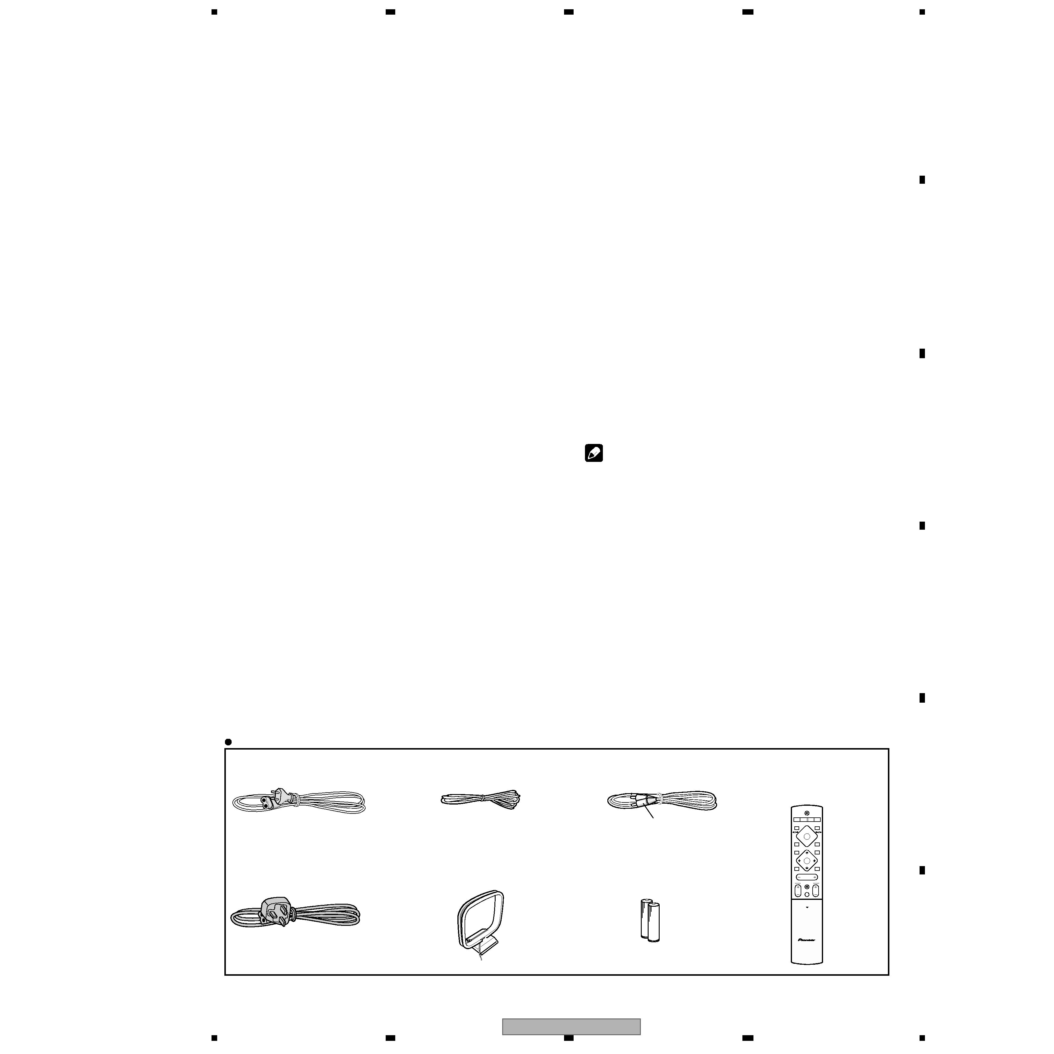
Accessories
· Power cord
(MYXJ : ADG1154)
· FM Antenna
(ADH7030)
· Power cord
(NVXJ : ADG1156)
· AM Loop Antenna
(ATB7013)
· Video Cable
(L = 1.5m)(XDE3046)
· Remote Control
(XXD3077 : XV-DV525)
(XXD3076 : XV-DV424)
(XXD3076 : XV-DV323)
· Dry Cell Batteries
(R6P, AA)
Yellow