ORDER NO.
PIONEER CORPORATION 4-1, Meguro 1-chome, Meguro-ku, Tokyo 153-8654, Japan
PIONEER ELECTRONICS SERVICE, INC. P.O. Box 1760, Long Beach, CA 90801-1760, U.S.A.
PIONEER EUROPE NV Haven 1087, Keetberglaan 1, 9120 Melsele, Belgium
PIONEER ELECTRONICS ASIACENTRE PTE. LTD. 253 Alexandra Road, #04-01, Singapore 159936
PIONEER CORPORATION 2000
c
XR-MT3
RRV2343
T IZK JULY 2000 Printed in Japan
STEREO CD RECEIVER
1. SAFETY INFORMATION ....................................... 2
2. EXPLODED VIEWS AND PARTS LIST ................. 4
3. BLOCK DIAGRAM AND SCHEMATIC DIAGRAM ... 10
4. PCB CONNECTION DIAGRAM ........................... 22
5. PCB PARTS LIST ................................................ 32
6. ADJUSTMENT ..................................................... 37
CONTENTS
7. GENERAL INFORMATION ................................ 41
7.1 DIAGNOSIS .................................................. 41
7.1.1 TROUBLE SHOOTING ........................ 41
7.1.2 DISASSEMBLY/ASSEMBLY ................ 45
7.2 PARTS .......................................................... 53
7.2.1 IC .......................................................... 53
7.2.2 DISPLAY ............................................... 55
7.3 REMOTE CONTROL UNIT .......................... 56
8. PANEL FACILITIES AND SPECIFICATIONS .... 58
Type
Model
Power Requirement
The voltage can be converted by
XR-MT3
the following method.
KUCXCN
AC120V
MYXCN
AC220-230V
NVXCN
AC230V
DBDXCN
AC110-127V/220-230V/240V
With the voltage selector
DLXCN/NC
AC110-127V/220-230V/240V
With the voltage selector
THIS MANUAL IS APPLICABLE TO THE FOLLOWING MODEL(S) AND TYPE(S).
Component
Model
Service
Remarks
manual
STEREO CD RECEIVER SYSTEM
X-MT2000
RRV2342
KUCXCN
MYXCN,NVXCN
DBDXCN
DLXCN/NC
STEREO CD RECEIVER
XR-MT3
XR-MT3
XR-MT3
XR-MT3
RRV2343
This manual.
SPEAKER SYSTEM
S-MT3W
S-MT3H
S-MT3
S-MT3-N
RRV2344
¶ System Component Table
8
XR-MT3
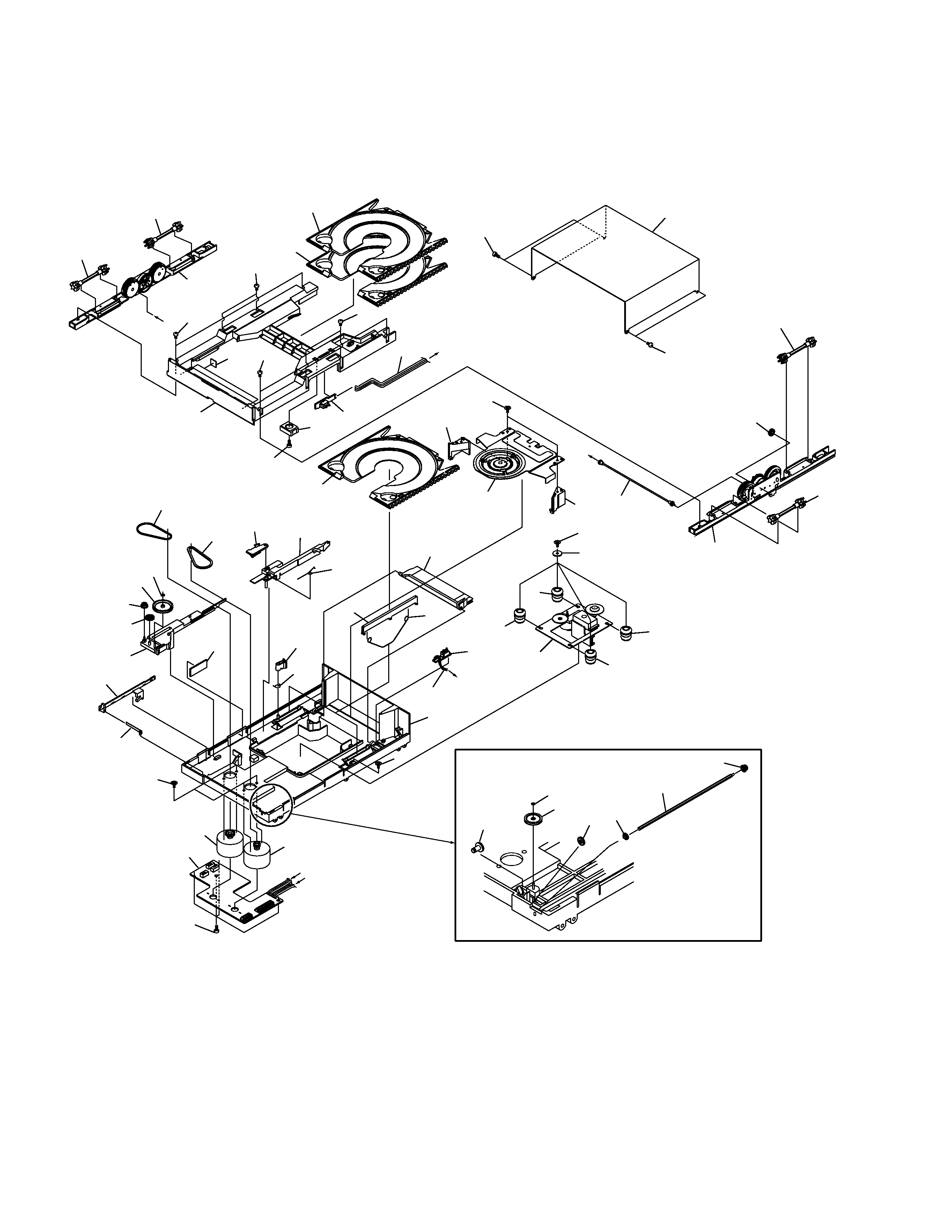
2.2 CD MECHA. SECTION
C
A
C
B
B
A
8
8
3
51
6
41
51
56
50
37
50
2
43
46
55
42
20
53
18
19
49
9
49
8
7
5
8
4
53
52
38
39
40
39
38
27
45
21
24
35
36
48
29
25
26
22
47
11
15
54
23
33
32
57
28
1
53
30
31
44
49
16
48
17
14
12
10
13
34
45
XR-MT3
Unhook
Unook
12
12
Unook
× 2
1
× 2
1
× 2
1
× 2
× 2
11
× 2
4
6
6
7
5
2
3
× 2
1
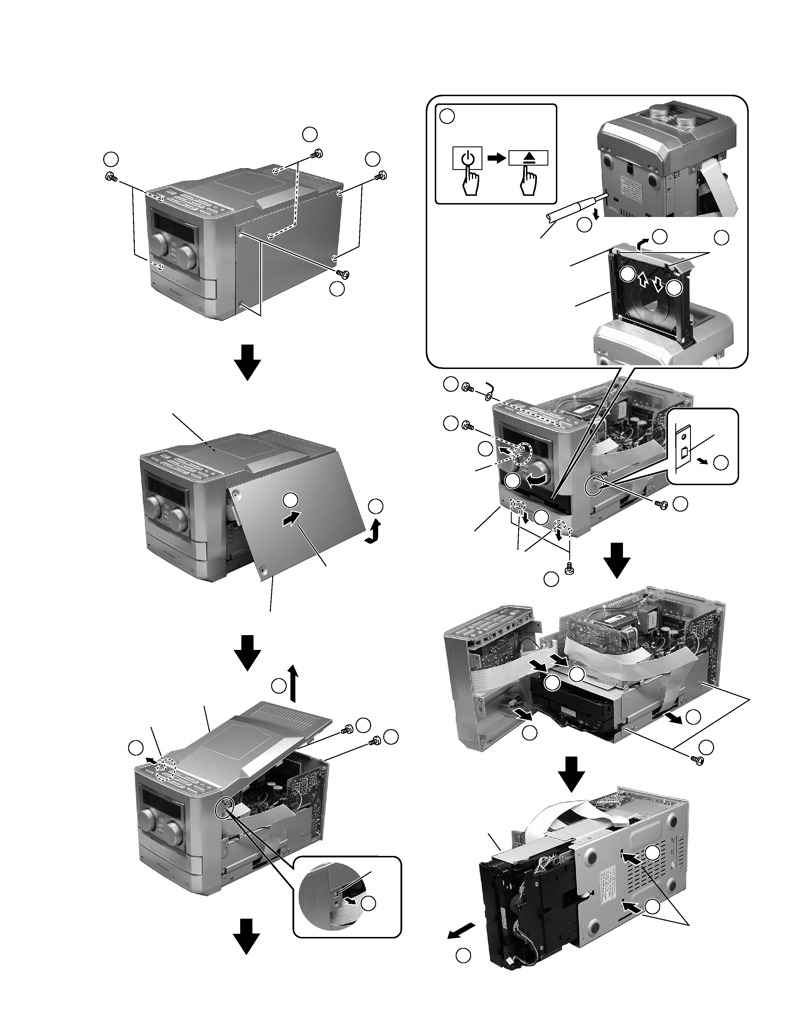
Side Panel R
Front Unit
After the slide is
done on a rear
side, Side Panel R
removes.
Side Panel L
(Remove as well as Side Panel R)
4
STANDBY/ON
or
CD
OPEN/CLOSE
Unook
Tray Panel Set
Drawer
Flat Blade Screwdriver
9
11
10
11
11
12
Unhook
5
Unhook
Top Panel
5
13
8
7.1.2 DISASSEMBLY/ASSEMBLY
(1) Main Body Section
× 2
14
15
15
15
(Remove as well as Side R)
15
16
16
17
The CD MECHA.
is drawn out while
pushing the hook.
CD MECHA.
46
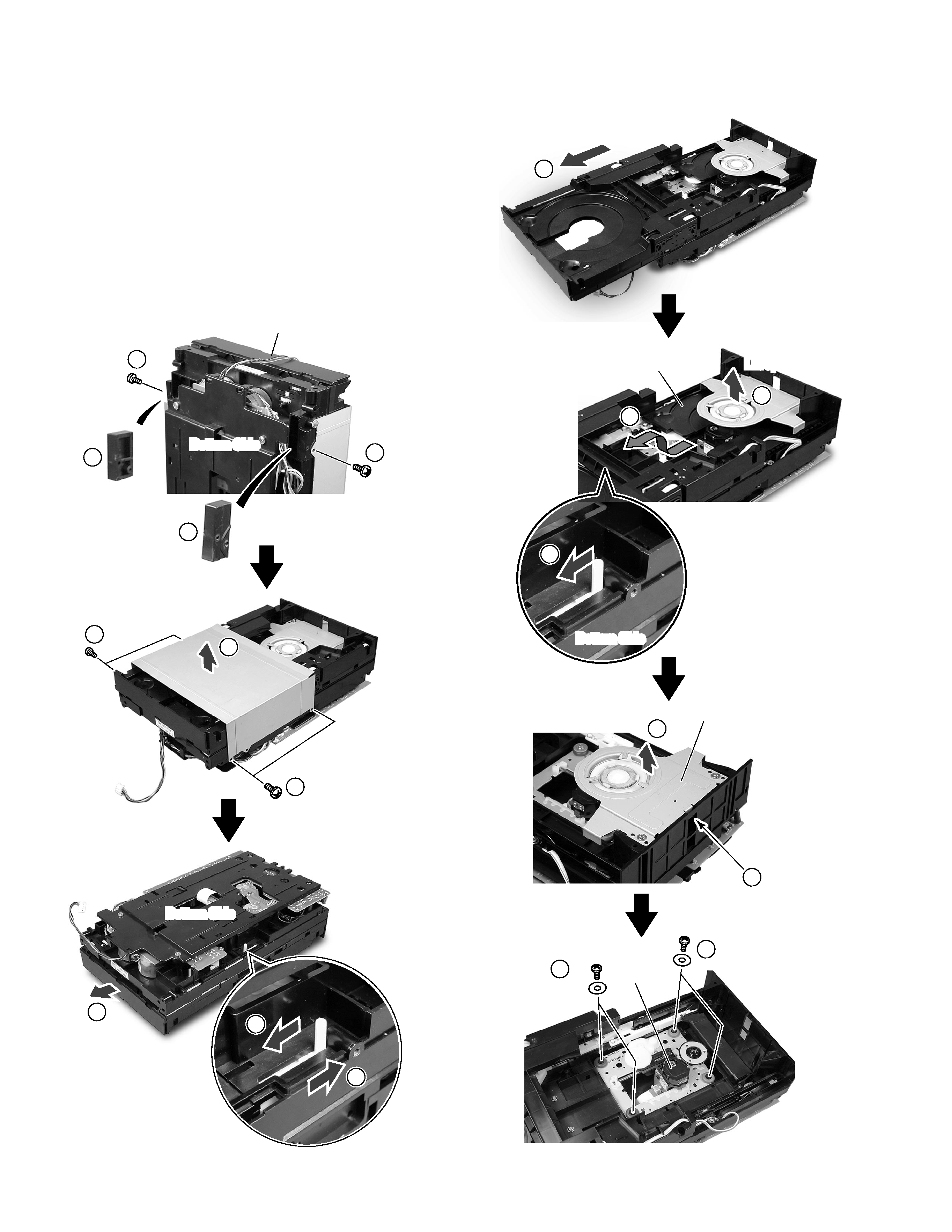
XR-MT3
(2) CD MECHA.
7 Pickup Unit
CAUTION
· If Tray Panel Set is not detached when the CD MECHA. is
repaired, the CD MECHA. cannot be removed from the main
body of the product.
When Drawer was not able not to open and shut by some
something wrong's (The power supply does not enter, etc.)
occurring, and remove Tray Panel Set, Slider 2 of the CD
MECHA. is moved from the ditch of the chassis on the bottom
side of the product with a minus driver and Drawer is drawn out.
Afterwards, please remove Front Unit after removing Tray Panel
Set .
1
2
2
3
4
3
1
CD MECHA.
Carriage 300
Ass'y Clamper S0
Bottom Side
Bottom Side
×2
×2
×2
×2
5
6
6
Bottom Side
7
8
11
12
12
9
8
Lift up
Disconnect the Hook
Pickup Unit
10
Drawer is drawn out.
Clamper is raised and
Carriage 300 is taken out.
47
XR-MT3
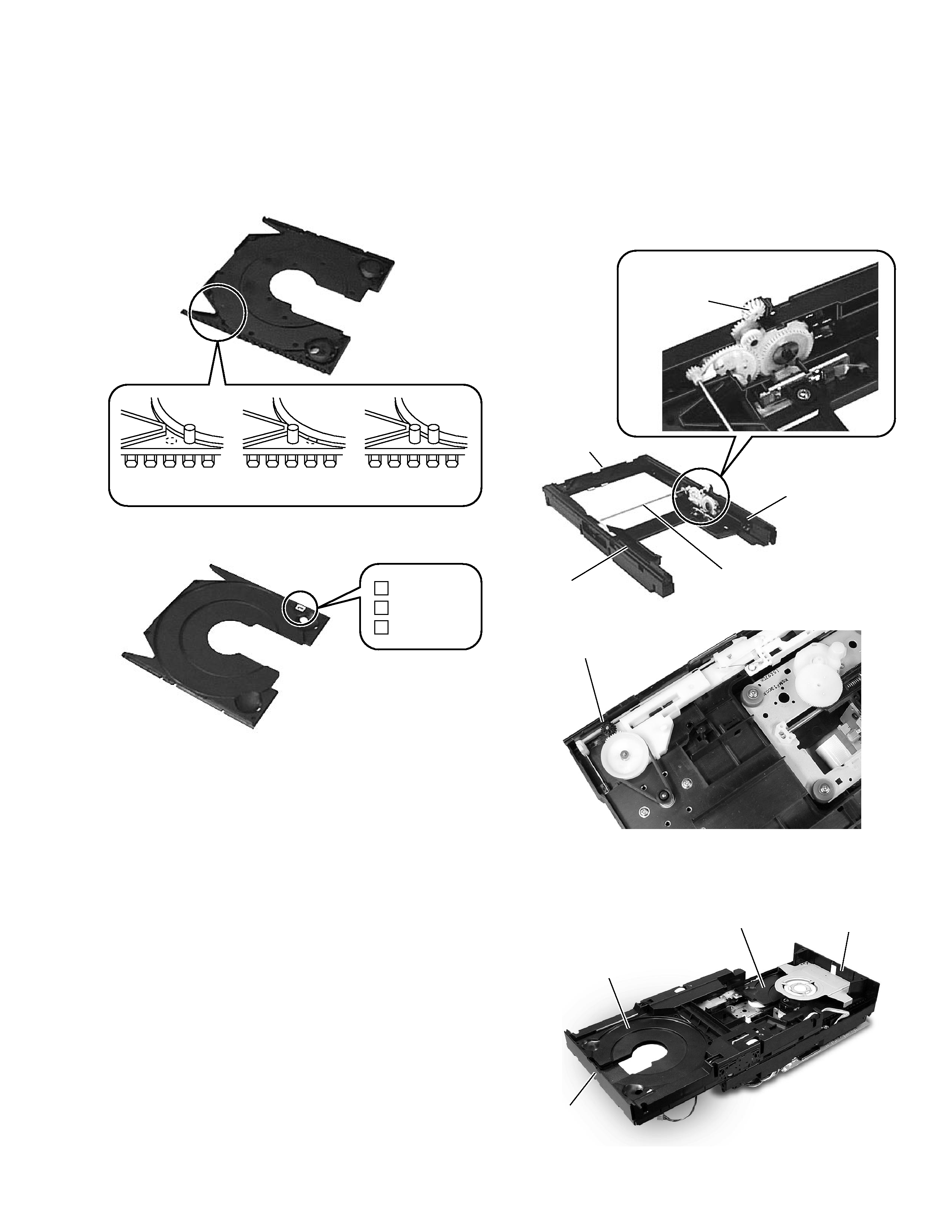
7 Caution for Disassembly/Assembly of CD MECHA.
1. As for the distinction method of Carriage100, 200, and 300,
Switch distinguishes the shape of the projection part on its back.
Please confirm the number seal pasted to the surface of
Carriage and the projection shape of the figure below when you
exchange it.
2. Please do not disassemble Assy Holder L, R and the inside of
and Drawer, and do not disassemble Assy Gear Drive which
connects Assy Holder L with R.
(The position match of each gear is necessary)
3. Please do not lose the gear (Bevel Gear 4 and Gear Idler A) not
fixed while put in the axis.
Carriage 100
Method of distinguishing the back of Carriage.
Method of distinguishing surface of Carriage.
Carriage 200
Carriage 300
Carriage 100
1
Carriage 200
2
Carriage 300
3
4. Carriage 300 is put in the Chassis side, and please put in the
Drawer side without fail in order of Carriage 100 and 200.
Bevel Gear 4
Drawer
Assy Gear Drive
Assy Holder R
Assy Holder L
Gear Idler A
Carriage 100, 200
Carriage 300
Chassis
Drawer