ORDER NO.
PIONEER CORPORATION 4-1, Meguro 1-chome, Meguro-ku, Tokyo 153-8654, Japan
PIONEER ELECTRONICS SERVICE, INC. P.O. Box 1760, Long Beach, CA 90801-1760, U.S.A.
PIONEER ELECTRONIC (EUROPE) N.V. Haven 1087, Keetberglaan 1, 9120 Melsele, Belgium
PIONEER ELECTRONICS ASIACENTRE PTE. LTD. 253 Alexandra Road, #04-01, Singapore 159936
PIONEER CORPORATION 1999
c
XC-L77
RRV2237
1. SAFETY INFORMATION ...................................... 2
2. EXPLODED VIEWS AND PARTS LIST ............... 3
3. BLOCK DIAGRAM AND SCHEMATIC DIAGRAM ... 10
4. PCB CONNECTION DIAGRAM ......................... 24
5. PCB PARTS LIST ............................................... 36
6. ADJUSTMENT .................................................... 42
CONTENTS
7. GENERAL INFORMATION ................................ 45
7.1 DISASSEMBLY ............................................ 45
7.2 PARTS .......................................................... 48
7.2.1 IC ............................................................ 48
7.2.2 DISPLAY ................................................. 51
8. PANEL FACILITIES AND SPECIFICATIONS ....... 52
T ZZK NOV. 1999 Printed in Japan
STEREO CD RECEIVER
Type
Model
Power Requirement
Remarks
XC-L77
KUXJ/CA
AC120V
THIS MANUAL IS APPLICABLE TO THE FOLLOWING MODEL(S) AND TYPE(S).
6
0
STANDBY/ON
PHONES
¶ This product is a system(s) component.
Be sure to connect it to the prescribed system component(s), otherwise damage may
result.
Component
Model
Service manual
Remarks
STEREO CD RECEIVER
XC-L77
RRV2237
This manual.
SPEAKER SYSTEM
S-L9-LRW
RRV2239
S-L9-A-LRW
RRV2239
2
XC-L77
1. SAFETY INFORMATION
This service manual is intended for qualified service technicians; it is not meant for the casual
do-it-yourselfer. Qualified technicians have the necessary test equipment and tools, and have been
trained to properly and safely repair complex products such as those covered by this manual.
Improperly performed repairs can adversely affect the safety and reliability of the product and may
void the warranty. If you are not qualified to perform the repair of this product properly and safely, you
should not risk trying to do so and refer the repair to a qualified service technician.
WARNING
This product contains lead in solder and certain electrical parts contain chemicals which are known to the state of California to
cause cancer, birth defects or other reproductive harm.
Health & Safety Cod e Section 25249.6 Proposition 65
NOTICE
(FOR CANADIAN MODEL ONLY)
Fuse symbols
(fast operating fuse)
and/or
(slow operating fuse) on PCB indicate that replacement
parts must be of identical designation.
REMARQUE
(POUR MODÈLE CANADIEN SEULEMENT)
Les symboles de fusible
(fusible de type rapide)
et/ou
(fusible de type lent) sur CCI indiquent que
les pièces de remplacement doivent avoir la même désignation.
ANY MEASUREMENTS NOT WITHIN THE
LIMITS OUTLINED ABOVE ARE INDICATIVE
OF A POTENTIAL SHOCK HAZARD AND
MUST BE CORRECTED BEFORE RETURN-
ING THE APPLIANCE TO THE CUSTOMER.
2. PRODUCT SAFETY NOTICE
Many electrical and mechanical parts in the appliance
have special safety related characteristics. These are
often not evident
from visual
inspection nor the
protection afforded by them necessarily can be obtained
by using replacement components rated for voltage,
wattage, etc. Replacement parts which have these
special safety characteristics are identified in this
Service Manual.
Electrical components having such features are
identified by marking with a
on the schematics and
on the parts list in this Service Manual.
The use of a substitute replacement component which
does not have the same safety characteristics as the
PIONEER recommended replacement one, shown in the
parts list in this Service Manual, may create shock, fire,
or other hazards.
Product Safety is continuously under review and new
instructions are issued from time to time. For the latest
information, always consult the current PIONEER
Service Manual. A subscription to, or
additional copies
of, PIONEER Service Manual may be obtained at a
nominal charge from PIONEER.
(FOR USA MODEL ONLY)
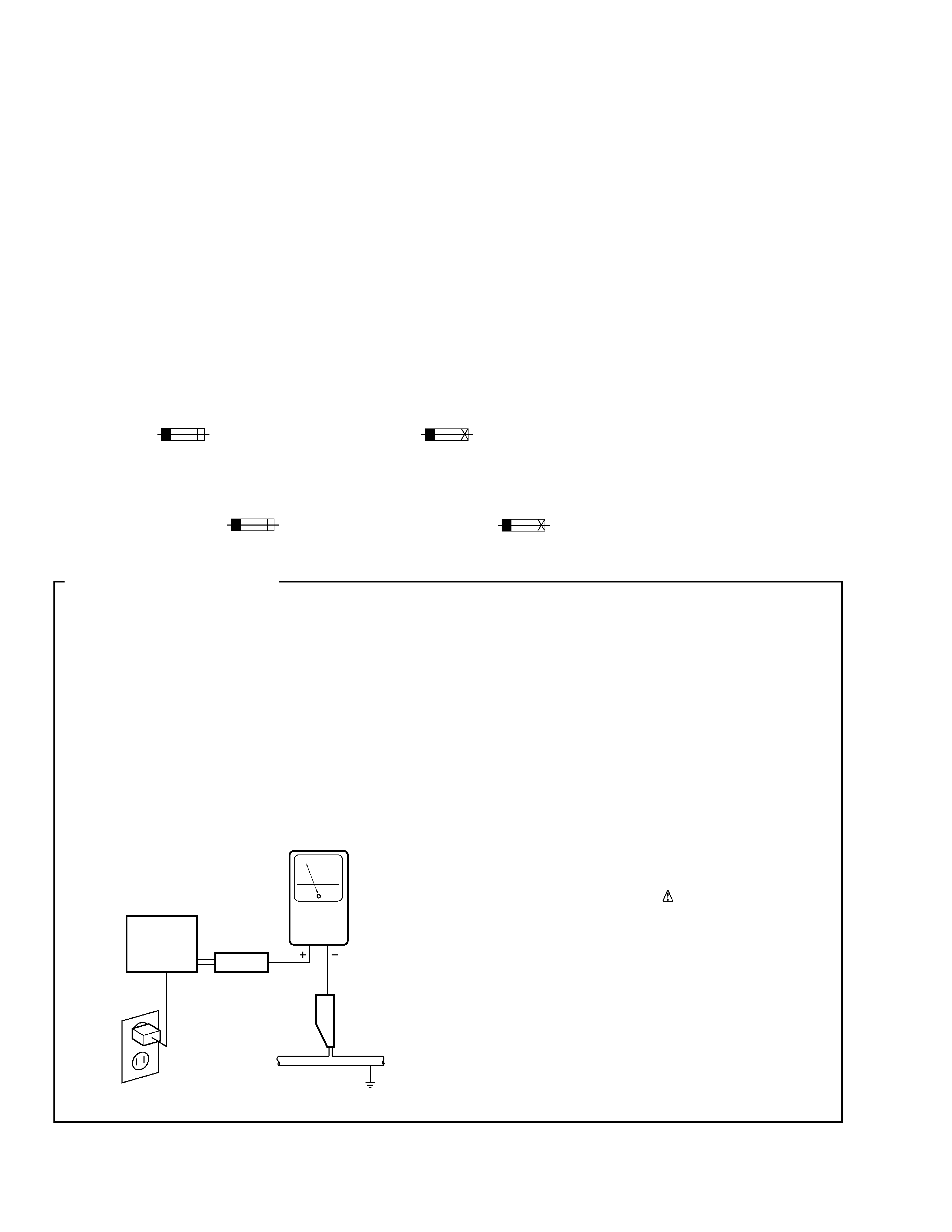
1. SAFETY PRECAUTIONS
The following check should be performed for the
continued protection of the customer and service
technician.
LEAKAGE CURRENT CHECK
Measure leakage current to a known earth ground
(water pipe, conduit, etc.) by connecting a leakage
current tester such as Simpson Model 229-2 or
equivalent between the earth ground and all exposed
metal parts of the appliance (input/output terminals,
screwheads, metal overlays, control shaft, etc.). Plug
the AC line cord of the appliance directly into a 120V
AC 60 Hz outlet and turn the AC power switch on. Any
current measured must not exceed 0.5 mA.
Device
under
test
Leakage
current
tester
Earth
ground
Reading should
not be above
0.5 mA
Also test with
plug reversed
(Using AC adapter
plug as required)
Test all
exposed metal
surfaces
AC Leakage Test
3
XC-L77
5
2
3
4
16
17
6
16
16
DISPLAY
UNIT
REMOTE
CONTROL
UNIT
11
15
16
14
13
10
1
12
9
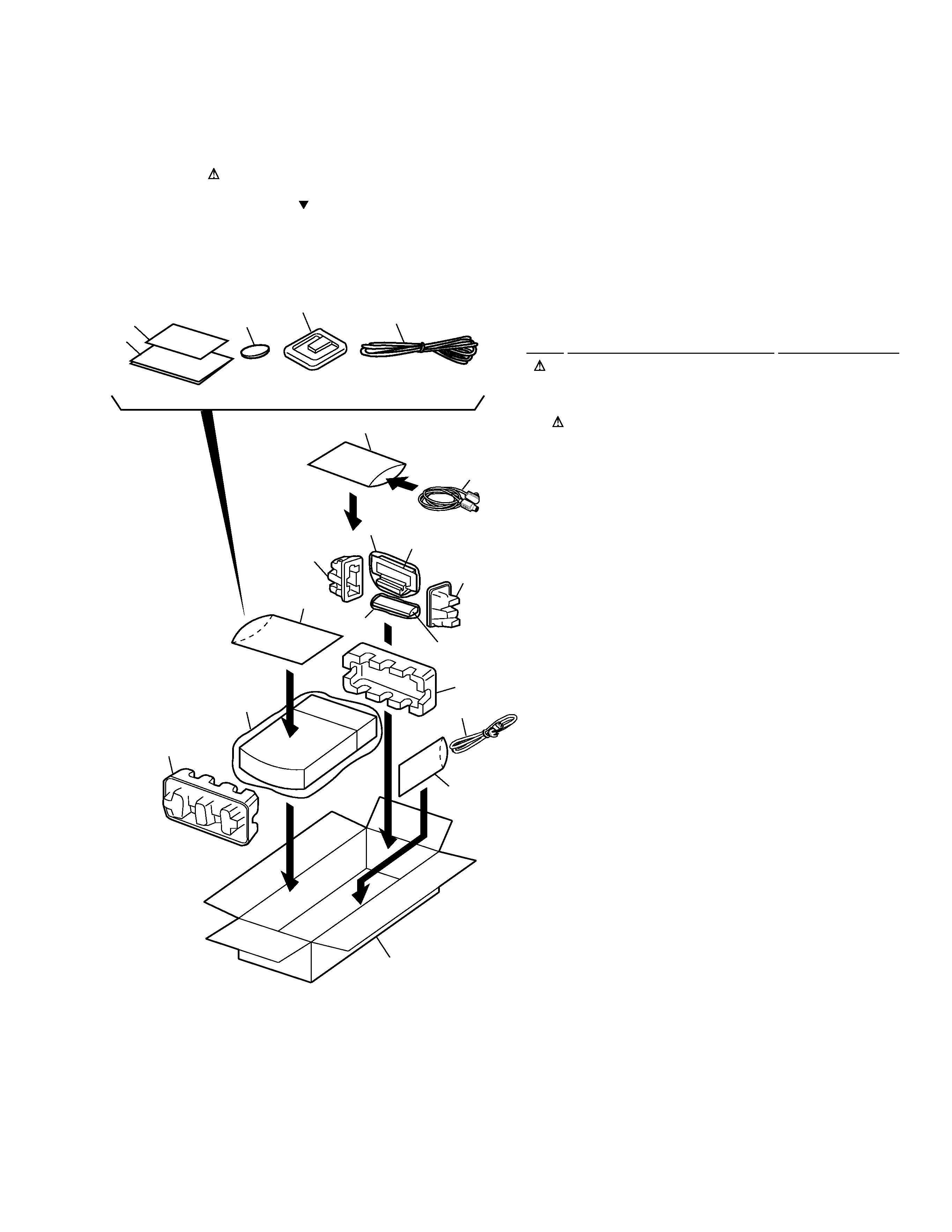
1
AC Power Cord
ADG7022
2
AM Loop Antenna
ATB7007
3
FM Wire Antenna
ADH7004
4
Display unit connecting cord
ADE7014
NSP
5
Lithium Battery(CR2025)
VEM1009
6
Operating Instructions
ARE7215
(English/French)
7
· · · · ·
8
· · · · ·
9
P Pad F
AHA7269
10
P Pad R
AHA7270
11
P Pad DISP L
AHB7031
12
P Pad DISP R
AHB7034
13
Packing Case
AHD7800
14
Packing Sheet
AHG7065
15
Polyethylene Bag
Z21-038
NSP
16
Polyethylene Bag
CEG1116
NSP
17
Warranty Card
ARY7023
2.1 PACKING
2. EXPLODED VIEWS AND PARTS LIST
NOTES:
· Parts marked by "NSP" are generally unavailable because they are not in our Master Spare Parts List.
· The mark found on some component parts indicates the importance of the safety factor of the part.
Therefore, when replacing, be sure to use parts of identical designation.
· Screws adjacent to mark on the product are used for disassembly.
· PACKING PARTS LIST
Mark No.
Description
Part No.
4
XC-L77
A
K
H
I
B
C
D
J
I
G
A
F
E
K
H
J
G
E
D
B
C
F
53 (1/2)
58
22
22
53 (2/2)
54
57
56
41
41
41
41
45
48
44
22
30
35
×2
60
4
16
34
33
33
32
33
18
11
20
22
23
25
22
21
19
17
29
29
39
52
51
3
6
31
22
41
38
37
36
15
Refer to "2.3 CD MECHA (1/2)"
"2.4 CD MECHA (2/2)" .
27
43
47
41
59
56
10
9
5
87
1
2
13
14
55
57
49
12
41
46
41
42
50
61
28
25
24
26
41
40
62
63
29
64
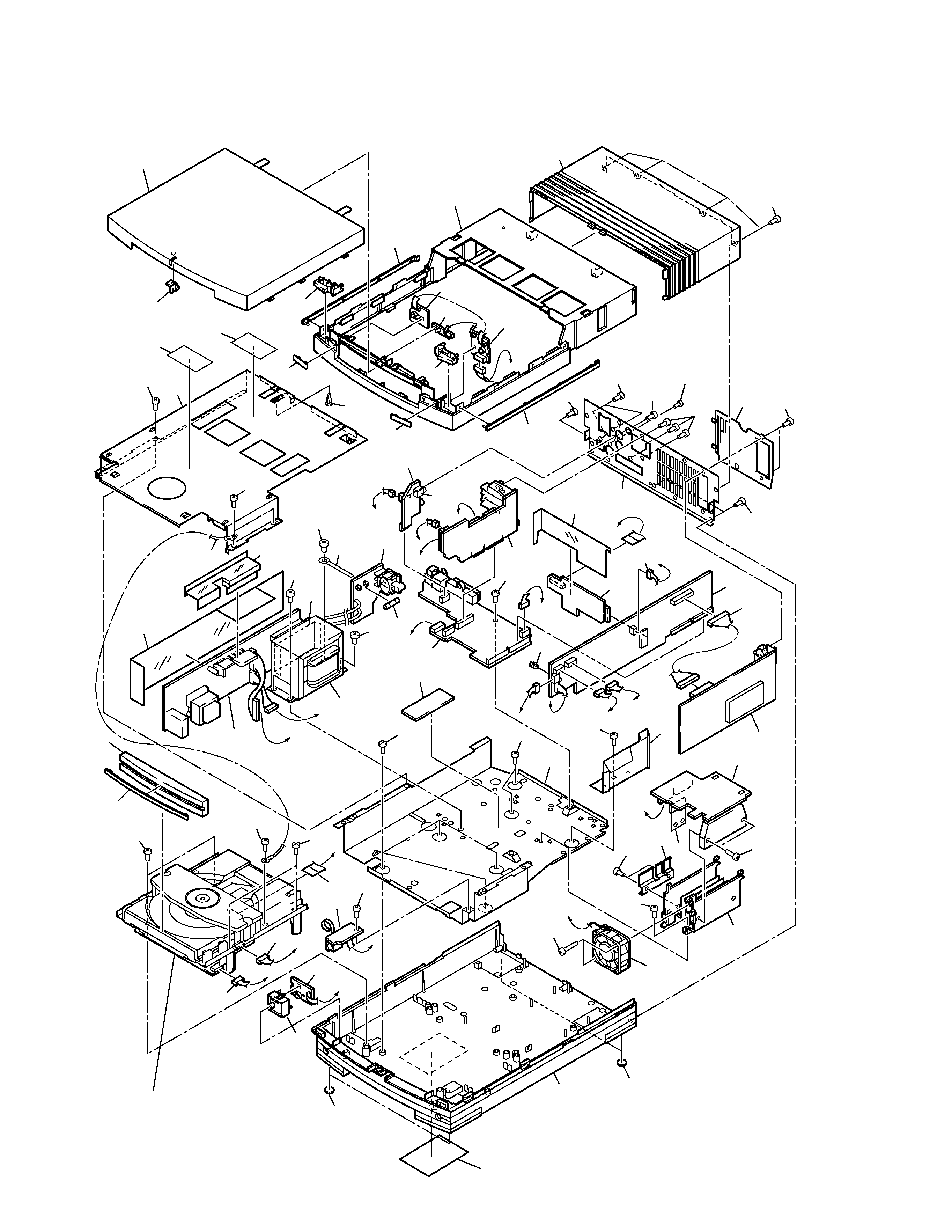
2.2 EXTERIOR

5
XC-L77
1
FM/AM TUNER UNIT
AXQ7225
2
AMP UNIT
AWU7376
3
STBY SW UNIT
AWU7386
4
SECONDARY UNIT
AWU7492
5
PRIMARY UNIT
AWU7493
6
HP UNIT
AWU7382
7
MAIN UNIT
AWU7491
8
RF UNIT
AWU7380
9
SPEAKER UNIT
AWU7377
10
AUX UNIT
AWU7381
11
CONNECTOR UNIT
AWU7494
12
KEYR UNIT
AWU7539
13
KEYL UNIT
AWU7384
14
BLUE IND. UNIT
AWU7385
15
CD MECHA
KSL-2130CCM
16
Power transformer (T1)
ATS7257
17
DC Fan Motor
AXM7014
18
Fuse (FU1 : 2.5A)
REK1112
NSP
19
Heat Sink
ANH7108
20
Screw
BBZ30P140FMC
21
Heat Plate
ANG7250
22
Screw
BBZ30P060FMC
23
Screw
BBZ30P300FMC
24
Bottom Base
AMA7010
25
Leg
AEB7090
26
Name Label
ARW7073
NSP
27
Bottom Plate
ANF7013
28
Jack (JA5551)
RKN1026
29
Screw
BBT30P060FZK
30
Sheet
AEE7034
31
Power Button Assy
AWL7049
32
TR Barrier
AEC7213
33
Screw
BBZ40P060FMC
NSP
34
Binder
ZCB-4772B
35
Power Barrier
AEC7196
36
Connector Assy
PG05KK-E20
37
Connector Assy
PG06KK-E20
38
16P Flat Flexible Cable/30V
ADD7216
NSP
39
Cord with Plug
DE010VF0
40
Screw
PDZ30P060FMC
41
Screw
VPZ30P080FZK
42
Connector Assy
PF03PP-Q22
43
Connector assy (J5101)
PG14KK-E07
44
Card Spacer
AEC7214
45
Rear Panel
ANC7831
46
Rear Cover
AAX7705
47
Screw
PCZ30P080FZK
48
Center Barrier
AEC7198
NSP
49
Top Plate
ANF7014
50
Push Rivet
AEC7221
51
Tray Panel
AAN7194
52
Tray Line
AAP7059
53
Top Panel Assy
AWL7046
54
Button Assy A (
6)
AWL7044
55
Button Assy B (
0)
AWL7045
56
Main Line
AAP7058
57
Front Line
AAP7066
58
CL Lens
AAX7704
59
Bonnet
AMA7012
60
Sub Barrier
AEC7197
61
65 Label
ARW7050
NSP
62
Fuse Caution
AAX7776
63
Acoustic Shield
AEB7130
64
TX Shield
AEC7243
· EXTERIOR PARTS LIST
Mark No.
Description
Part No.
Mark No.
Description
Part No.