Fig. 2
Fig. 3
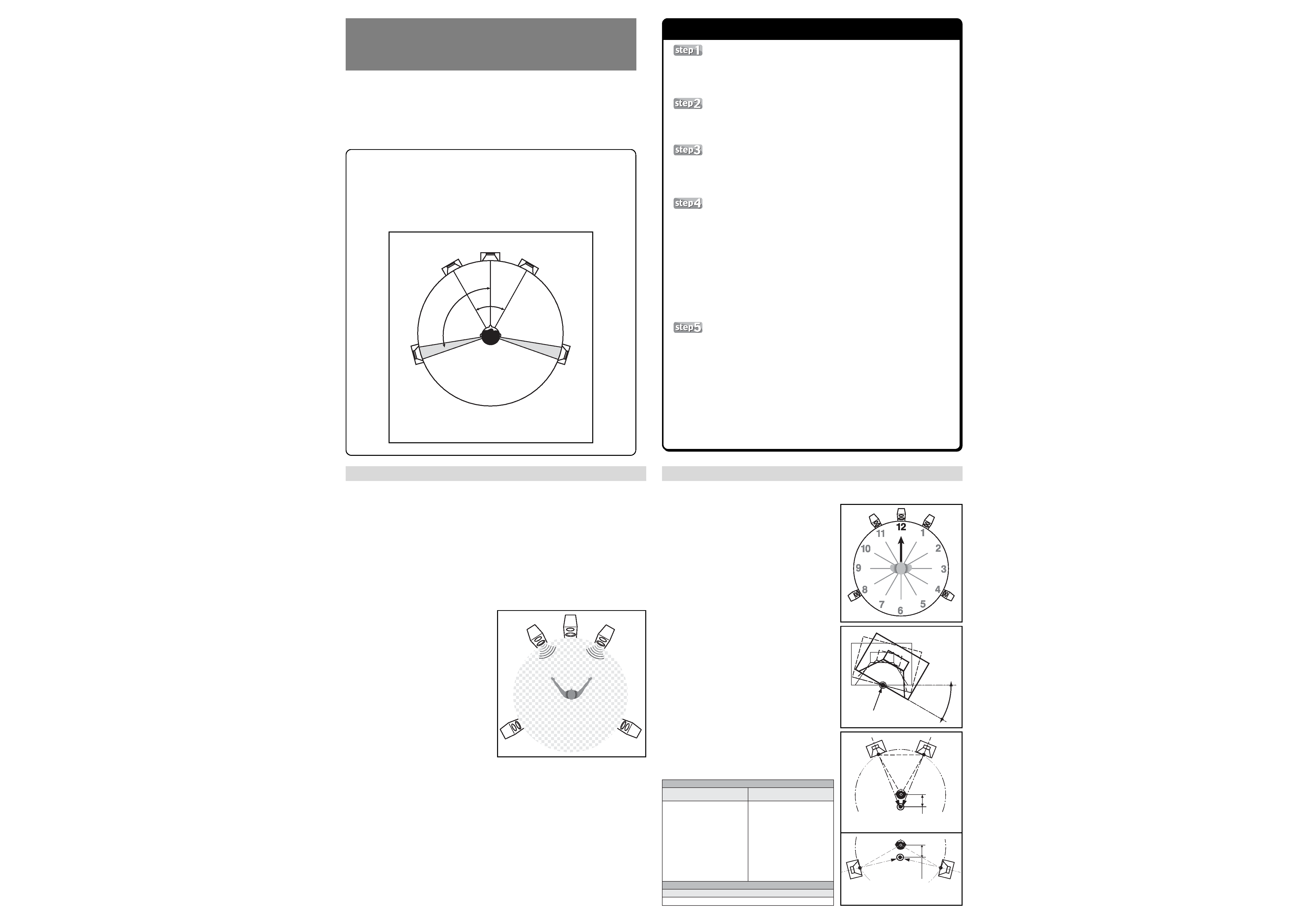
Speaker positions based on recommendations of International
Telecommunication UnionRadiocommunication sector (ITU-R).
FL
LS
RS
FR
C
60
°
100
°~120°
Fig. 4
Fig. 5
Fig.1 ITU-R recommended 5.1 ch speaker positions (ITU-R
BS.775-1)
Listening
position
Contents of Reference Calibration Disc
For Multi-Channel (DTS Signal)
Signals (Pulse) for
Adjusting Speaker Distance
Signals (Pulse) for Adjusting Speaker Distance
1 FL and FR
2 FL and C
3 FL and LS
4 LS and RS
1 FL and FR
1 12 o'clock
2 1 o'clock
3 2 o'clock
4 3 o'clock
5 4 o'clock
6 5 o'clock
7 6 o'clock
8 7 o'clock
9 8 o'clock
0 9 o'clock
- 10 o'clock
= 11 o'clock
~ 12 o'clock
Speaker Orientation
(Direction) Calibration Signals
For 2-Channel (Linear PCM Signal)
This unit is equipped with the Pioneer Multi-Channel Acoustic Calibration System (MCACC)
allowing it to automatically calibrate your speaker system to create the optimum sound
space. The reference calibration disc is furnished as an accessory, however, to allow you
to achieve the best possible sound settings. While listening to the signals recorded on the
disc, adjust the physical position and orientation of your speakers until they produce the
subjectively best possible sound space.
See the accompanying sidebar [Setting Procedure] for a concrete example of the setting
process.
This disc has been uniquely engineered by Pioneer with special calibration signals to allow
you to use your own sense of sound balance to adjust your speaker position (distance) and
orientation (direction) without the need for special measuring devices.
The speaker installation positions used in the recording of this disc are those recommended
for 5.1 ch sound by the ITU-R (see illustration), and believed to be appropriate for playback
of multi-channel audio. When using this disc to calibrate your speaker orientation (direc-
tion), it is necessary to set your speakers in the ITU-R positions, other positions may be
used, however, when setting the speaker distance.
Fine Adjustment of Speaker Distance
If surround back speakers are connected, set the surround back speaker setting to "none" only while performing
this adjustment.
1.
Connect the receiver and your DVD player via a digital connection, and set the receiver's play mode to the
pure decode mode, that is, STANDARD mode on this receiver. (Note: if surround effects or other signal pro-
cessing are implemented the sound imaging will change and proper adjustment will not be possible).
* The recorded calibration signals are pulse signals. To prevent speaker damage, do not raise the volume excessively.
2.
Play the reference calibration disc and display the menu screen.
For 2ch stereo speaker positions, press the remote control
2 35 keys to select the lower right "Linear PCM
(for two-channel)", then switch to the 2-channel menu screen. In this case, set the receiver's play mode for
stereo play ("STEREO" mode).
3.
Use the remote control
2 35 keys to select the FL/FR speakers on "1. Signals for Adjusting Speaker
Distance".
4.
The pulse signal will be played simultaneously from both channels; as shown in the accompanying illustra-
tion, face the two speakers producing the sound, spread your arms towards the speakers, and look at the
midpoint between the sounds. In this posture, your
ears will be in the proper position with respect to
the two speakers, thus allowing you to adjust the
sound correctly. Always use this posture when per-
forming adjustments.
Adjust the speaker distance delicately so that the
sound image from the two speakers appears to be
located precisely in the midpoint of the two speak-
ers when heard from the listening position (using
the posture described above).
When performing this adjustment, leave one
speaker in place as a reference speaker and move
the other speaker (normally, make each adjustment
distance only a few centimeters forward or back).
Normally, the front left (FL) speaker should be used
as a reference speaker. For example, when playing
the FL/FR signal, if the sound image appears to be
located more in the FR position, this means that
the FR speaker is too close; in this case, move it
slightly away from the listening position, while leav-
ing the FL speaker unmoved. When adjusting LS/
RS speakers, use the LS as the reference, and move
RS to adjust distance.
The calibration signals are divided into chapters by
channel; when calibrating sound, you may find it con-
venient to use your DVD player's chapter repeat function.
Adjust the FL/C
= FL/LS = LS/RS speakers in the same way.
* When surround speakers are located straight to the side of the listening position, the LS/RS adjustment should be performed
by taking one step forward and turning around. When L/R sounds are heard straight from the sides of the listening position,
the sound image tends to become located overhead, making it difficult to adjust properly. In other words, adjustments should
be made from a position where your spread hands are in a position more toward your front, not directly to your sides. If the
height of the two speakers is different, you might need to twist a bit so that you are able to stare straight into the midpoint of
the two speakers.
* In the case of FL/C and FL/LS speakers, you may find it more difficult to determine the sound image compared to FL/FR if the
sound image is hard to center, recheck your speaker connections. If one of the two speakers is connected with reversed phase
(+ and connections are reversed), it will be impossible to set the proper correct sound image. Also, listening conditions that
subject the two speakers to extreme differences in wall reflection may interfere with achieving a central sound image. Like-
wise, when the front and surround speakers are of different types, the FL/LS image may become ambiguous. In this case,
advance to adjusting the LS/RS speakers without attempting to further adjust the FL/LS speakers.
As noted above in Step 4, this adjustment should be performed only if your speaker settings are in accordance with
the ITU-R 5.1 ch placement angles shown in Fig. 1. Also note that the setting of sound image orientation is impaired
if each speaker's output level and distance are not correct; as a
result, be sure to set these items accurately before attempting to
adjust the speaker direction.
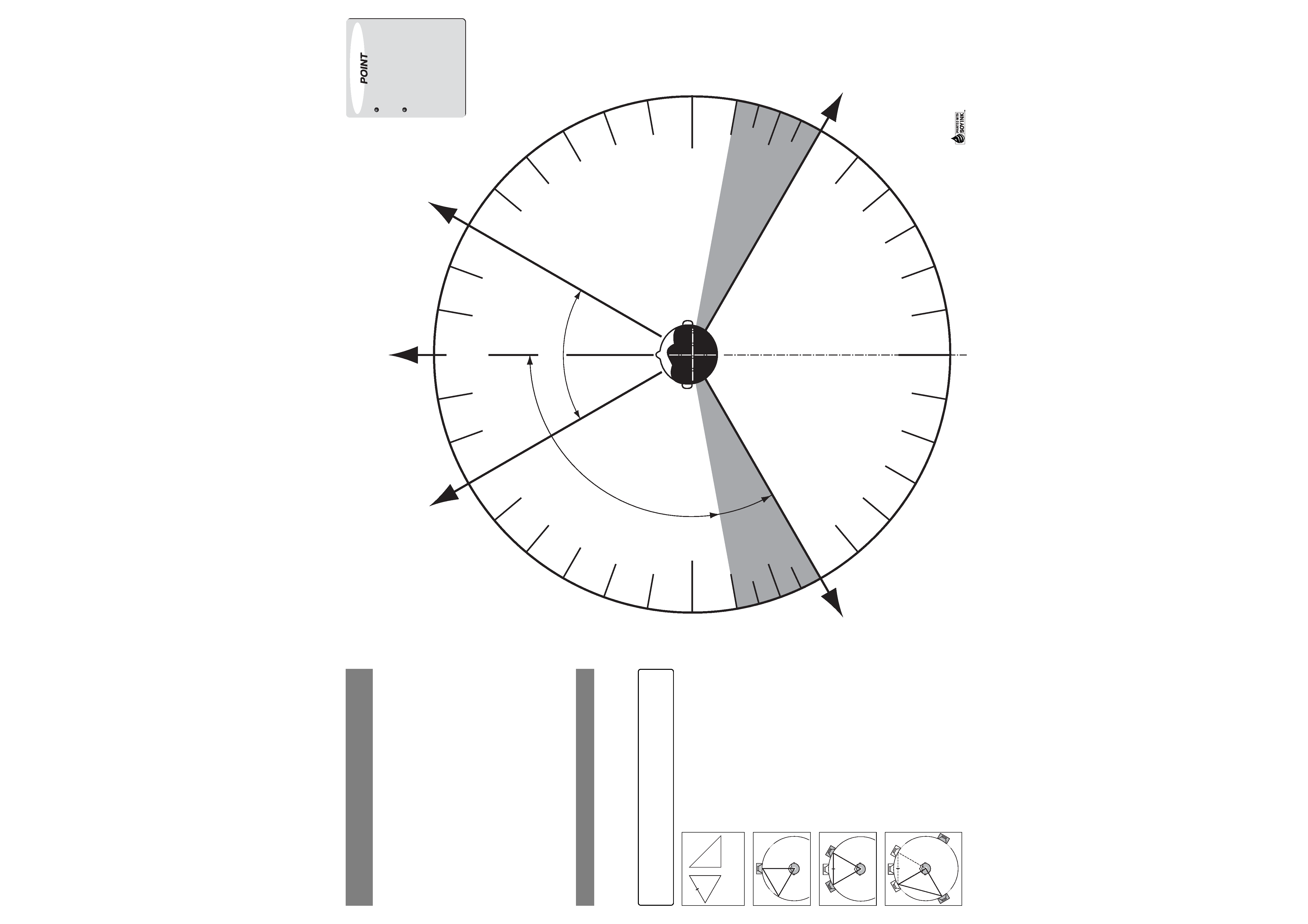
These instructions are based on the image of a large clock face,
with the listening position at the center and the "12:00" position
straight ahead.
1.
Connect the receiver and your DVD player via a digital
connection, and set the receiver's play mode to the pure de-
code mode, that is, STANDARD mode on this receiver. (Note:
if surround effects or other signal processing are implemented
the sound imaging will change and proper adjustment will
not be possible).
2.
Play the reference calibration disc and display the menu screen.
Use the remote control
2 35 keys to select the calibration
disc's item "2. Signals for Confirmation of Direction Definition",
for the "12 o'clock" position.
3.
Following an introductory narration, you will hear the sound
of a clock ticking and a male voice. They should be heard
coming directly from the 12 o'clock position.
4.
As you go through the subsequent chapters, the voice and
screen clock display will advance in a clockwise rotation (1
o'clock
= 2 o'clock = 3 o'clock ...). Confirm that the sound
and voice are heard as clearly coming from the specified
direction (for example, for the 3 o'clock position, the sound
should be heard coming from your immediate right). If the
sounds are not heard in their proper direction, adjust the
direction of your speakers. It may be impossible to accurately
adjust all of the 12 clock directions; emphasis should be placed
first on accurately adjusting the 4 cardinal directions (12 o'clock,
3 o'clock, 6 o'clock, and 9 o'clock), and then moving on to con-
firm the remaining in between positions.
* When adjusting speaker directions, change only the speaker angle, tak-
ing care not to change the position of the axis of rotation. The axis of
rotation should be located in the midpoint of the front surface of the
speaker (See Fig. 4).
* Results of experiments performed by a Pioneer-organized research group
have shown that favorable sound imaging can be produced when
speakers are set in the orientation depicted in Fig. 5. The actual sound
definition image, however, will change depending on the room
configuration and speakers used; as a result, various orientations should
be attempted while using this example as a reference.
Setting Procedure
Multi-Channel Audio
Speaker Setting Guide
Adjusting Speaker Direction
Speaker Position
When setting to the ITU-R positions, use the template on the reverse side of this
page; in other cases, select speaker positions while consulting the receiver's oper-
ating instructions. Also take into consideration the [Tips for Speaker Placement]
printed on the reverse side of this page.
Initiate the Multi-Channel Acoustic Calibration
System (MCACC)
Perform automatic sound space calibration in accordance with the receiver's
operating instructions.
Fine Adjustment of Speaker Position (Distance)
While listening to the calibration signals recorded on the reference calibration disc,
move the speaker to produce the best possible distance setting.
For specific adjustment methods, see the section [Fine Adjustment of Speaker
Distance].
Adjust Speaker Orientation (Direction)
While listening to the calibration signals recorded on the reference calibration disc,
adjust your speakers' direction as necessary to achieve the best possible sound
imaging. When the sense of direction is aligned, the spatial information contained
in the source will be accurately reproduced, resulting in a greatly improved sense
of presence.
For concrete adjustment methods, see the section [Adjusting Speaker Direction].
Note that sound imaging is a function of the angle of speakers from the listening
position. As noted earlier, this disc is recorded in accordance with ITU-R 5.1 ch
speaker positions, with the result that using other speaker positions will make it
impossible to properly adjust the sound imaging. This adjustment should only be
performed when speakers are placed at the angles recommended by ITU-R (see
Fig. 1).
Perform MCACC Once Again
Finally, implement the Multi-Channel Acoustic Calibration System (MCACC) once
again in order to even out all the individually performed settings and assure that
the optimally balanced sound field is achieved.
When the final step is completed, you will have produced a high-precision sound
field. Now sit back and enjoy the superb sense of live presence capable with multi-
channel audio.
This speaker calibration guide is designed to help the user manually perform fine adjustments of
speaker position while listening to recorded signals, so as produce even higher sound quality than
that automatically optimized with the MCACC system. Note that some settings may be difficult to
achieve due to differences in shape and furnishings of the listening room, and subjective differences
in the perception of sound.
Axis of rotation
Rotate
Straight lines from the speakers'
center axes intersect about 30-80 cm
behind the listening position.
Straight lines from the speakers'
center axes intersect about 30-80 cm
behind the listening position.
FL
LS
FR
RS
0
°
100
°
60
°
120
°
FL
RS
LS
FR
C(Front = 0 degrees)
Published by Pioneer Corporation.
Copyright © 2002 Pioneer Corporation.
All rights reserved.
Printed in Japan
<ARH7060-A>
FL
FR
LS
RS
Speaker Placement Using the ITU-R
Template
Ultimate ITU-R Settings
2m
2.83m
2m
2m
2m
Speakers should be installed a
minimum of 10 cm away from any
surrounding walls, on a solid, stable
surface.
Adjust
speakers
so
that
the
tweeters are approximately at ear
level. If the center speaker's height
cannot be set at the same level,
angle it so that it is pointing directly
at the listening position. Depending
on preference, surround speakers
may be set somewhat higher than
ear level if desired.
Tips for Speaker Placement
<Before Beginning>
Prepare two strings (the length of each string should be 3-4 times the
distance from the listening position to the front speakers), measuring tape
and felt pen for marking the string.
This method is more involved than the template method, but allows the
front 60-degree and surround 120-degree positions recommended by the
ITU-R to be set accurately.
As shown in Fig. 1, the ITU-R recommendations designate placement
angles for each speaker. The accompanying template can be used to easily
set speaker positions to these angles.
Before starting, prepare a string about 3 meters in length (the string should
be made of narrow, non-stretching material).
1 Open these Operating Instructions and align the ITU-R template center
with your listening position so that the position at 0 degrees is straight
ahead as shown.
2 Attach one end of the string to the center of the template and extend
the string out to the position at 0 degrees.
3 Install your center speaker along the extended string line (0 degrees).
4 Install your front speakers and surround speakers in the same way
along the appropriate extended string lines.
The ITU-R positioning method is based on the principle of setting each
speaker an equal distance from the listening position. It may be sufficient
to set the distance to the listening position electrically by means of
electronic delay circuits, but at least, the front two speakers and surround
two speakers should be set equal distances apart.
1 Using the string, prepare an equilateral triangle whose
leg length is equal to the distance from the listening
position to a front speaker. In the same way prepare a
right triangle (45°
× 45° × 90°) whose short leg length is
likewise equal to the distance from the listening position
to a front speaker. Use the felt pen to make a mark at the
midpoint of one of the legs of the equilateral triangle. (The
distances in the accompanying example illustration
represent those used when the distance from listening
position to front speaker is 2 meters).
(distance
x
1.414)
Equilateral
triangle
Right triangle
(45°
× 45° × 90°)
2 Install the center speaker at the front. Set the speaker dis-
tance with one leg of the equilateral triangle so that the
speaker is pointed directly toward the listening position.
3 Arrange the equilateral triangle so that the mark placed
on the midpoint of one leg of the triangle falls on the cen-
ter-line of the center speaker, then install the front speak-
ers at apexes of the two right/left angles as shown.
4 With the right triangle's 90° angle at the listening posi-
tion, place one of the shorter legs of the right triangle at
the centerpoint of the left front speaker (FL) as shown.
The other short side now points at the position where the
left surround speaker (LS) should be placed.
5 In the same way, align one short side of the right triangle
on the right side front speaker (FR) and install the right
surround speaker (RS) at the apex of the other short leg.