ORDER NO.
PIONEER CORPORATION 4-1, Meguro 1-chome, Meguro-ku, Tokyo 153-8654, Japan
PIONEER ELECTRONICS SERVICE, INC. P.O. Box 1760, Long Beach, CA 90801-1760, U.S.A.
PIONEER EUROPE NV Haven 1087, Keetberglaan 1, 9120 Melsele, Belgium
PIONEER ELECTRONICS ASIACENTRE PTE. LTD. 253 Alexandra Road, #04-01, Singapore 159936
PIONEER CORPORATION 2000
RRV2402
T-ZZM OCT. 2000 Printed in Japan
This product is component of system.
System
Service Manual
Remarks
- - - - -
RRV2340
RRV2402
RRV2332
Component
COMPACT MINI COMPONENT
STEREO DVD CASSETTE DECK RECIEVER
SPEAKER SYSTEM
SPEAKER SYSTEM
This service manual
SPEAKER SYSTEM
S-VS500VLR
FOR PRECAUTION OF
REASSEMBLY AND DISASSEMBLY
The cosmetic baffle assy is attached to the cabinet by 4 external
hexagon socket screws. To detach the cosmetic baffle assy,
loosen these screws by the hexagon screw driver. Then care-
fully disconnect the wires of the woofer or mid-range and
tweeter mounted on the cosmetic baffle assy. To attach the cos-
metic baffle assy, replace it on the cabinet correctly and secure
with 4 screws.
The woofer is attached to the cosmetic baffle assy together with
the cosmetic ring assy by 4 internal screws. To detach the
woofer (cosmetic ring assy), loosen these screws. To attach the
cosmetic ring assy, fit the notch of the cosmetic ring to the pro-
jection of the cosmetic baffle assy. To attach the woofer, face
its terminal downward. To attach the cosmetic ring assy and
woofer, replace it on the cosmetic baffle assy correctly and se-
cure with 4 screws.
The mid-range is attached to the cosmetic baffle assy by 4 inter-
nal screws. To detach it, unfasten those screws. When attaching
it, face its terminal downward.
The tweeter is attached to the cosmetic baffle assy by 2 internal
screws. To detach it, unfasten those screws. When attaching it,
face its terminal downward.
The network assy is attached to the bottom board by one internal
screw and adhesive. To detach it, unfasten that screw and pry it
out.To attach it, apply adhesive to the bottom board. Then press
it to the bottom board, and secure with one screw.When attach-
ing the network assy, do it carefully so that each wire is not
touched.
FRONT SP
SUPER WOOFER
X-VS500D
XR-VS500D
S-VS500VLR
S-A9LRC
XTL/NC
2
S-VS500VLR
Mark No.
Description
Part No.
Parts marked by "NSP" are generally unavailable because they are not in our Master Spare Parts List.
The
mark found on some component parts indicates the importance of the safety factor of the part.
Therefore, when replacing, be sure to use parts of identical designation.
NOTES:
PARTS LIST
Mark No.
Description
Part No.
NSP
CS ASSY (Front SP)
SMW1613
NSP
Cabinet
SMM1916
Network ASSY
SWN1653
Non Skid Pad
SEC1416
Gasket (Baffle Height)
SEC1447
Gasket (Baffle Wide)
SEC1502
Input Terminal
SKX1065
NSP
Stamped Model Label
SME3103
NSP
Model Label
SAN2894
NSP
Acoustic Absorbent
SMV2011
Cosmetic Baffle ASSY
SXB1414
NSP
Punching Net
SNC1184
NSP
Cosmetic Baffle
SNK2468
Speaker (Woofer)
W10DC61-53H
Speaker(Mid-range)
E52AP39-58F
Screw (for TW/MID)
BPZ40P080FMC
Screw (for Network ASSY)
BYC40P250FZB
Tapping Screw (for Cos. Baffle) SBA1162
NSP
Staple 80/8 BEA
ZMA-8008B
Top Protector
SHA2247
Bottom Protector
SHA2248
Protection Sheet
SHC1730
NSP
Polyethylene Bag S4
SHL1229
NSP
CS ASSY (Super Woofer)
SMW1614
NSP
Cabinet
SMM1917
Network ASSY
SWN1654
Non Skid Pad
SEC1416
Gasket (Baffle Wide)
SEC1503
Gasket (Baffle Height)
SEC1504
Input Terminal
SKX1066
NSP
Stamped Model Label
SME3104
NSP
Model Label
SAN2895
NSP
Acoustic Absorbent
SMV1916
Cosmetic Baffle ASSY
SXB1415
NSP
Duct
SMR1317
NSP
Cosmetic Baffle
SNK2469
Cosmetic Ring ASSY
SXB1419
NSP
Punching Net
SNC1183
NSP
Cosmetic Ring
SNK2486
Speaker
B18LU86-51F
Screw (for WF,Cos. Ring ASSY) BPZ40P160FMC
Screw (for Network ASSY)
BYC40P300FZB
Tapping Screw (for Cos. Baffle) SBA1162
NSP
Staple 80/8 BEA
ZMA-8008B
Top Protector
SHA2249
Bottom Protector
SHA2250
Protection Sheet
SHC1730
NSP
Polyethylene Bag S5
SHL1230
For Packing
Speaker Cord
SDS1096
Speaker Cord
SDS1097
Packing Case
SHG2313
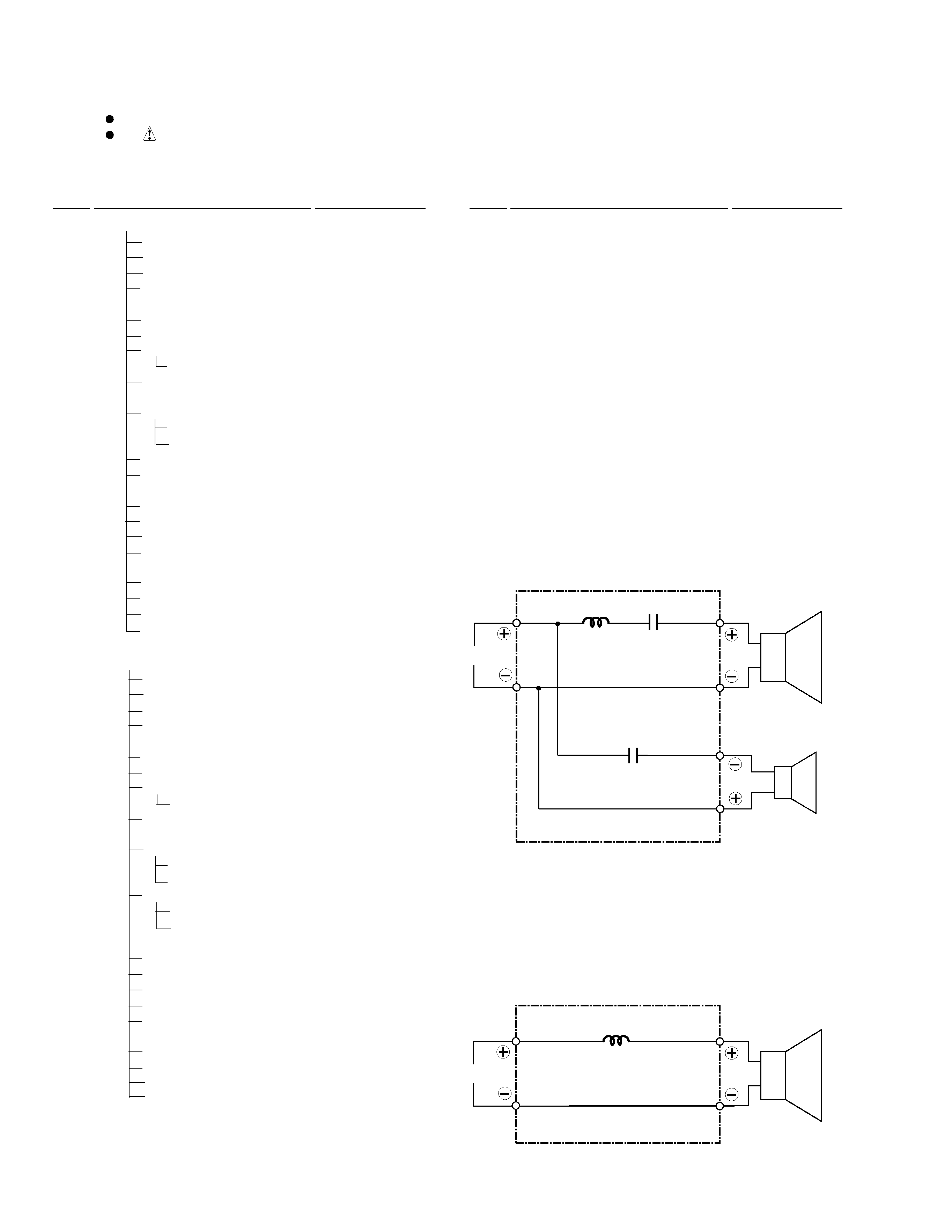
Network ASSY (SWN1653) for Front SP
SCHEMATIC DIAGRAM
Network ASSY (SWN1654) for Super Woofer
Mid-Range
I N
Red
Red
Black
Green
White
White
Tweeter
1.8
µF/63V
0.39mH
82
µF/50V
Woofer
I N
Red
Black
Blue
White
1.2mH
3
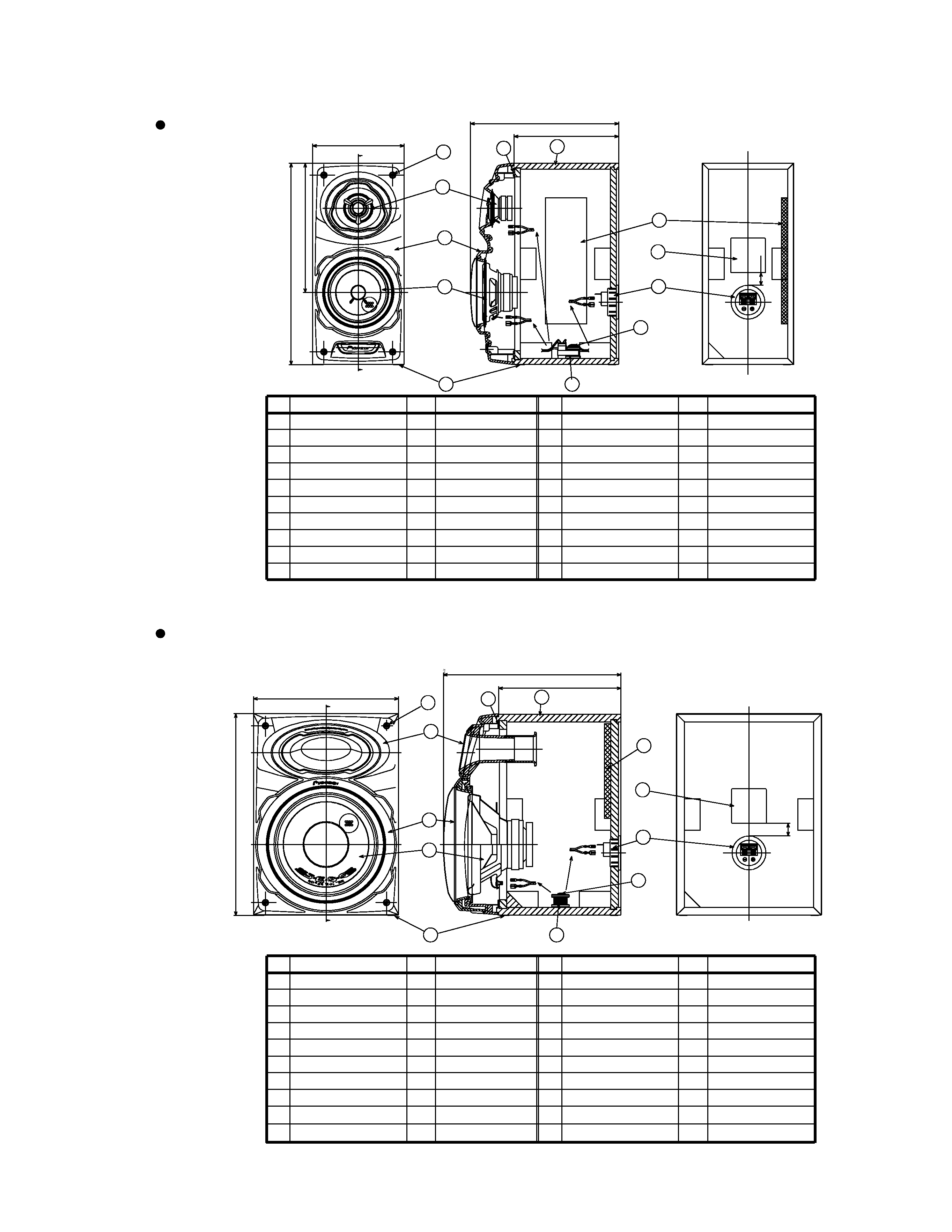
S-VS500VLR
PRODUCT APPEARANCE
8
9
10
11
12
13
14
15
16
17
18
19
20
7
Speaker (Mid-range)
Speaker (Woofer)
Cabinet
Cosmetic Baffle ASSY
Input Terminal
Acoustic Absorbent
Gasket
-----
Non Skid Pad
-----
6
5
4
3
2
1
Part name
Num.
No.
Remarks
Part name
Num.
No.
Remarks
8
9
10
Tapping Screw
Model Label
Network ASSY
Screw
1
1
1
1
1
1
2
4
4
1
1
1
11
12
13
14
15
16
17
18
19
20
7
Speaker
Cabinet
Cosmetic Baffle ASSY
Woofer Ring ASSY
Input Terminal
Acoustic Absorbent
Gasket
-----
Non Skid Pad
-----
B18LU86-51F
6
5
4
3
2
1
Part name
Num.
No.
Remarks
Part name
Num.
No.
Remarks
SBA1162
BYC40P300FZB
SUPER WOOFER
FRONT SPEAKER
320
205.2
145
3
7
9
12
2
4
1
6
5
11
13
14
(RED-WHITE CORD)
(GREEN-WHITE
CORD)
(RED-BLACK CORD)
235
166
(20)
320
230
2
7
9
12
1
4
3
6
5
11
13
14
(RED-BLACK CORD)
(BLUE-WHITE CORD)
194
281.5
(20)
Tapping Screw
Model Label
Network ASSY
Screw
4
1
1
1
SBA1162
BYC40P250FZB
E52AP39-58F
W10DC61-53H
1
1
1
1
1
1
2
4