ORDER NO.
PIONEER ELECTRONIC CORPORATION 4-1, Meguro 1-Chome, Meguro-ku, Tokyo 153-8654, Japan
PIONEER ELECTRONICS SERVICE, INC. P.O. Box 1760, Long Beach, CA 90801-1760, U.S.A.
PIONEER ELECTRONIC (EUROPE) N.V. Haven 1087, Keetberglaan 1, 9120 Melsele, Belgium
PIONEER ELECTRONICS ASIACENTRE PTE. LTD. 501 Orchard Road, #10-00 Wheelock Place, Singapore 238880
PIONEER ELECTRONIC CORPORATION 1998
c
RRV1986
MJ-L5
1. SAFETY INFORMATION ...................................... 2
2. EXPLODED VIEWS AND PARTS LIST ................ 3
3. SCHEMATIC DIAGRAM ..................................... 14
4. PCB CONNECTION DIAGRAM .......................... 32
5. PCB PARTS LIST ............................................... 44
6. ADJUSTMENT .................................................... 49
CONTENTS
7. GENERAL INFORMATION ................................ 59
7.1 IC ................................................................. 59
7.2 DIAGNOSIS ................................................. 75
7.3 DISASSEMBLY ........................................... 77
7.4 BLOCK DIAGRAM ....................................... 82
8. PANEL FACILITIES AND SPECIFICATIONS .... 84
T IZY AUG. 1998 Printed in Japan
SP-L5
THIS MANUAL IS APPLICABLE TO THE FOLLOWING MODEL(S) AND TYPE(S).
SURROUND PROCESSOR
· This products is a system component. It combined the following components.
MINIDISC RECORDER .................... MJ-L5
SURROUND PROCESSOR ............. SP-L5
· This products is a system component.
For the system composition, refer to the service manual RRV1997 for XC-L5.
· This product does not operate normally by itself. Please connect it to the STEREO CD RECEIVER XC-L5,
for adjustment and operation inspection. Otherwise damage may result.
DELAY
TIME
SFC
MODE
MODE
SFC
ON/OFF
Y
Y DOLBYSURROUND
P R O
· L O G I C
MINIDISC
ASES
7
0
6
¢
4
¡· +
·
1
MINIDISC RECORDER
Type
Model
Power Requirement
Remarks
MJ-L5
SP-L5
MYXK
AC220-230V
NVXK
AC230V
MJ-L5, SP-L5
2
IMPORTANT
THIS PIONEER APPARATUS CONTAINS
LASER OF CLASS 1.
SERVICING OPERATION OF THE APPARATUS
SHOULD BE DONE BY A SPECIALLY
INSTRUTED PERSON.
LASER DIODE CHARACTERISTICS
MAXIMUM OUTPUT POWER: 32 mw
WAVELENGTH: 785 nm
Laser pickup assy
The output power at the objective lens of this assy is 0.73 mW.
Control method of the current through a laser diode.
The resistor R105 on the MD CORE MAIN UNIT (For MD
mechanism assy) are for the limiting of current through a laser
diode.
Control method of the laser output power
The laser pickup assy provide the photo-diodes and APC (Auto
Power Control) circuit.
The photo-diode detect output of the laser diode then IC104 control
the APC circuit according to the signal voltage of the photo-diode via
IC101.
The Variable resistancer on the FPC in the Laser pickup assy can
be adjusted the output level of Laser diode to fix the rated output
level.
Laser Interlock Switch
The loading position detect switch S101 is set to " LOAD ON " (ON:
low level, OFF: high level) position, IC104 get the " LOAD " signal,
and hand the laser " LDON " signal to No. 9 terminal (LDON) of the
Laser pickup assy.
Then a laser diode can be lighted exept when the level of signal
"LOAD " is low.
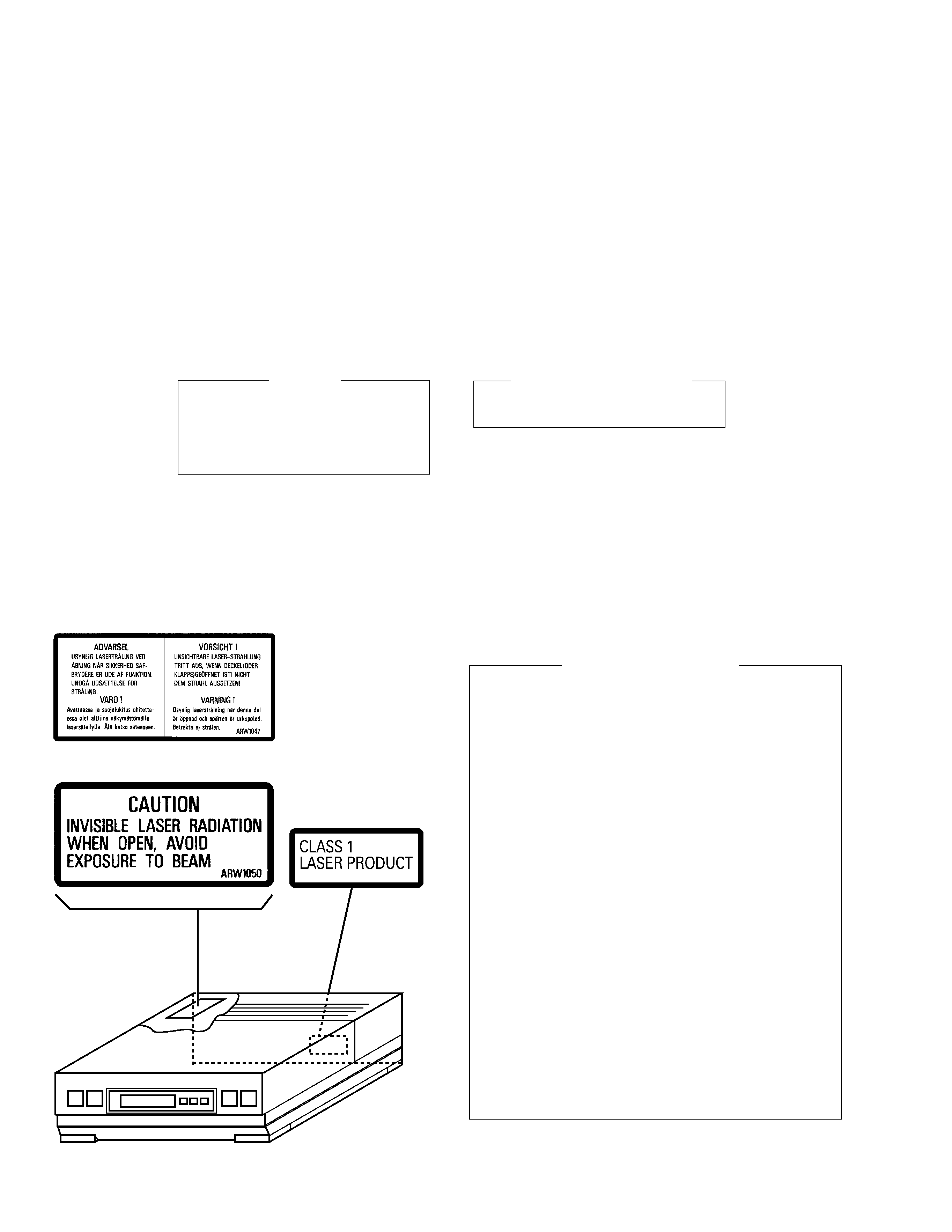
Additional Laser Caution
LABEL CHECK ( for MJ-L5/MYXK and NVXK only )
1. SAFETY INFORMATION
This service manual is intended for qualified service technicians; it is not meant for the casual
do-it-yourselfer. Qualified technicians have the necessary test equipment and tools, and have been
trained to properly and safely repair complex products such as those covered by this manual.
Improperly performed repairs can adversely affect the safety and reliability of the product and may
void the warranty. If you are not qualified to perform the repair of this product properly and safely, you
should not risk trying to do so and refer the repair to a qualified service technician.
WARNING
This product contains lead in solder and certain electrical parts contain chemicals which are known to the state of California to
cause cancer, bir th defects or other reproductive harm.
Health & Safety Code Section 25249.6 Proposition 65
Refer to page 50.
MJ-L5/MYXK
MJ-L5/NVXK
Printed on the Rear Panel
3
MJ-L5, SP-L5
1
2(1/2)
3(1/2)
3(2/2)
4
5
8
10
14
12
11
13
6
7
15
9
2(2/2)
NVXK only
NVXK only
MYXK only
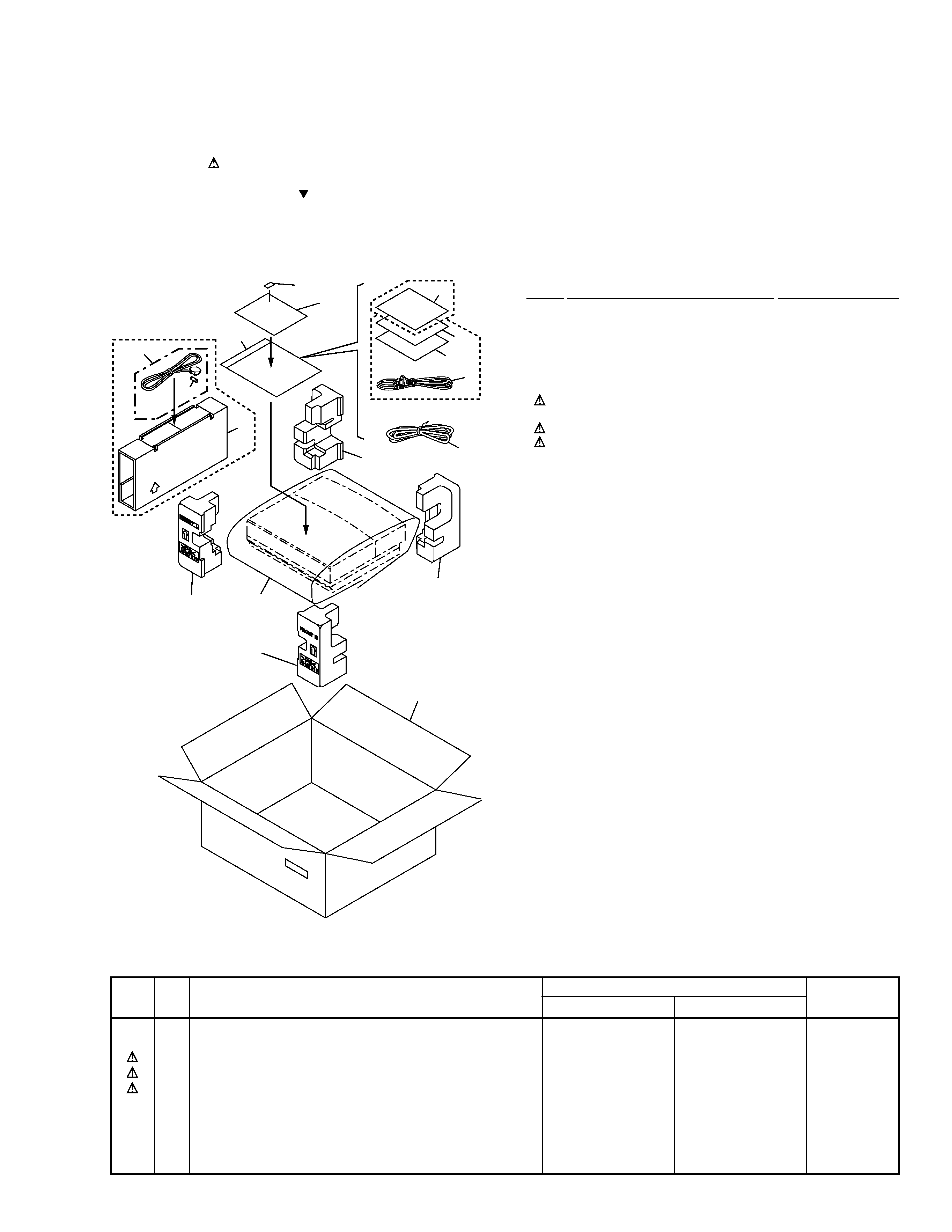
2.1 MINIDISC RECORDER (MJ-L5)
2.1.1 PACKING
(1) PACKING PARTS LIST
Mark No.
Description
Part No.
2. EXPLODED VIEWS AND PARTS LIST
NOTES:
· Parts marked by "NSP" are generally unavailable because they are not in our Master Spare Parts List.
· The mark found on some component parts indicates the importance of the safety factor of the part.
Therefore, when replacing, be sure to use parts of identical designation.
· Screws adjacent to mark on the product are used for disassembly.
(2) CONTRAST TABLE
MJ-L5/MYXK and MJ-L5/NVXK are constructed the same except for the following :
1
Packing Case
See Contrast table (2)
2
Pad F
AHA7219
3
Pad R
AHA7220
4
Sheet (750
×600×0.5)
Z23-007
5
Sub Packing
See Contrast table (2)
6
Power Cord
See Contrast table (2)
7
Optical Fiber Cable
RKX1031
8
Power Cord
See Contrast table (2)
9
Fuse (T5A)
See Contrast table (2)
10
Polyethylene Bag
Z21-038
(0.03
×230×340)
11
Operating Instructions
See Contrast table (2)
(English/French/German/Italian)
12
Operating Instructions
See Contrast table (2)
(English)
13
Operating Instructions
See Contrast table (2)
(Dutch/Swedish/Spanish/Portuguese)
NSP
14
Warranty Card
ARY7022
NSP
15
Serial Paper
RRW-168
Mark No.
Symbol and Description
Part No.
Remarks
MJ-L5/MYXK
MJ-L5/NVXK
1
Packing Case
AHD7630
AHD7631
5
Sub Packing
Not used
AHD7618
6
Power Cord
ADG7010
Not used
8
Power Cord
Not used
ADG7009
9
Fuse (T5A)
Not used
AEK7001
11
Operating Instructions (English/French/German/Italian)
ARE7173
Not used
12
Operating Instructions (English)
Not used
ARB7154
13
Operating Instructions (Dutch/Swedish/Spanish/Portuguese)
ARE7174
Not used
4
MJ-L5, SP-L5
Refer to
"2.1.3 TOP PANEL ASSY".
25
15
14
14
13
13
13
11
10
8
9
25
16
13
12
25
21
25
24
24
27
6
25
5
2
26
26
26
17
18
3
4
1
25
16
19
25
20
16
7
Refer to
"2.1.4 MD MECHANISM ASSY".
23
22
26
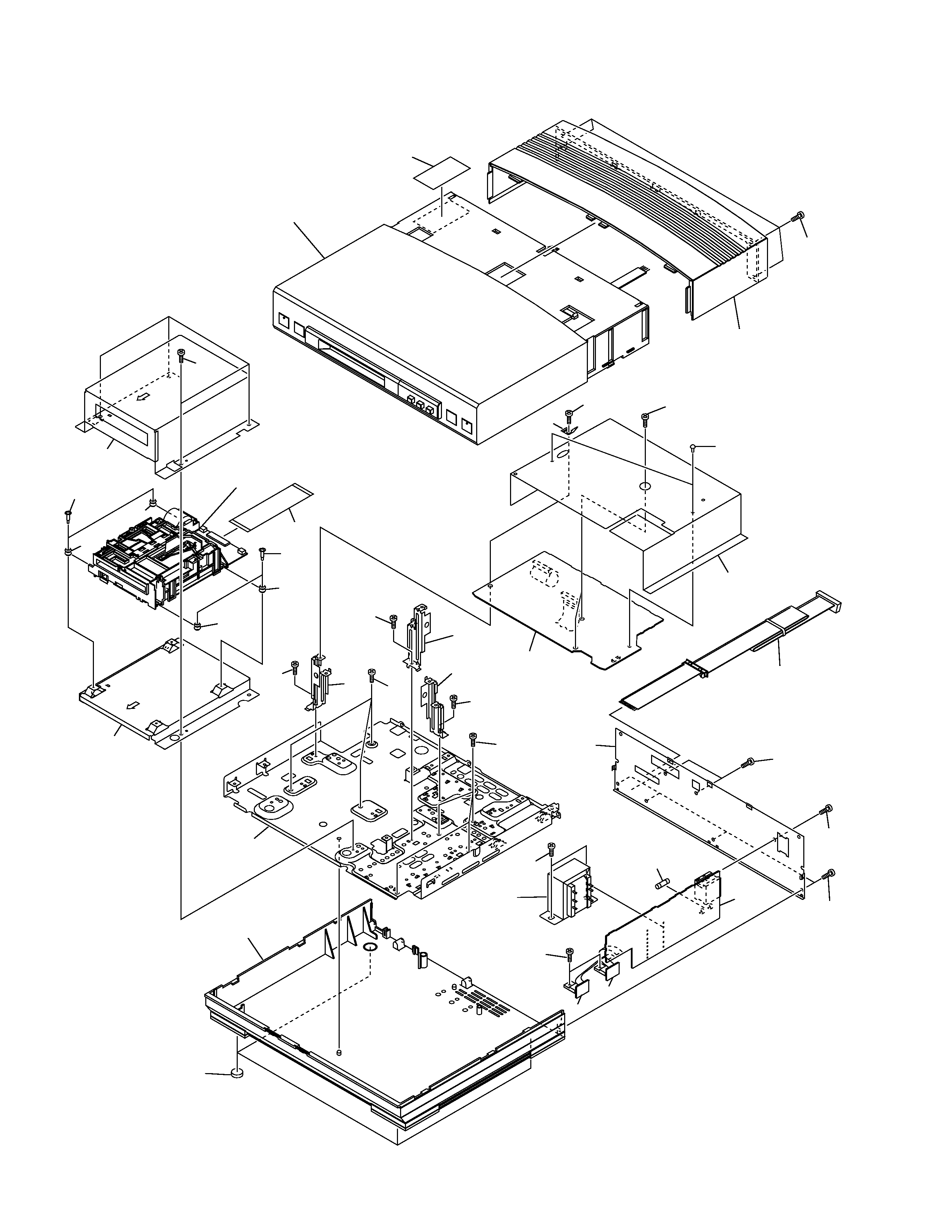
2.1.2 EXTERIOR
5
MJ-L5, SP-L5
(1) EXTERIOR PARTS LIST
Mark No.
Description
Part No.
1
MD MAIN Unit
AWU7106
2
MD TRANS Unit
AWU7107
3
MD REG1 Unit
AWU7154
4
MD REG2 Unit
AWU7155
5
Fuse (FU1 : T200mA/250V)
AEK1047
6
Power Transformer (T1)
ATT7031
NSP
7
MD MECHANISM Assy
AXA7069
8
Bottom Base
AMA7006
9
Leg
AEB7090
NSP
10
Bottom Plate
ANF7010
11
MD Base
ANG7191
12
30P F·F·C/30V
ADD7097
13
Float Rubber
REB1328
14
Float Screw
RBA1133
15
MD Shield
ANG7192
Mark No.
Description
Part No.
16
Angle
ANG7189
17
Rear Panel
See Contrast table (2)
18
Cord With Plug (J1)
ADE7026
19
Shield Barrier
AEC7164
20
Rivet
VEC1178
21
Earth Plate
ANG7168
22
Bonnet
AMA7007
NSP
23
Caution Label
See Contrast table (2)
24
Screw
BPZ30P060FZK
25
Screw
BBZ30P060FMC
26
Screw
VPZ30P080FZK
27
Screw
BBZ40P060FMC
(2) CONTRAST TABLE
MJ-L5/MYXK and MJ-L5/NVXK are constructed the same except for the following :
Mark No.
Symbol and Description
Part No.
Remarks
MJ-L5/MYXK
MJ-L5/NVXK
17
Rear Panel
ANC7675
ANC7676
NSP
23
Caution Label
ARW1047
ARW1050