ORDER NO.
PIONEER CORPORATION 4-1, Meguro 1-chome, Meguro-ku, Tokyo 153-8654, Japan
PIONEER ELECTRONICS SERVICE, INC. P.O. Box 1760, Long Beach, CA 90801-1760, U.S.A.
PIONEER EUROPE NV Haven 1087, Keetberglaan 1, 9120 Melsele, Belgium
PIONEER ELECTRONICS ASIACENTRE PTE. LTD. 253 Alexandra Road, #04-01, Singapore 159936
PIONEER CORPORATION 2001
c
S-HTD1
RRV2456
T ZZV MAY 2001 Printed in Japan
SPEAKER SYSTEM
XMD/EW
XJC/E
XJC/NC
FOR PRECAUTION OF
REASSEMBLY AND DISASSEMBLY
The grille assy is attached to the cabinet by its bosses applied
with adhesive. To detach it, pry it open by inserting a flat blade
screwdriver into lower slot. To attach it, apply adhesive to the
holes on the baffle. Then press it to the bafle.
The woofer is attatched to the baffle by 4 external screws. To
detach it ,unfasten those screws. When attaching it, face its ter-
minal downward.
The tweeter is attached to the baffle by 2 external screws. To
detach it ,unfasten those screws. When attaching it, face its ter-
minal downward.
(Front SP)
Component
System
Service Manual
Remarks
DVD SURROUND SYSTEM
X-HTD1
DVD RECEIVER
XV-HTD1
RRV2460
SPEAKER SYSTEM
S-HTD1
RRV2456
This service manual
This product is component of system.
The woofer is attached to the rear baffle by 4 external screws.
To detach it ,unfasten those screws. When attaching it, face its
terminal rightward.
(Sub Woofer)
The grille assy is attached to the cabinet by its bosses applied
with adhesive. To detach it, pry it open by inserting a flat blade
screwdriver into lower slot. To attach it, apply adhesive to the
holes on the baffle. Then press it to the bafle.
The speaker is attached to the baffle by 4 external screws. To
detach it ,unfasten those screws. When attaching it, face its ter-
minal leftward or rightward.
(Center SP)
The grille assy is attached to the cabinet by its bosses applied
with adhesive. To detach it, pry it open by inserting a flat blade
screwdriver into lower slot. To attach it, apply adhesive to the
holes on the baffle. Then press it to the bafle.
The speaker is attached to the baffle by 4 external screws. To
detach it ,unfasten those screws. When attaching it, face its ter-
minal downward.
(Rear SP)
S-HTD1
2
Mark No.
Description
Part No.
For Packing
Parts marked by "NSP" are generally unavailable because they are not in our Master Spare Parts List.
The
mark found on some component parts indicates the importance of the safety factor of the part.
Therefore, when replacing, be sure to use parts of identical designation.
NOTES:
PARTS LIST
NSP
CS ASSY (Front SP)
See Contrast table (2)
NSP
CS ASSY (Sub Wf))
See Contrast table (2)
NSP
CS ASSY (Center SP)
See Contrast table (2)
NSP
CS ASSY (Rear SP)
See Contrast table (2)
Speaker Wire (for Front SP)
SDS1102
Speaker Wire (for Sub Wf)
SDS1103
Speaker Wire (for Center SP)
SDS1104
Speaker Wire (for Rear SP)
SDS1105
Top Protector
SHA2289
Upper Middle Protector
SHA2290
Lower Middle Protector
SHA2291
Bottom Protector
SHA2292
Packing Case
See Contrast table (2)
Protection Sheet (for Front SP)
SHC1773
Protection Sheet (for Sub Wf)
SHC1774
Protection Sheet (for Center SP)
SHC1775
Protection Sheet (for Rear SP)
SHC1776
(1) PARTS LIST
(2) CONTRAST TABLE
S-HTD1/XMD/EW, S-HTD1/XJC/E and S-HTD1/XJC/NC models are constructed the same except for th following:
* 1 : Refer to " CS Assy (Front SP) ".
* 2 : Refer to " CS Assy (Sub Wf) ".
* 3 : Refer to " CS Assy (Center SP)".
* 4 : Refer to " CS Assy (Rear SP)".
NSP
CS ASSY (Front SP)
SMW1633*1
SMW1641*1
SMW1645*1
*1 Constructed same.
NSP
CS ASSY (Sub Wf)
SMW1634*2
SMW1642*2
SMW1646*2
*2 Constructed same.
NSP
CS ASSY (Center SP)
SMW1635*3
SMW1643*3
SMW1647*3
*3 Constructed same.
NSP
CS ASSY (Rear SP)
SMW1636*4
SMW1644*4
SMW1648*4
*4 Constructed same.
Packing Case
SHG2344
SHG2353
SHG2354
Mark
Symbol and Description
Part No.
S-HTD1/XMD/EW S-HTD1/XJC/E
S-HTD1/XJC/NC
Remarks

S-HTD1
3
CS ASSY (Front SP)
PARTS LIST
Speaker (Tw)
E52AP39-59F
Speaker (Wf)
W10DC61-56F
Network Assy
SWN1667
Input Terminal
SKX1068
Grille Assy
SMG1717
Grille Sash
SNK2516
Screw (for Grille Sash)
BPZ40P120FZB
Screw (for Speaker)
BYC40P140FZB
Mark No.
Description
Part No.
CS ASSY (Sub Wf)
PARTS LIST
Speaker
A14LU83-51F
CS Cord
SDD1301
Gasket
SEC1527
Input Terminal
SKX1070
Cosmetic Baffle
SNK2519
Screw (for Speaker)
BYC40P140FZB
Mark No.
Description
Part No.
CS ASSY (Center SP)
PARTS LIST
Speaker
D87DU54-52F
CS Cord
SDD1300
Input Terminal
SKX1069
Grille Assy
SMG1718
Grille Sash
SNK2517
Screw (for Grille Sash)
BPZ40P120FZB
Screw (for Speaker)
BYC40P140FZB
Mark No.
Description
Part No.
CS ASSY (Rear SP)
PARTS LIST
Speaker
D87DC54-58F
CS Cord
SDD1302
Input Terminal
SKX1071
Grille Assy
SMG1719
Grille Sash
SNK2518
Metal Fixture
SNA1400
Screw (for Metal Fixture)
BYC35P140FZB
Screw (for Grille Sash)
BPZ40P120FZB
Screw (for Speaker)
BYC40P140FZB
Mark No.
Description
Part No.
S-HTD1
4
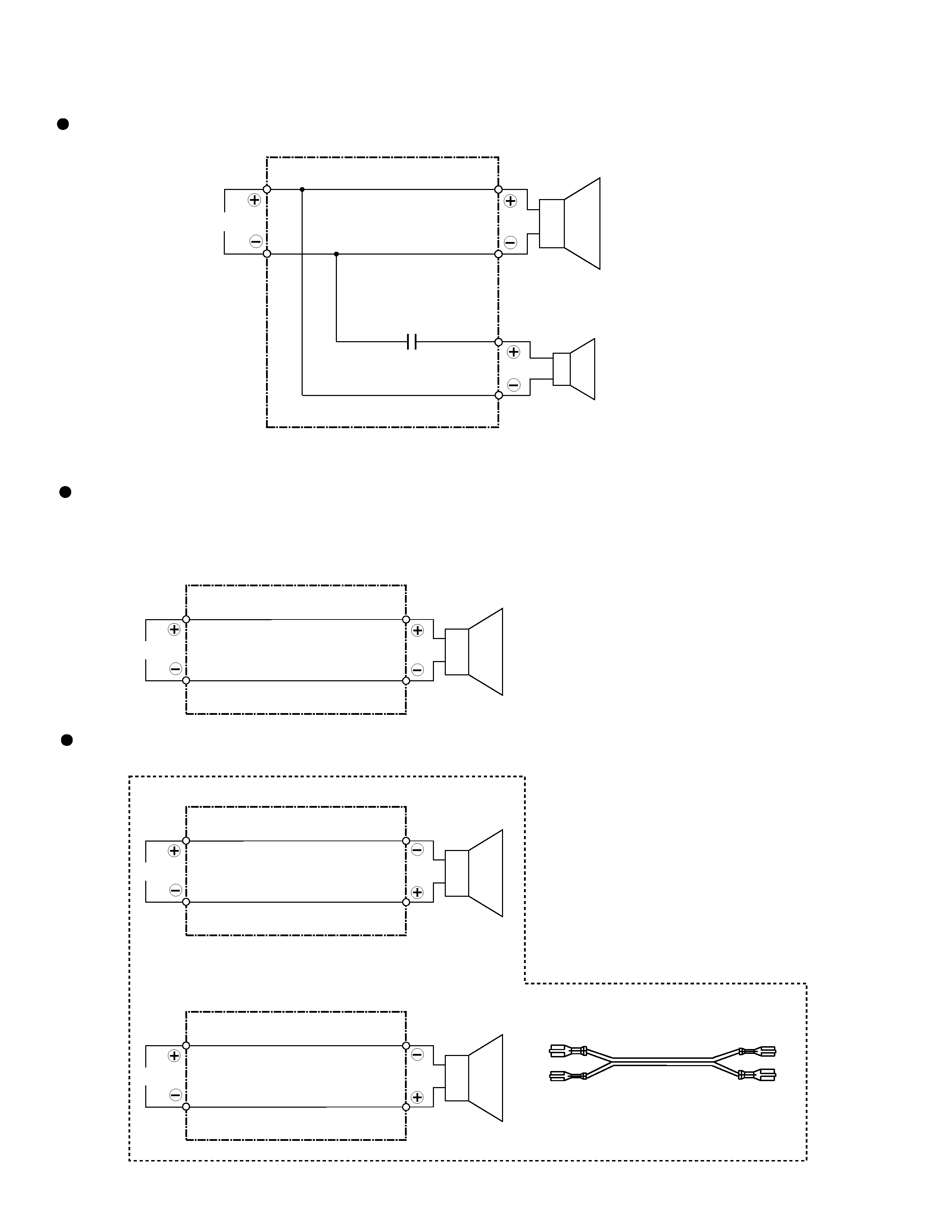
I N
Blue
Red
White
White
Woofer
Tweeter
1.2
µF/63V
INPUT
Blue
White
Full-Range
Speaker Wire
INPUT
Blue
Or
White
Full-Range
Speaker Wire
INPUT
White
Blue
Full-Range
Speaker Wire
SDD1301 Product Appearance
The CS cord terminal of SDD1301 is reversed.
Then, the color of the CS cord is alternative.
In
(Out)
Out
(In)
Blue
White
SCHEMATIC DIAGRAM
CS Cord (Center /Rear)
CS Cord (Sub Wf)
Network ASSY (SWN1667)
(SDD1300/SDD1302)
(SDD1301)
S-HTD1
5
No.
1
2
3
4
5
6
1
3
10
1
1
1
1
1
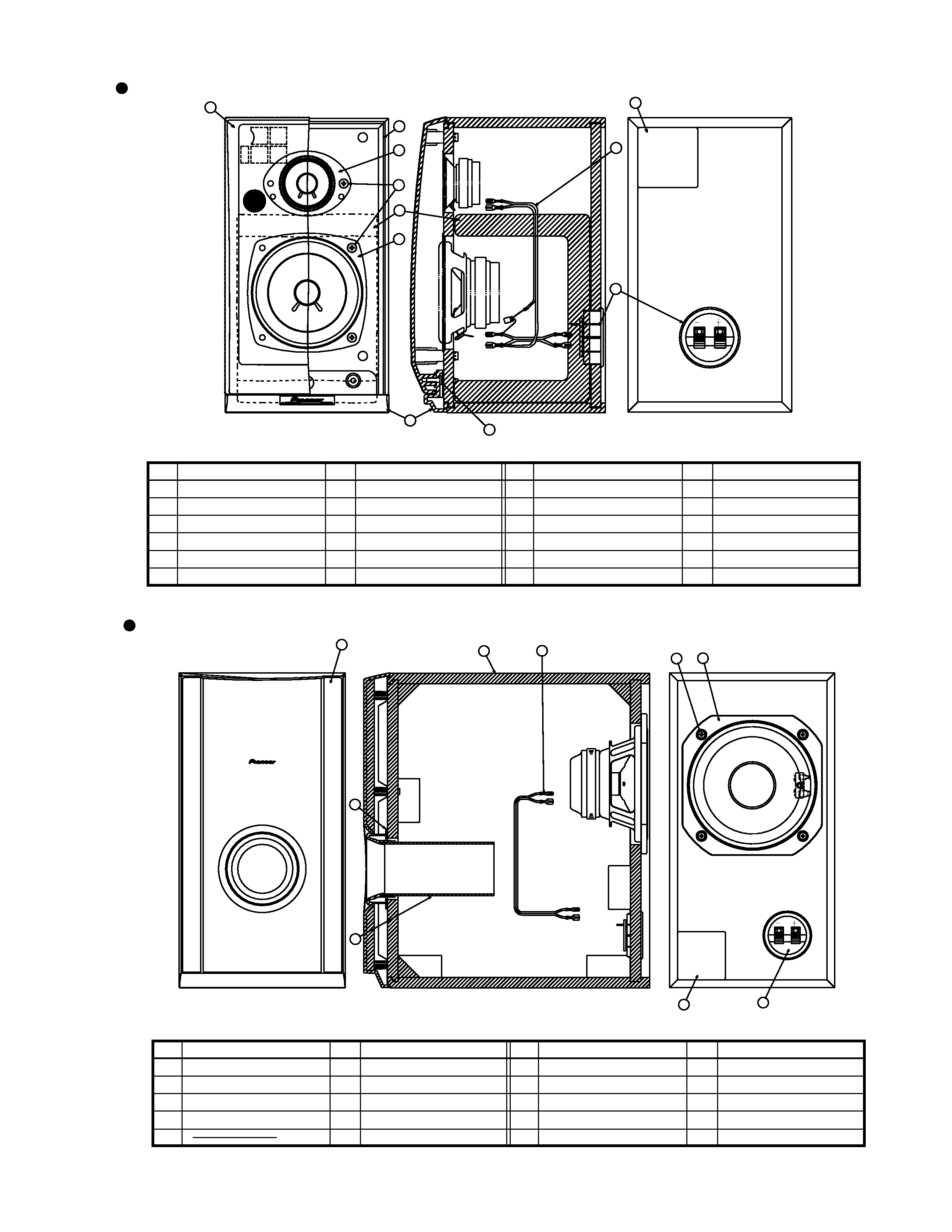
Cabinet
SWN1667
SNK2516
SMG1717
Polyester Fiber t=20
SKX1068 (Red - Black)
Network Assy
Grille Sash
Grille Assy
Acoustic Absorbent
Input Terminal
Speaker (Wf)
Speaker (Tw)
Screw
BYC40P140FZB
W10DC61-56F
E52AP29-59F
BPZ40P120FZB
Screw
Model Label
1
1
6
2
1
7
8
9
10
11
Num
Part name
Remarks
No.
Num
Part name
Remarks
6
2
11
4
1
8
9
5
7
No.
1
2
3
4
5
1
1
1
1
Paper Tube
t=2
57×61×125
SNK2519
Gasket
Cosmetic Baffle
Cabinet
Speaker
Screw
CS Cord
A14LU83-51F
BYC40P140FZB
SDD1301
SKX1070 (Gray-Black)
Input Terminal
Model Label
1
4
1
1
1
6
7
8
9
10
Num
Part name
Remarks
No.
Num
Part name
Remarks
10
9
7
6
8
4
1
2
3
PRODUCT APPEARANCE
CS ASSY (Front SP)
CS ASSY (Sub Wf)