ORDER NO.
PIONEER CORPORATION 4-1, Meguro 1-chome, Meguro-ku, Tokyo 153-8654, Japan
PIONEER ELECTRONICS (USA) INC. P.O. Box 1760, Long Beach, CA 90801-1760, U.S.A.
PIONEER EUROPE NV Haven 1087, Keetberglaan 1, 9120 Melsele, Belgium
PIONEER ELECTRONICS ASIACENTRE PTE. LTD. 253 Alexandra Road, #04-01, Singapore 159936
PIONEER CORPORATION 2001
RRV2562
5.1ch SPEAKER SYSTEM(SATELLITE SPEAKER/POWERED SUBWOOFER)
S-HS01
1. SAFETY INFORMATION ...................................... 2
2. EXPLODED VIEWS AND PARTS LIST ................ 3
3. SCHEMATIC DIAGRAM ........................................ 8
4. PCB CONNECTION DIAGRAM .......................... 10
5. PCB PARTS LIST ............................................... 13
6. ADJUSTMENT .................................................... 13
CONTENTS
7. GENERAL INFORMATION ................................ 14
7.1 DISASSEMBLY ........................................... 14
8. PANEL FACILITIES AND SPECIFICATIONS .... 15
T ZZV OCT. 2001 Printed in Japan
THIS MANUAL IS APPLICABLE TO THE FOLLOWING MODEL(S) AND TYPE(S).
Type
Model
S-HS01
MLXTW/E
SDBXTW/E
AC220 230V
Ó
AC110V/120127V/220V/240V
Ó
With the voltage selector at the rear plate
Power Requirement
The voltage can be converted by
the following method.
2
S-HS01
1. SAFETY INFORMATION
This service manual is intended for qualified service technicians; it is not meant for the casual
do-it-yourselfer. Qualified technicians have the necessary test equipment and tools, and have been
trained to properly and safely repair complex products such as those covered by this manual.
Improperly performed repairs can adversely affect the safety and reliability of the product and may
void the warranty. If you are not qualified to perform the repair of this product properly and safely, you
should not risk trying to do so and refer the repair to a qualified service technician.
WARNING
This product contains lead in solder and certain electrical parts contain chemicals which are known to the state of California to
cause cancer, birth defects or other reproductive harm.
Health & Safety Code Section 25249.6 Proposition 65
NOTICE
(FOR CANADIAN MODEL ONLY)
Fuse symbols
(fast operating fuse)
and/or
(slow operating fuse) on PCB indicate that replacement
parts must be of identical designation.
REMARQUE
(POUR MODÈLE CANADIEN SEULEMENT)
Les symboles de fusible
(fusible de type rapide)
et/ou
(fusible de type lent) sur CCI indiquent que
les pièces de remplacement doivent avoir la même désignation.
ANY MEASUREMENTS NOT WITHIN THE
LIMITS OUTLINED ABOVE ARE INDICATIVE
OF A POTENTIAL SHOCK HAZARD AND
MUST BE CORRECTED BEFORE RETURN-
ING THE APPLIANCE TO THE CUSTOMER.
2. PRODUCT SAFETY NOTICE
Many electrical and mechanical parts in the appliance
have special safety related characteristics. These are
often not evident
from visual
inspection nor the
protection afforded by them necessarily can be obtained
by using replacement components rated for voltage,
wattage, etc. Replacement parts which have these
special safety characteristics are identified in this
Service Manual.
Electrical components having such features are
identified by marking with a
on the schematics and
on the parts list in this Service Manual.
The use of a substitute replacement component which
does not have the same safety characteristics as the
PIONEER recommended replacement one, shown in the
parts list in this Service Manual, may create shock, fire,
or other hazards.
Product Safety is continuously under review and new
instructions are issued from time to time. For the latest
information, always consult the current PIONEER
Service Manual. A subscription to, or
additional copies
of, PIONEER Service Manual may be obtained at a
nominal charge from PIONEER.
(FOR USA MODEL ONLY)
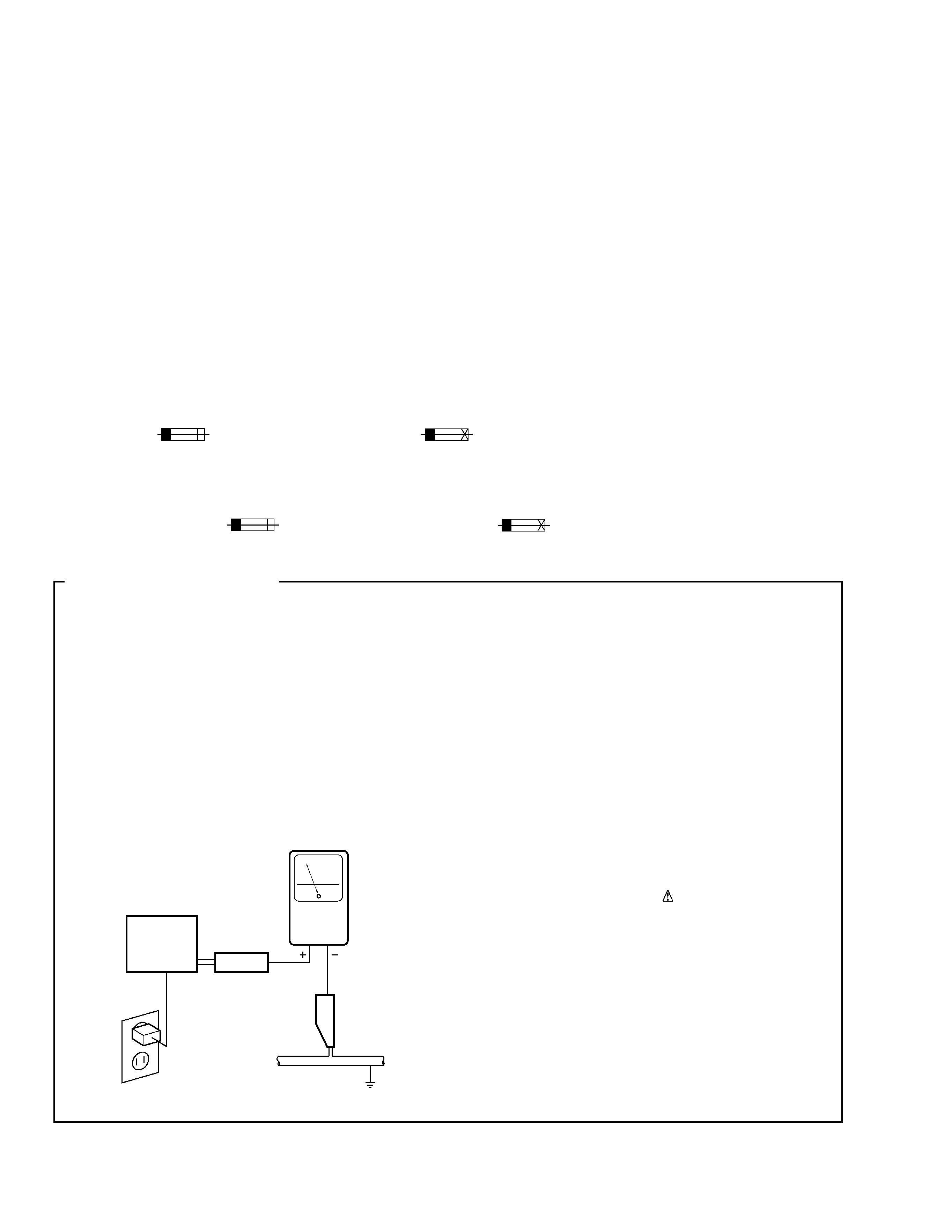
1. SAFETY PRECAUTIONS
The following check should be performed for the
continued protection of the customer and service
technician.
LEAKAGE CURRENT CHECK
Measure leakage current to a known earth ground
(water pipe, conduit, etc.) by connecting a leakage
current tester such as Simpson Model 229-2 or
equivalent between the earth ground and all exposed
metal parts of the appliance (input/output terminals,
screwheads, metal overlays, control shaft, etc.). Plug
the AC line cord of the appliance directly into a 120V
AC 60 Hz outlet and turn the AC power switch on. Any
current measured must not exceed 0.5 mA.
Device
under
test
Leakage
current
tester
Earth
ground
Reading should
not be above
0.5 mA
Also test with
plug reversed
(Using AC adapter
plug as required)
Test all
exposed metal
surfaces
AC Leakage Test
3
S-HS01
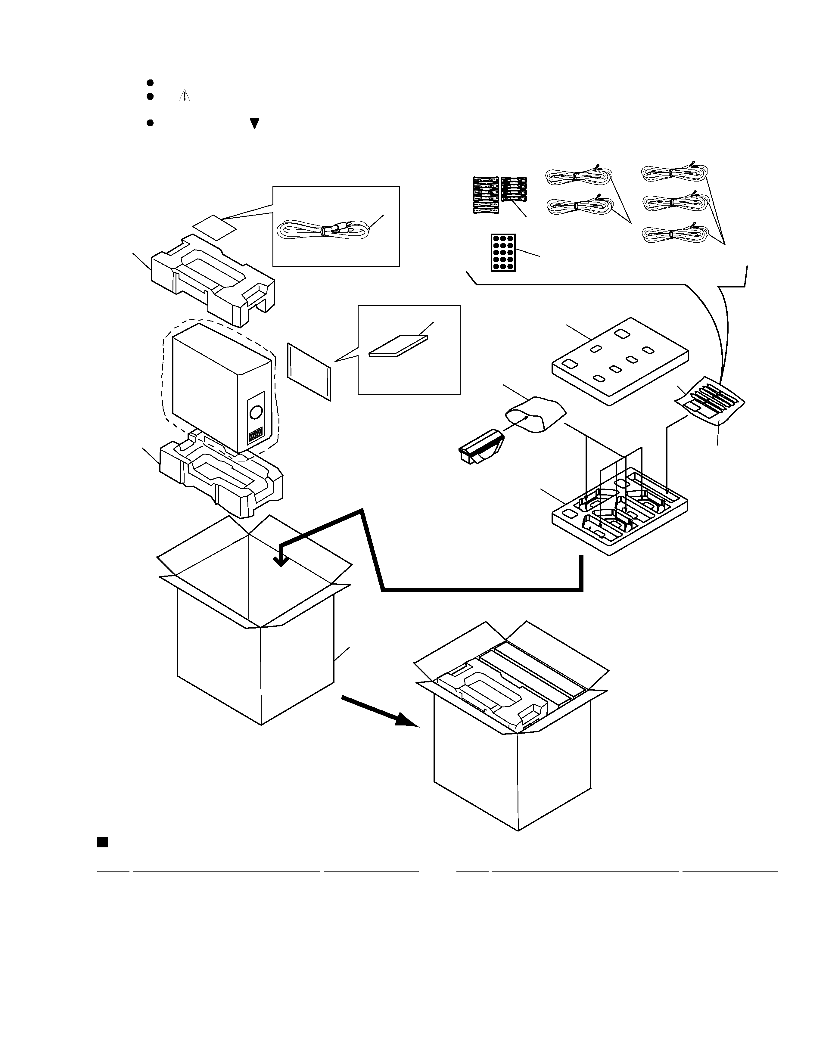
2. EXPLODED VIEWS AND PARTS LIST
Parts marked by "NSP" are generally unavailable because they are not in our Master Spare Parts List.
The
mark found on some component parts indicates the importance of the safety factor of the part.
Therefore, when replacing, be sure to use parts of identical designation.
Screws adjacent to
mark on product are used for disassembly.
NOTES:
Mark No.
Description
Part No.
Mark No.
Description
Part No.
1
RCA Plug Cord
VRC0001-A06
2
Opearting Instructions
SRD1229
(English,Chinese) (MLXTW/E type)
2
Opearting Instructions
SRD1230
(English,Chinese,Spanish) (SDBXTW/E type)
3
Protector
ITF0114C001
4
Packing Case (MLXTW/E type)
SHG2395
4
Packing Case (SDBXTW/E type) SHG2396
2.1 PACKING
PACKING PARTS LIST
NSP
5
Speaker Cord Set
SEA1573
6
Speaker Cord(Front/Center)
SDS1086
7
Speaker Cord(Rear)
SDS1087
8
Non Slip Pads
SEP1227
9
Color-coded Labels
SRW1082
NSP
10
Polyethylene Bag
SHL1251
11
Protector
SHA2327
12
Protector
SHA2329
13
Polyethylene Bag
SHL1252
3
2
3
1
7
6
8
11
10
5
13
12
9
4
4
S-HS01
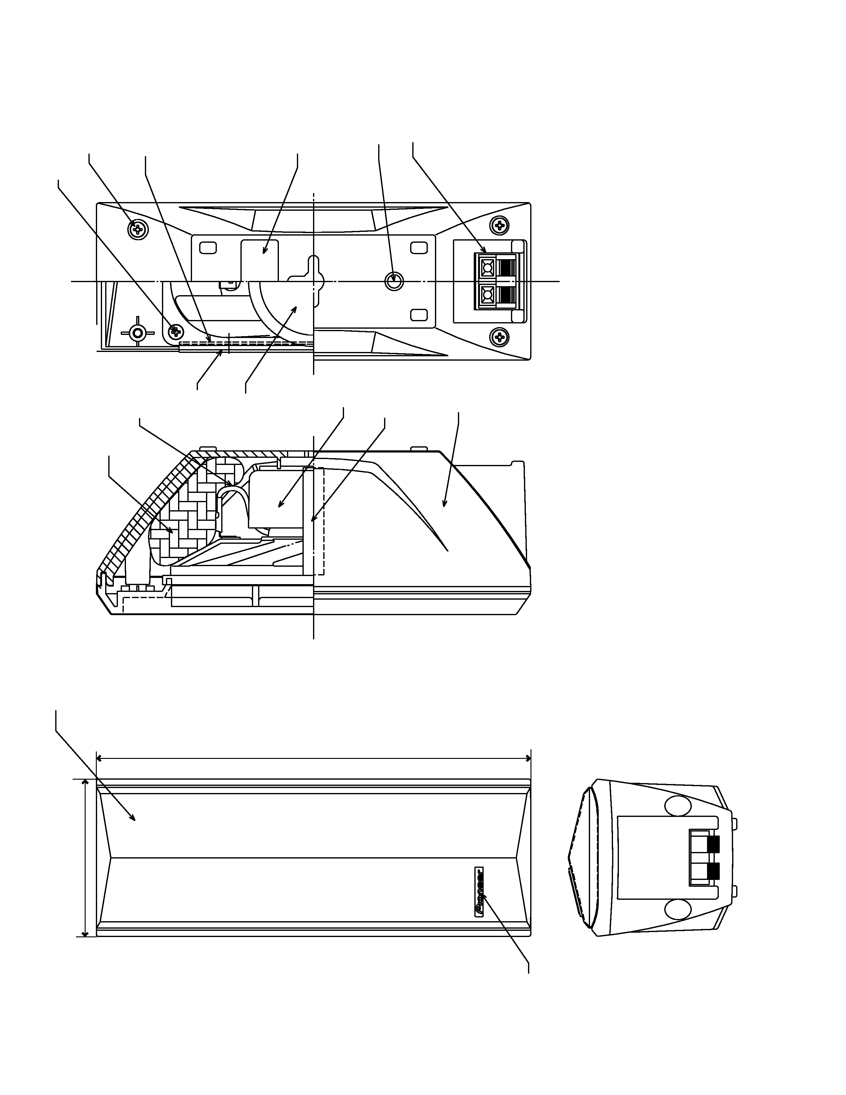
2.2 SATELLITE SPEAKER
3
16
(Rear-side
of
the
badge)
2
76
210
11
13
13
7
10
14
1
9
8
6
4
:
(+)red
5
:
(
)white
12
15
5
S-HS01
Mark No.
Description
Part No.
NSP
1
Cabinet
SNK2567
2
Grille
SMG1746
3
Logo 24
SAM1491
4
Speaker Cord (Red)
SDB1144
5
Speaker Cord (White)
SDB1145
6
Packing
SEC1571
7
Gasket
SEC1573
8
Packing
SEC1574
NSP
9
Input Terminal
SKX1076
NSP
10
Stamped Model Label
SME3269
NSP
10
Label Back
SAN3045
NSP
11
Acoustic Absorbent
SMT1137
12
Speaker
A142CU54-51F
13
Screw
PPZ40P080FZK
14
Fung Nut M5
SBN1044
15
Packing
SEC1580
NSP
16
Outside Stopper Ring
SBG1005
SATELLITE SPEAKER PARTS LIST
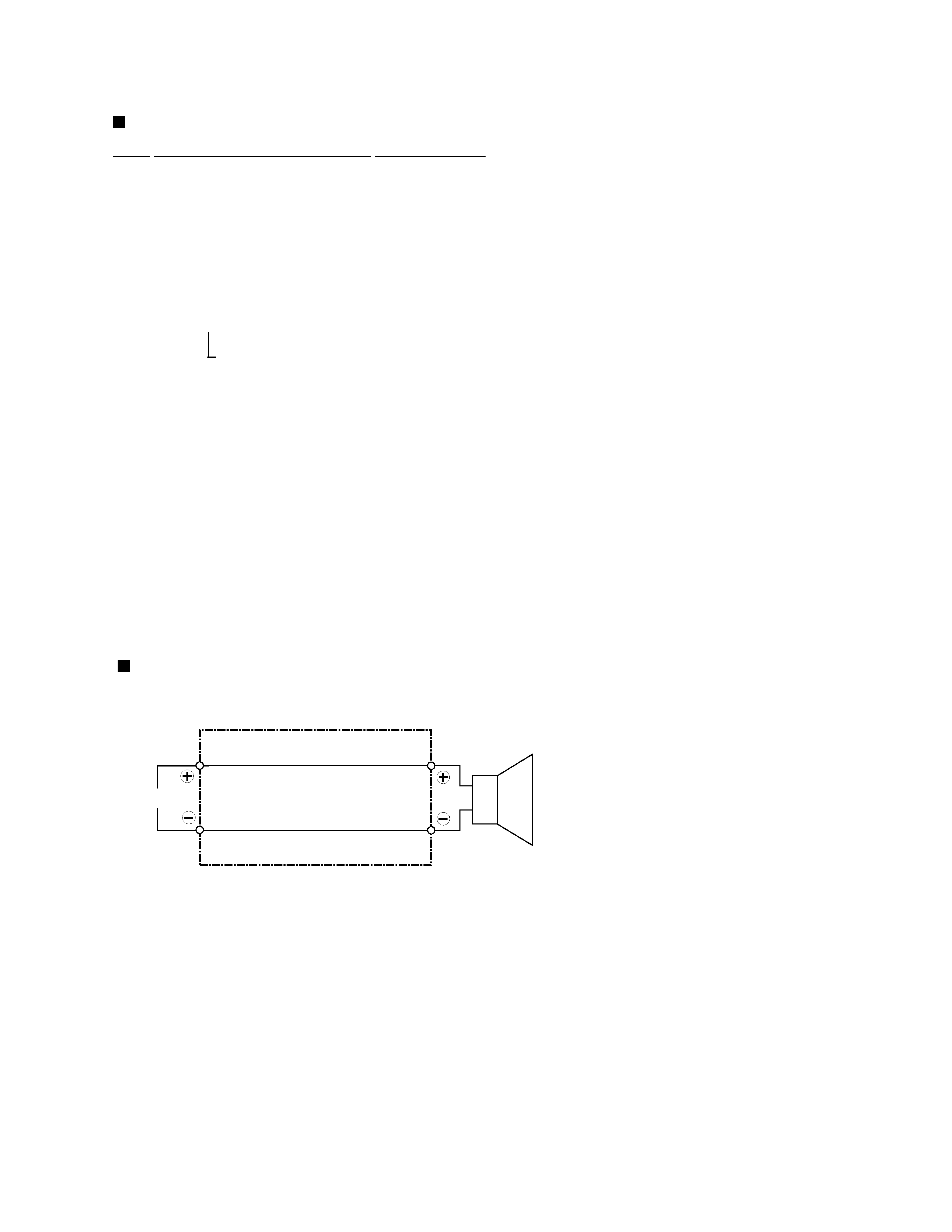
SPEAKER CORD CONNECTING DIAGRAM
Speaker Cord (SDB1144/SDB1145)
INPUT
RED
WHITE
Full-Range