ORDER NO.
PIONEER CORPORATION 4-1, Meguro 1-chome, Meguro-ku, Tokyo 153-8654, Japan
PIONEER ELECTRONICS SERVICE, INC. P.O. Box 1760, Long Beach, CA 90801-1760, U.S.A.
PIONEER EUROPE N.V. Haven 1087, Keetberglaan 1, 9120 Melsele, Belgium
PIONEER ELECTRONICS ASIACENTRE PTE. LTD. 253 Alexandra Road, #04-01, Singapore 159936
PIONEER CORPORATION 2004
SPEAKER SYSTEM
PRT-110
PFS-SDC MAY. 2004 Printed in Belgium
S-H610V
XDCN
The networks are attached to the baffle board by 4 internal screws.
To detach them, unfasten those screws.
Woofer units are attached together to the baffle board
8 external screws. To detach them, unfasten those screws.
Tweeter is attached to the baffle board
To detach it, unfasten those screws.
FOR PRECAUTION OF
REASSEMBLY AND DISASSEMBLY
The grille is attached to the baffle by its bosses and press-
fitting. To detach it, pry it open by inserting a flat blade tool
between the grille and the cabinet. Be careful not to
damage the grille or the cabinet.
Even though the suffix is different between /XDCN and /SXTW/EW5,
both models are completely same product.
S-H610V
2
NOTES :
Parts marked by "NSP" are generally unavailable because they are not in our Master Spare Parts List.
The
mark found on some component parts indicates the importance of the safety factor of the part.
Therefore, when replacing, be sure to use parts of identical designation.
PARTS LIST
Mark No.
Description
Part No.
Mark No.
Description
Part No.
Accessories
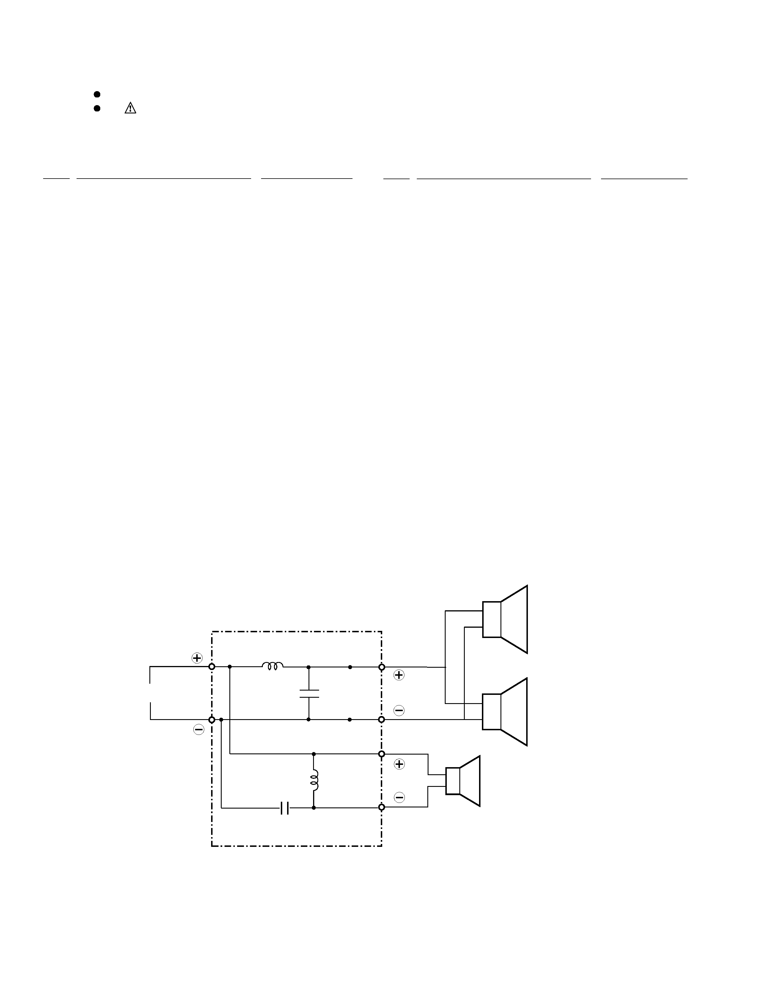
SCHEMATIC DIAGRAM
3.3
mF/250V
Tweeter
INPUT
Black
Red
Black
White
Black
White
NETWORK ASSY (FRWN-181)
1 mH
0.82 mH
m
5.6 F/250V
Woofer
Woofer
Front Panel
Red input terminal assembly
Black input terminal assembly
Screw for speaker units
Network assembly
Tweeter
Woofer
Black grille
PAV-017
FRMG-224
FRMG-223
SBA1181
FRWN-181
FADD55-53F
K77ER65-51L
FRMG-219
Instruction manual
FRRD-184