ORDER NO.
PIONEER CORPORATION 4-1, Meguro 1-Chome, Meguro-ku, Tokyo 153-8654, Japan
PIONEER ELECTRONICS SERVICE, INC. P.O. Box 1760, Long Beach, CA 90801-1760, U.S.A.
PIONEER ELECTRONIC (EUROPE) N.V. Haven 1087, Keetberglaan 1, 9120 Melsele, Belgium
PIONEER ELECTRONICS ASIACENTRE PTE. LTD. 253 Alexandra Road, #04-01, Singapore 159936
PIONEER CORPORATION 1999
SD-T50W1
PROJECTION COLOUR TELEVISION
ARP3036
OZZR JULY 1999 Printed in Japan
THIS MANUAL IS APPLICABLE TO THE FOLLOWING MODEL(S) AND TYPE(S).
Type
Model
SD-T50W1
Power Requirement
Remarks
WYZI7/2
AC220240V
This service manual should be used together with the following manual(s):
Remarks
Order No.
SD-T50W1
ARP2932
Model No.
SD-T50W1
2
1. CONTRAST OF MISCELLANEOUS PARTS
NOTES :
÷ Parts marked by " NSP " are generally unavailable because they are not in our Master Spare Parts List.
÷ The
mark found on some component parts indicates the importance of the safety factor of the part.
Therefore, when replacing, be sure to use parts of identical designation.
÷ When ordering resistors, first convert resistance values into code form as shown in the following examples.
Ex. 1
When there are 2 effective digits (any digit apart from 0), such as 560 ohm and 47k ohm (tolerance is shown by
J = 5%, and K = 10%).
560
= 56 × 101= 561 ................................................... RD1/4PU 5 6 1 J
47k
= 47 × 10 3 = 473 .................................................. RD1/4PU 4 7 3 J
0.5
= R50 ...................................................................... RN2H Â 5 0 K
1
= 1R0 ......................................................................... RS1P 1 Â 0 K
Ex. 2
When there are 3 effective digits (such as in high precision metal film resistors).
5.62k
= 562 × 10 1 = 5621 ........................................... RN1/4PC 5 6 2 1 F
÷ Parts marked by
are important parts which relate in X-rays radiation.
If any of these parts need to be replaced, always replace with specified parts.
÷ Parts marked by × are important parts which relate in X-rays radiation. If a failure occurs in any of these parts, replace the
printed circuit board assembly where the relevant part has already been adjusted as a working component. Do not replace the
actual part itself. If any part marked by
× is replaced, there is danger of being exposed to X-rays.
÷ Reference Nos. indicate the pages and Nos. in the service manual for the base model.
CONTRAST TABLE
SD-T50W1/WYZI7/2 and SD-T50W1/SL are constructed the same except for the following:
P141
CONVERGENCE ASSY
AWV1520
AWV1547
2
P162
VIDEO · UCOM ASSY
AWV1542
AWV1566
2
NSP
TUNER ASSY
AWV1543
AWV1589
P143
TUNER ASSY
AWZ6075
AWZ6155
2
P144
R CONV DAC ASSY
AWZ6076
AWZ6076
P145
G CONV DAC ASSY
AWZ6077
AWZ6077
P146
B CONV DAC ASSY
AWZ6078
AWZ6078
P167
A CONNECTOR ASSY
AWZ6079
AWZ6079
P168
B CONNECTOR ASSY
AWZ6080
AWZ6080
P149
C CONNECTOR ASSY
AWZ6081
AWZ6081
NSP
AV I/O ASSY
AWV1544
AWV1567
P1610
AV I/O ASSY
AWZ6082
AWZ6121
2
P1511
FRONT CONTROL ASSY
AWZ6083
AWZ6122
P1612
AV2 ASSY
AWZ6084
AWZ6084
P1413
S TERMINAL ASSY
AWZ6085
AWZ6085
NSP
CRT DRIVE ASSY
AWV1545
AWV1781
P1614
AUDIO ASSY
AWZ6086
AWZ6123
2
P1715
R CRT DRIVE ASSY
AWZ6087
AWZ6087
P1716
G CRT DRIVE ASSY
AWZ6088
AWZ6088
P1717
B CRT DRIVE ASSY
AWZ6089
AWZ6089
P1418
AC IN ASSY
AWZ6090
AWZ6420
P1619
Y/C ASSY
AWZ6091
AWZ6091
P1620
D CONNECTOR ASSY
AWZ6092
AWZ6092
P1421
POWER DOWN ASSY
AWZ6093
AWZ6093
P1422
RELAY DRIVE ASSY
AWZ6094
AWZ6094
P1623
POWER SUPPLY ASSY
AWV1546
AWV1767
2
P1624
DIGITAL ASSY
AWV1659
AWV1659
TV FRONT END
AXF1085
AXF1085
RELAY ASSY
Not used
AWV1768
1 No. 1, 2
Ref.
No.
Remarks
SD-T50W1
SD-T50W1
SL
WYZI7/2
Part No.
Mark
Symbol and Description
*1: The numbers in the remarks column correspond to the numbers on the " EXPLODED VIEWS ".
*2: Refer to " 2. SCHEMATIC DIAGRAM ".
SD-T50W1
3
PACKING
P8-152
Operating Instructions (English)
ARB1500
Not used
Operating Instructions
Not used
ARC1500
(Dutch/Swedish/Spanish/Portuguese)
Operating Instructions
Not used
ARE1342
(English/French/German/Italian)
P8-155
NSP
Caution Label 220V
ARR1002
Not used
P8-156
NSP
Warranty Card
ARW1020
ARY7022
P8-158
Remote Control Unit
AXD1424
AXD1440
(CU-SD097)
(CU-SD106)
P8-160
NSP
Battery (R03, AAA)
AEX021
DCX1023
P8-165
Upper Carton
AHD2846
AHD3010
NSP
Caution Card
Not used
AAX1756
NSP
Conver Caution
Not used
ARM1113
NSP
X-Rays Approval S
Not used
ARY1082
NSP
Schematic Diagram 1
Not used
ARH1164
NSP
Schematic Diagram 2
Not used
ARH1165
NSP
Schematic Diagram 3
Not used
ARH1166
NSP
Adjustment
Not used
ARH1157
NSP
Caution Card
Not used
ARM1065
FRONT VIEW
P9-145
Badge
AAM1068
AAM1083
REAR VIEW
P13-45
AC Power Cord
ADG1109
Not used
P13-97
Spacer
AEC1594
Not used
P14-57
3P Lead Wire with Housing (J10)
ADX2244
ADX2273
GRILLE AND CONTROL PANEL
P15-26
Control Panel
AMB2524
AMB2646
P15-58
Wire Harness C (J11)
ADX2245
ADX2538
P15-143
Control Sheet
AAK2668
AAK2734
CHASSIS SECTION
P16-34
Voltage Selector (S1)
AKX7001
Not used
P16-56
Wire Harness B (J19)
ADX2243
ADX2269
P16-70
Rear Panel
ANC2276
ANC2325
OTHERS
Cabinet 50 (WOOD)
AMM2604
AMM2712
Plug Cord (J20)
ADE082
ADE1157
2P Lead Wire with Housing (J12)
ADX2246
Not used
3P Lead Wire with Housing (J12)
Not used
ADX2537
2
Cut Wire (J14)
ADX2248
Not used
Cut Wire (J15)
ADX2249
Not used
Cut Wire (J16)
ADX2250
Not used
Cut Wire (J17)
ADX2251
Not used
Choke Coil (L4)
Not used
ATL1128
1 No. 2, 2
Ferrite Core (L5, L6)
Not used
ATX1019
1 No. 3, 2
Block Core (L7)
Not used
ATX1030
1 No. 4, 2
Holder
Not used
ANG2130
1 No. 5
Fixed Mold
Not used
AEC1600
1 No. 6
CU Packing Case (for AC power cord)
Not used
AHC1029
1 No. 7
NSP
Release Tie
Not used
AEC1723
1 No. 8
NSP
CR Holder
Not used
ANG1867
1 No. 9
PVC Sheet
Not used
AEC1792
for Mirror Case
Screw (for Bottom Rail)
Not used
BYC40P200FZK
Ref.
No.
Remarks
SD-T50W1
SD-T50W1
SL
WYZI7/2
Part No.
Mark
Symbol and Description
*1: The numbers in the remarks column correspond to the numbers on the " EXPLODED VIEWS ".
*2: Refer to " 2. SCHEMATIC DIAGRAM ".
SD-T50W1
4
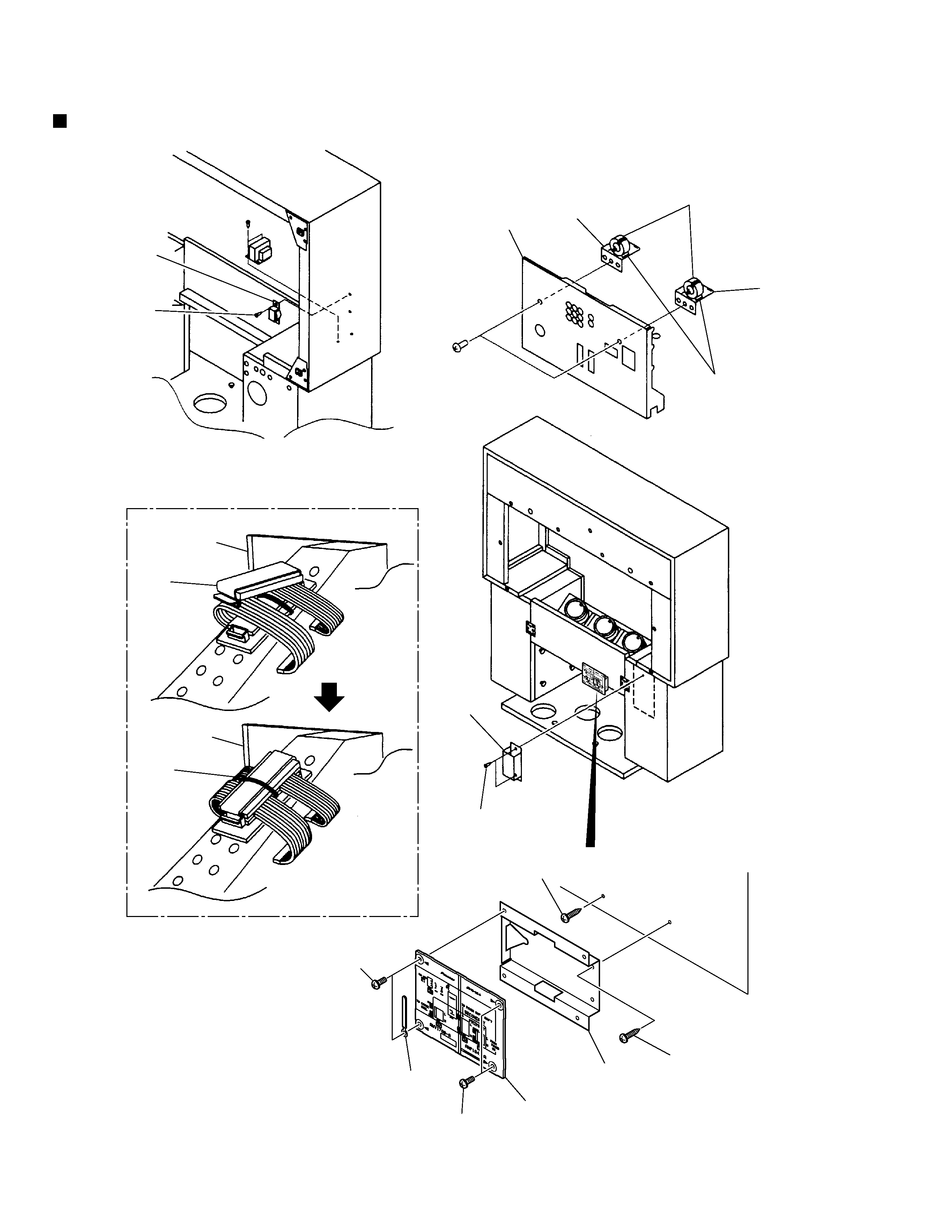
Rear Panel
Rear Panel
4
6
5
5
2
Screw
(BYC40P160FMC)
3
8
7
Screw (ABA1020)
Screw
(ABA1198)
Screw
(BYC40P120FZK)
Screw
(BBZ30P080FZK)
1
9
Screw
(BBZ30P080FZK)
Binder
(AEP-215)
Rear Cover
Rear Panel
EXPLODED VIEWS
SD-T50W1
5
VIDEO BLOCK
C1184C1186
Not used
CKDYB102K50
C1187
Not used
CCDSL221J50
C1188
Not used
CKDYF103Z50
C1189
Not used
CKDYB222K50
C1190
Not used
CCDSL470J50
UCOM BLOCK
C3348, C3349
Not used
CKDYF103Z50
R3482
Not used
RD1/4PU103J
R3483
RD1/4PU103J
Not used
AV I/O BLOCK
D1825, D1826, D1828, D1829, D1831,
HSS104-02
Not used
D1832
D1827, D1830
MTZJ12
Not used
C1867, C1868
CEAS4R7M50
Not used
C1869, C1870
CEAS220M50
Not used
C1871
CKCYF103Z50
Not used
C1884, C1885
Not used
CCDSL560J50
CN1811
Plug 10-P
KM250MA10
Not used
TELETEXT BLOCK
R2052
Not used
RD1/4PU101J
AWV1566 and AWV1542 are constructed the same except for the following:
Mark
Remarks
Symbol and Description
Part No.
AWV1542
AWV1566
VIDEO · UCOM ASSY
CONTRAST OF PCB ASSEMBLIES
AWZ6121 and AWZ6082 are constructed the same except for the following:
Mark
Remarks
Symbol and Description
Part No.
AWZ6082
AWZ6121
AV I/O ASSY
Q3901, Q3902
2SC2458
Not used
D3901, D3902
MTZJ15
Not used
C3902, C3903
CEAS4R7M50
Not used
C3905
CKCYF473Z50
Not used
C3906
CEAS470M25
Not used
R3901, R3902
RD1/4PU474J
Not used
R3903R3905
RD1/4PU750J
Not used
R3906R3909
RD1/4PU473J
Not used
R3910, R3911
RD1/4PU102J
Not used
R3913, R3914
RD1/4PU472J
Not used
CN3902
Pin Jack (1P)
AKB1063
Not used
CN3903
Pin Jack (1P)
AKB1062
Not used
CN3904
Pin Jack (1P)
AKB1064
Not used
CN3901
Socket
AKP1081
Not used
CN3905
Plug 10-P
KM250MA10
Not used
AWZ6122 and AWZ6083 are constructed the same except for the following:
Mark
Remarks
Symbol and Description
Part No.
AWZ6083
AWZ6122
FRONT CONTROL ASSY
: Refer to " 2. SCHEMATIC DIAGRAM ".
: Refer to " 2. SCHEMATIC DIAGRAM ".