
1
CS-G405-K/Q
Service
Manual
ORDER NO.
PET99013
PIONEER CORPORATION 4-1, Meguro 1-Chome, Meguro-ku, Tokyo 153-8654, Japan
PIONEER ELECTRONICS SERVICE, INC. P.O. Box 1760, Long Beach, CA 90801-1760, U.S.A.
PIONEER ELECTRONIC (EUROPE) N.V. Haven 1087, Keetberglaan 1 B-9120 Melsele, Belgium
PIONEER ELECTRONICS ASIACENTRE PTE. LTD. 501 Orchard Road, #10-00, Wheelock Place, Singapore 238880
©PIONEER CORPORATION 1999
1999 Printed in U.S.A.
HOW TO REASSEMBLE AND
DISASSEMBLE
65S
This service manual is intended for qualified service technicians; it is
not meant for the casual do-it- your selfer. Qualified technicians have
the necessary test equipment and tools, and have been trained to
properly and safely repair complex products such as those covered by
this manual.
Improperly performed repairs can adversely affect the safety and
reliability of the product and may void the warranty. If you are not
qualified to perform the repair of this product properly and safely, you
should not risk trying to do so and refer the repair to a qualified service
technician.
SPEAKER SYSTEM
S-DF2-K
·
The grille is attached to the trim baffle. Detach it by pulling the
grille towards you.
·
The trim baffle is attached to the baffle by external screws. To
detach it, unfasten those screws.
·
The woofer is attached to the trim baffle by internal screws. To
detach it, unfasten those screws. When attaching, face its terminal
downward.
·
The tweeter is attached to the baffle by internal screws. To detach
it, unfasten those screws.
·
The terminal cup is attached to the backboard by external screws.
To detach it, unfasten those screws.
·
The crossover assembly is attached to the terminal cup with
adhesive. To detach it, first remove terminal cup, and then remove it.
2
CS-G405-K/Q
PARTS LIST
NOTES: · Parts marked by "NSP" are generally unavailable because they are not in our Master Spare Parts List.
· The "
"mark found on some component parts indicates the importance of the safety factor of the part.
Therefore, when replacing, be sure to use parts of identical designation.
Mark No. Description
Parts No.
Mark No. Description
Parts No.
For Packing
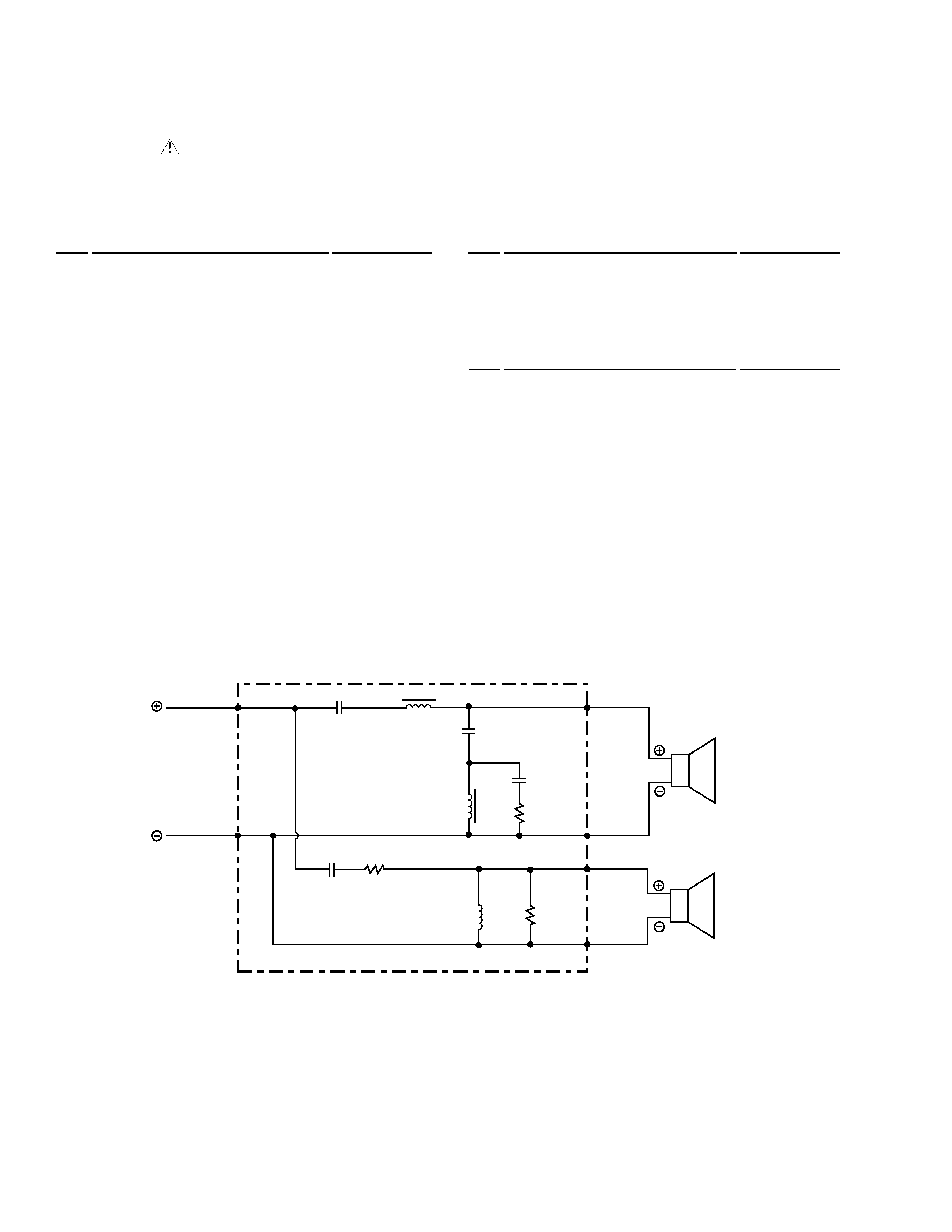
SCHEMATIC DIAGRAM
S-DF2-K
Low Frequency Transducer
267590
High Frequency Transducer
267481
Grille Assembly
268553
Trim Baffle
267585
Catch Cup
270457
Transducer Clamp
268300
Crossover Assembly
268820
Gasket for Terminal Cup
268840
Instruction Manual
267416
Poly Bag
264244
Packing Case
267525
Foam pad
267530
Screw (for Low Frequency Trans)
BPZ40P200FZB
Screw (for High Frequency Trans)
BBZ35P140FMC
Screw (for Trim Baffle)
BYC40P200FZB
Screw (for Terminal Cup)
BYC40P200FZB
Mark No. Description
Parts No.
INPUT
WHITE
25.0
µ F / 50 V
40.0
µ F / 50 V
5.0
µ F / 50 V
4.0 / 5w
3.0 / 5w
15 / 5w
0.80 mH
1.10 mH
0.14 mH
RED
BLK
BLU
BRN
TWEETER
WOOFER
WHITE/BLACK
600.0
µ F / 50 V