
file:///C|/Documents%20and%20Settings/bob/My%20Documents/manualdirectory.htm
This file was downloaded and provided FREE OF CHARGE
from the ManualDirectory community.
You can find many free to download Service Manuals & Schematics at
http://www.manualdirectory.co.uk
file:///C|/Documents%20and%20Settings/bob/My%20Documents/manualdirectory.htm01/04/2007 01:34:00
ORDER NO.
PIONEER CORPORATION 4-1, Meguro 1-chome, Meguro-ku, Tokyo 153-8654, Japan
PIONEER ELECTRONICS SERVICE, INC. P.O. Box 1760, Long Beach, CA 90801-1760, U.S.A.
PIONEER EUROPE N.V. Haven 1087, Keetberglaan 1, 9120 Melsele, Belgium
PIONEER ELECTRONICS ASIACENTRE PTE. LTD. 253 Alexandra Road, #04-01, Singapore 159936
PIONEER CORPORATION 2000
Model
PDA-4003
DOWN CONVERTER
ARP3046
T- ZZB MAR. 2000 Printed in Japan
1. SAFETY INFORMATION .................................... 2
2. EXPLODED VIEWS AND PARTS LIST ............. 3
3. BLOCK DIAGRAM AND SCHEMATIC DIAGRAM
......................................................... 5
4. PCB CONNECTION DIAGRAM ....................... 14
5. PCB PARTS LIST ............................................. 18
6. ADJUSTMENT .................................................. 20
CONTENTS
7. GENERAL INFORMATION .............................. 21
7.1 IC ................................................................ 21
8. PANEL FACILITIES AND SPECIFICATIONS
.................................................................... 22
THIS MANUAL IS APPLICABLE TO THE FOLLOWING MODEL(S) AND TYPE(S).
Remarks
Power Requirement
Type
PDA-4003
UCBWYVLDK
PDA-4003
2
1. SAFETY INFORMATION
1. SAFETY PRECAUTIONS
The following check should be performed for the
continued protection of the customer and service
technician.
ANY MEASUREMENTS NOT WITHIN THE LIMITS
OUTLINED ABOVE ARE INDICATIVE OF A PO-
TENTIAL SHOCK HAZARD AND MUST BE COR-
RECTED BEFORE RETURNING THE APPLIANCE
TO THE CUSTOMER.
2. PRODUCT SAFETY NOTICE
Many electrical and mechanical parts in the appli-
ance have special safety related characteristics. These
are often not evident from visual inspection nor the
protection afforded by them necessarily can be ob-
tained by using replacement components rated for
voltage, wattage , etc.
Replacement parts which have
these special safety
characteristics are identified in
this Service Manual.
Electrical components having such features are
identified by marking with a
on the schematics and
on the parts list in this Service Manual.
The use of a substitute replacement component which
does not have the same safety characteristics as the
PIONEER recommended replacement one, shown in
the parts list in this Service Manual, may create shock,
fire, or other hazards.
Product Safety is continuously under review and
new instructions are issued from time to time. For
the latest information, always consult the current
PIONEER Service Manual. A subscription to, or
ad-
ditional copies of, PIONEER Service Manual may be
obtained at a nominal charge from PIONEER.
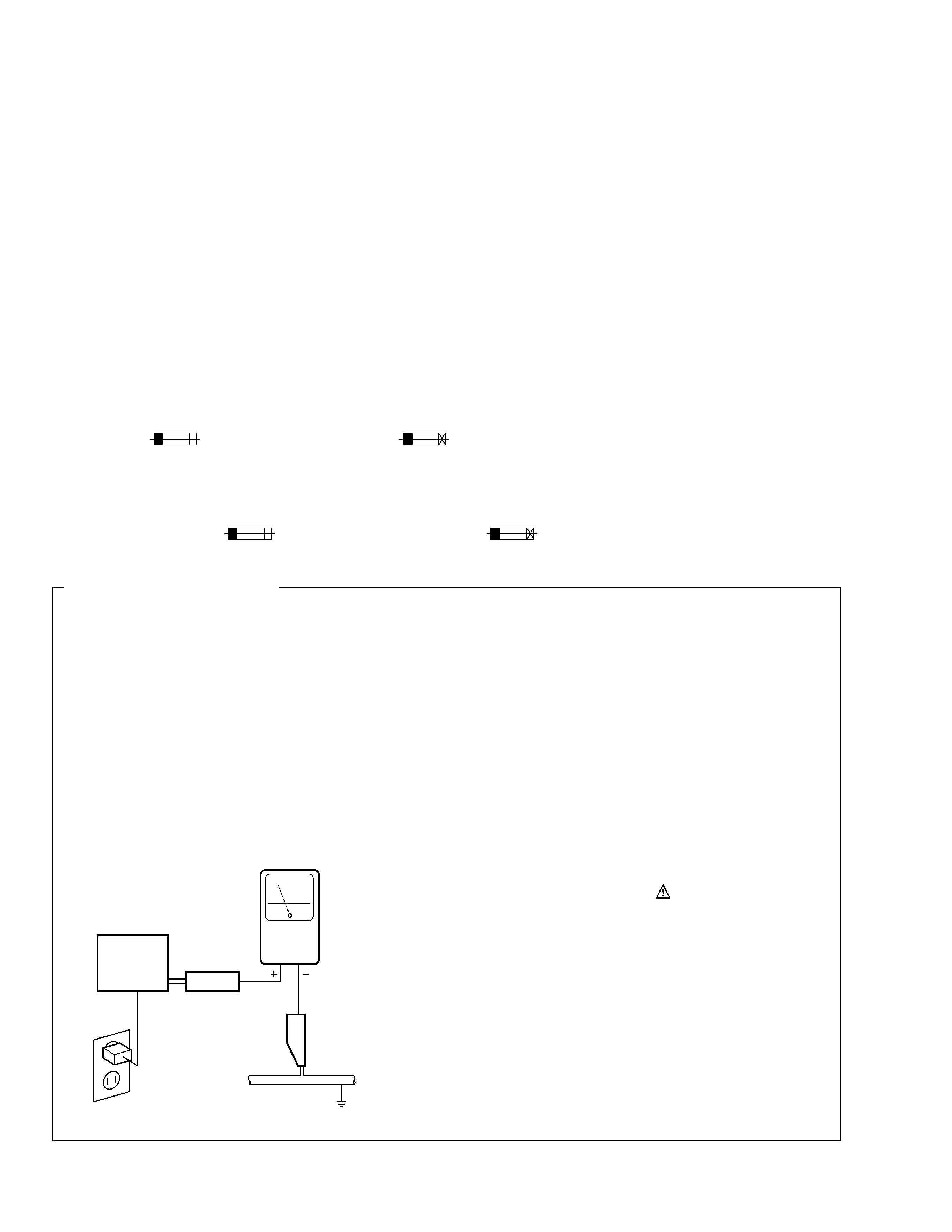
LEAKAGE CURRENT CHECK
Measure leakage current to a known earth ground
(water pipe, conduit, etc.) by connecting a leakage
current tester such as Simpson Model 229-2 or
equivalent between the earth ground and all exposed
metal parts of the appliance (input/output terminals,
screwheads, metal overlays, control shaft, etc.). Plug
the AC line cord of the appliance directly into a 120V
AC 60 Hz outlet and turn the AC power switch on. Any
current measured must not exceed 0.5 mA.
(FOR USA MODEL ONLY)
Also test with plug
reversed
(Using AC adapter
plug as required)
Device
under
test
Test all exposed
metal surfaces
Earth ground
Leakage
current
tester
Reading should
not be above
0.5 mA
AC Leakage Test
REMARQUE
(POUR MODÈLE CANADIEN SEULEMENT)
Les symboles de fusible
(fusible de type rapide) et/ou
(fusible de type lent) sur CCI indiquent que les
pièces de remplacement doivent avoir la même désignation.
NOTICE
(FOR CANADIAN MODEL ONLY)
Fuse symbols
(fast operating fuse) and/or
(slow operating fuse) on PCB indicate that replacement parts
must be of identical designation.
This service manual is intended for qualified service technicians; it is not meant for the casual
do-it-yourselfer. Qualified technicians have the necessary test equipment and tools, and have been
trained to properly and safely repair complex products such as those covered by this manual.
Improperly performed repairs can adversely affect the safety and reliability of the product and may
void the warranty. If you are not qualified to perform the repair of this product properly and safely, you
should not risk trying to do so and refer the repair to a qualified service technician.
WARNING
This product contains lead in solder and certain electrical parts contain chemicals which are known to the state of California to
cause cancer, bir th defects or other reproductive harm.
Health & Safety Cod e Section 25249.6 Proposition 65
PDA-4003
3
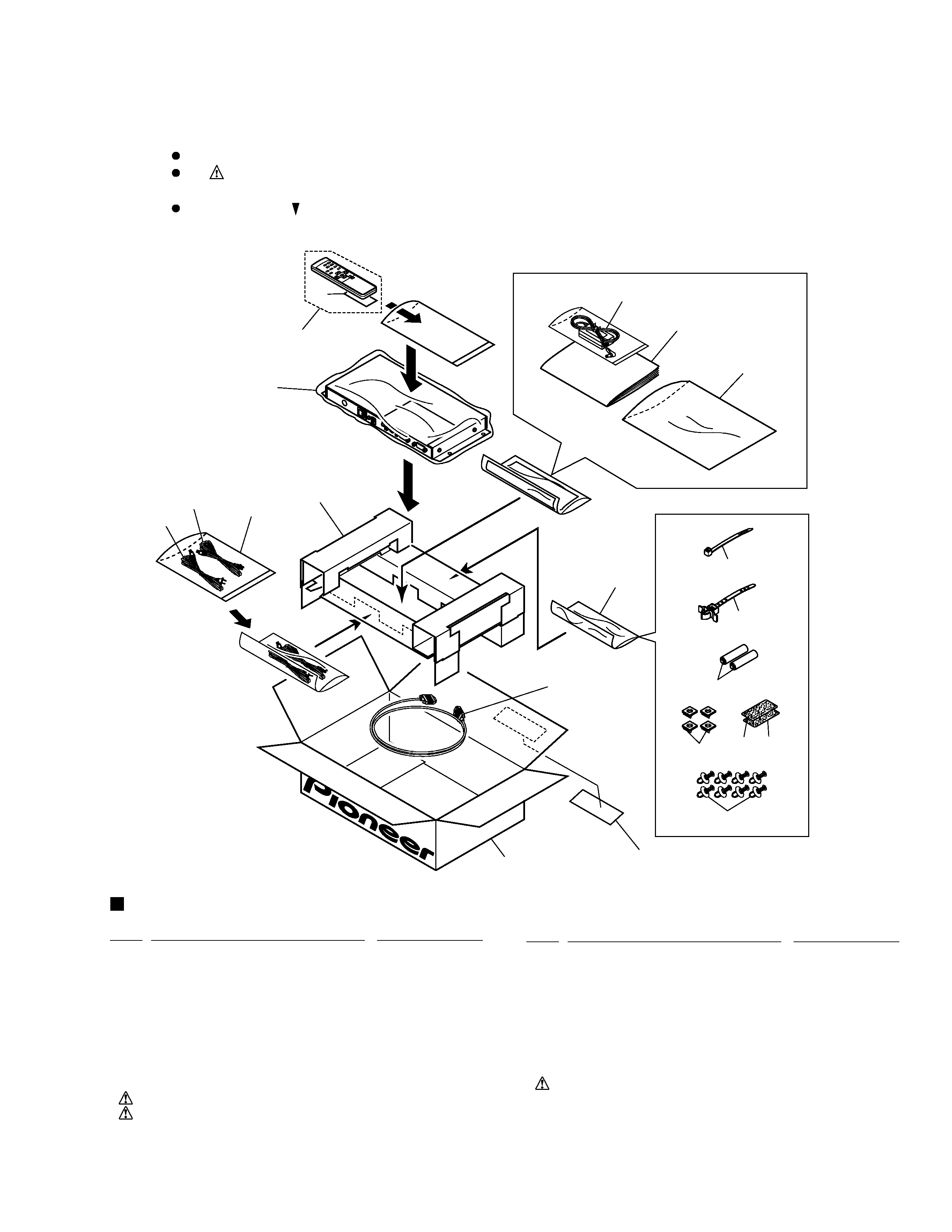
2.1 PACKING
1
Packing Case
AHD3054
2
Card Board
AHB1219
3
Packing Sheet
AHG1300
4
Operating Instructions
ARD1035
(Japanese/English/French/ German/
Italian/Dutch/Spanish)
5
Remote Control Unit (CU-V161) AXD1450
6
D-Sub 15pin Cable
ADF1010
7
AC Power Cord
ADG1034
8
AC Power Cord
RDG1127
9
Rubber Cushion
AEB1361
10
Binder
AEC093
PACKING PARTS LIST
2. EXPLODED VIEWS AND PARTS LIST
NSP
11
Cable Strap
AEC906
12
Screw Rivet
AEC1855
13
Magic Tape A
AEH1032
14
Magic Tape B
AEH1033
NSP
15
Dry Cell Battery (AA/R6P)
AEX1025
NSP
16
Literature Bag
AHG117
NSP
17
Packing Bag
AHG1162
18
AC Adaptor
AXY1048
19
Battery Cover
AZN2098
20
EMC Caution Label
AAX2708
NSP
21
Literature Bag
AHG1083
16
7
8
10 (
×10)
4
20
21
18
3
5
19
2
6
1
11
15
14
13
12
9
17
NOTES :
Parts marked by " NSP " are generally unavailable because they are not in our Master Spare Parts List.
The
mark found on some component parts indicates the importance of the safety factor of the part.
Therefore, when replacing, be sure to use parts of identical designation.
Screws adjacent to
mark on the product are used for disassembly.
Mark No.
Description
Part No.
Mark No.
Description
Part No.
PDA-4003
4
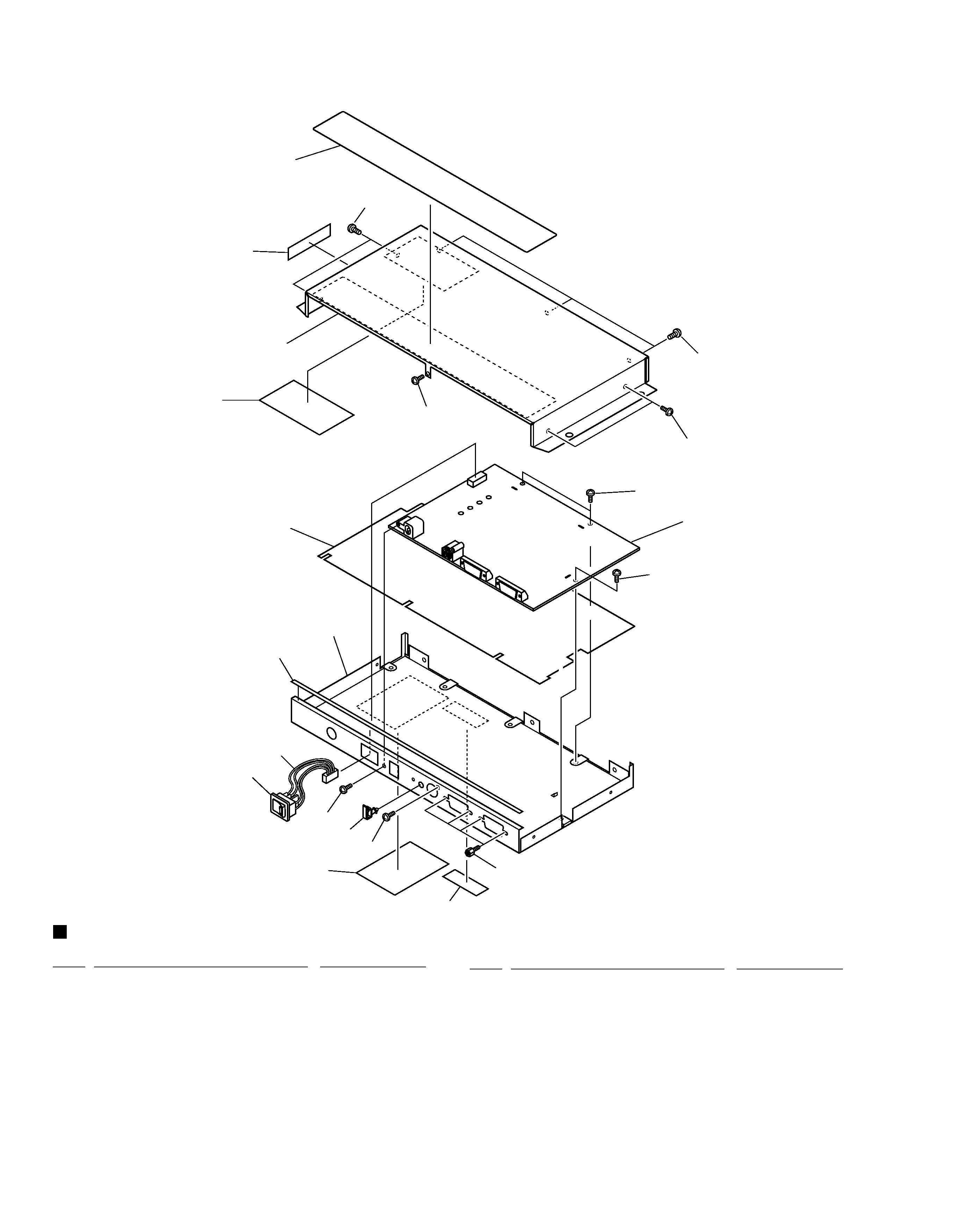
2.2 EXTERIOR
1
DOWN CONVERTER ASSY
AWV1823
2
Power Switch
BSM1002
3
5P Housing Wire
ADX2570
4
Chassis
ANA1624
5
Insulating Sheet
AEC1843
6
Locking Mini Clamp
AEC1854
NSP
7
Name Label
AAL2319
8
Serial Sheet
AAX2609
9
Solder Warning Label
AAX2644
10
Shield Gasket L
ANK1652
EXTERIOR PARTS LIST
11
Label
AAX2750
NSP
12
Label
VRW1629
13
Hexagon Head Screw
BBA1051
14
Screw
BBZ30P050FZK
15
Screw
BMZ30P060FZK
16
Screw
BPZ30P080FZK
17
Metal Bonnet
ANE1586
1
5
4
10
15
13
7
12
14
17
9
14
8
11
14
14
14
14
16
6
2
3
Mark No.
Description
Part No.
Mark No.
Description
Part No.