ORDER NO.
Service
Manual
PIONEER ELECTRONIC CORPORATION
4-1, Meguro 1-Chome, Meguro-ku, Tokyo 153-8654, Japan
PIONEER ELECTRONICS SERVICE, INC. P.O. Box 1760, Long Beach, CA 90801-1760, U.S.A.
PIONEER ELECTRONIC (EUROPE) N.V . Haven 1087, Keetberglaan 1, 9120 Melsele, Belgium
PIONEER ELECTRONICS ASIACENTRE PTE. LTD. 501 Orchard Road, #10-00 Lane Crawford Place, Singapore 0923
C
C
C
C
C PIONEER ELECTRONIC CORPORATION 1998
RRV1915
T-ZZR FEB.1998 Printed in Japan
PCP-PR24
PORTABLE CD-ROM DRIVE
THIS MANUAL IS APPLICABLE TO THE FOLLOWING MODEL(S) AND TYPE(S).
Type
Model
PCP-PR24
Power Requirement
Remarks
KU
DC power supply
CONTENTS
1. SAFETY INFORMATION .................................... 2
2. EXPLODED VIEWS AND PARTS LIST ............. 3
3. SCHEMATIC DIAGRAM ..................................... 7
4. PCB CONNECTION DIAGRAM ....................... 16
5. PCB PARTS LIST ............................................. 18
6. ADJUSTMENT .................................................. 20
7. GENERAL INFORMATION .............................. 26
7.1 PARTS ....................................................... 26
7.1.1 IC ............................................................. 26
7.1.2 DISPLAY .................................................. 32
7.2 BLOCK DIAGRAM ....................................... 32
8. PANEL FACILITIES AND SPECIFICATIONS
................................................................... 33
PCP-PR24
2
1. SAFETY INFORMATION
1. SAFETY PRECAUTIONS
The following check should be performed for the
continued protection of the customer and service
technician.
ANY MEASUREMENTS NOT WITHIN THE LIMITS
OUTLINED ABOVE ARE INDICATIVE OF A PO-
TENTIAL SHOCK HAZARD AND MUST BE COR-
RECTED BEFORE RETURNING THE APPLIANCE
TO THE CUSTOMER.
2. PRODUCT SAFETY NOTICE
Many electrical and mechanical parts in the appli-
ance have special safety related characteristics. These
are often not evident from visual inspection nor the
protection afforded by them necessarily can be ob-
tained by using replacement components rated for
voltage, wattage , etc.
Replacement parts which have
these special safety
characteristics are identified in
this Service Manual.
Electrical components having such features are
identified by marking with a
on the schematics and
on the parts list in this Service Manual.
The use of a substitute replacement component which
does not have the same safety characteristics as the
PIONEER recommended replacement one, shown in
the parts list in this Service Manual, may create shock,
fire, or other hazards.
Product Safety is continuously under review and
new instructions are issued from time to time. For
the latest information, always consult the current
PIONEER Service Manual. A subscription to, or
ad-
ditional copies of, PIONEER Service Manual may be
obtained at a nominal charge from PIONEER.
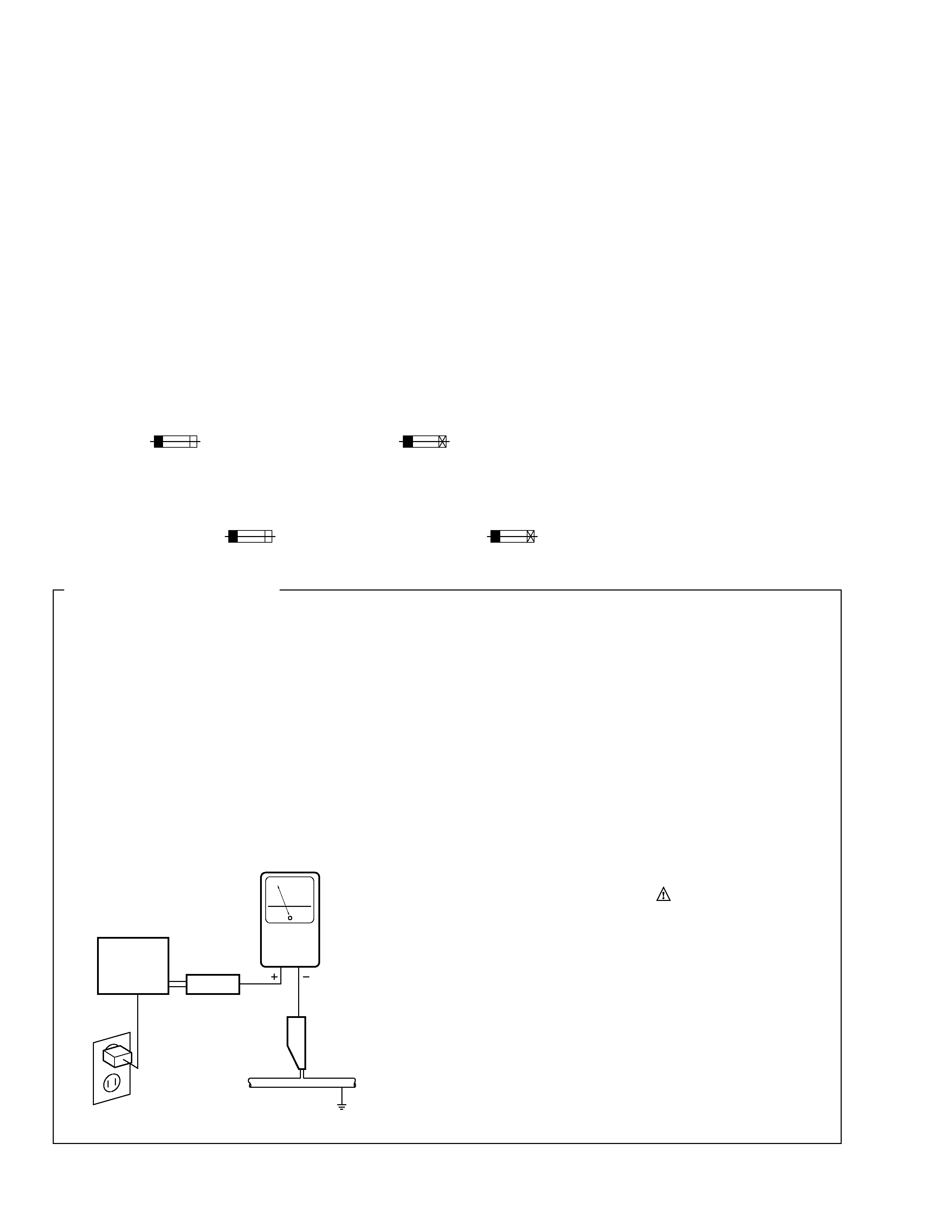
LEAKAGE CURRENT CHECK
Measure leakage current to a known earth ground
(water pipe, conduit, etc.) by connecting a leakage
current tester such as Simpson Model 229-2 or
equivalent between the earth ground and all exposed
metal parts of the appliance (input/output terminals,
screwheads, metal overlays, control shaft, etc.). Plug
the AC line cord of the appliance directly into a 120V
AC 60 Hz outlet and turn the AC power switch on. Any
current measured must not exceed 0.5 mA.
(FOR USA MODEL ONLY)
Also test with plug
reversed
(Using AC adapter
plug as required)
Device
under
test
Test all exposed
metal surfaces
Earth ground
Leakage
current
tester
Reading should
not be above
0.5 mA
AC Leakage Test
This service manual is intended for qualified service technicians; it is not meant for the casual
do-it-yourselfer. Qualified technicians have the necessary test equipment and tools, and have been
trained to properly and safely repair complex products such as those covered by this manual.
Improperly performed repairs can adversely affect the safety and reliability of the product and may
void the warranty. If you are not qualified to perform the repair of this product properly and safely, you
should not risk trying to do so and refer the repair to a qualified service technician.
WARNING
Lead in solder used in this product is listed by the California Health and Welfare agency as a known reproductive toxicant which
may cause birth defects or other reproductive harm (California Health & Safety Code, Section 25249.5).
When servicing or handling circuit boards and other components which contain lead in solder, avoid unprotected skin contact with
the solder. Also, when soldering do not inhale any smoke or fumes produced.
REMARQUE
(POUR MODÈLE CANADIEN SEULEMENT)
Les symboles de fusible
(fusible de type rapide) et/ou
(fusible de type lent) sur CCI indiquent que les
pièces de remplacement doivent avoir la même désignation.
NOTICE
(FOR CANADIAN MODEL ONLY)
Fuse symbols
(fast operating fuse) and/or
(slow operating fuse) on PCB indicate that replacement parts
must be of identical designation.
PCP-PR24
3
2. EXPLOLDED VIEWS AND PARTS LIST
NOTES :
÷ Parts marked by " NSP " are generally unavailable because they are not in our Master Spare Parts List.
÷ The
mark found on some component parts indicates the importance of the safety factor of the part.
Therefore, when replacing, be sure to use parts of identical designation.
÷ Screw adjacent to
mark on the product are used for disassembly.
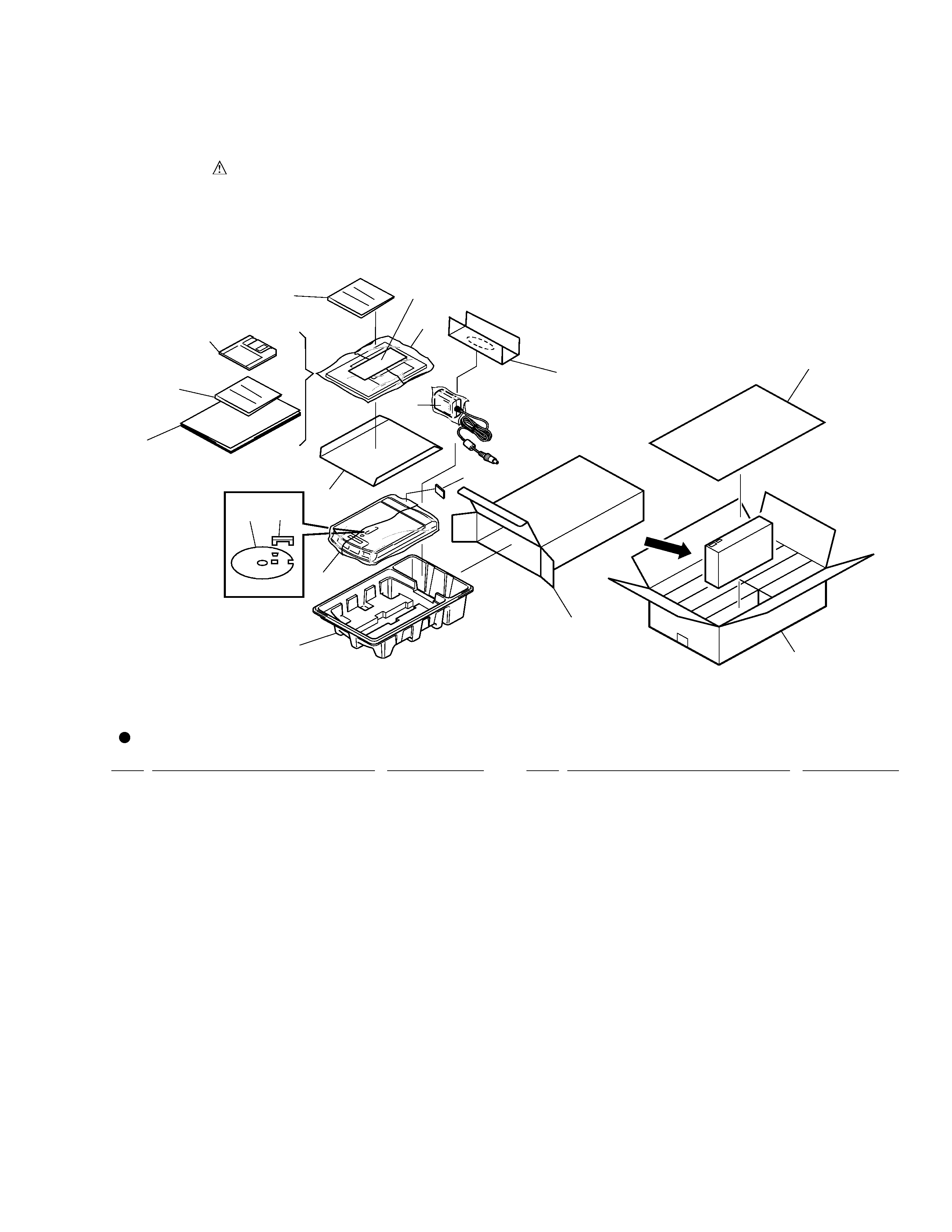
2.1 PACKING
Mark No.
Description
Parts No.
1
MIRROR MAT SHEET
DHL1050
(400 X 550 X 0.5 )
2
PARTITION
QHA1029
3
PARTITION PLATE(590X370)
QHA1026
4
TRAY
QHA1028
5
PACKING CASE
QHG1049
6
MASTER CARTON
QHG1050
7
POLYETHYLENE BAG
Z21-038
(230 X 340 X 0.03 )
8
PARTITION S
QHA1030
NSP
9
SILICA GEL (2g)
QEN1002
Mark No.
Description
Parts No.
10
OPERATING INSTRUCTIONS
QRB1004
(English)
NSP
11
WARRANTY CARD
QRY1002
12
AC ADAPTOR
QWX1067
13
SETUP DISK
QWX1070
14
TRANSPORT PAD
QHA1021
15
TRANSPORT SPACER
QEE1001
16
LICENCE AGREEMENT CARD
QRM1007
NSP
17
PACKING SEAL
DHX1005
Parts List
PCP-PR24
Front
15
11
(x10)
13
7
12
9
8
16
17
10
1
4
5
6
2
14
3
PCP-PR24
4
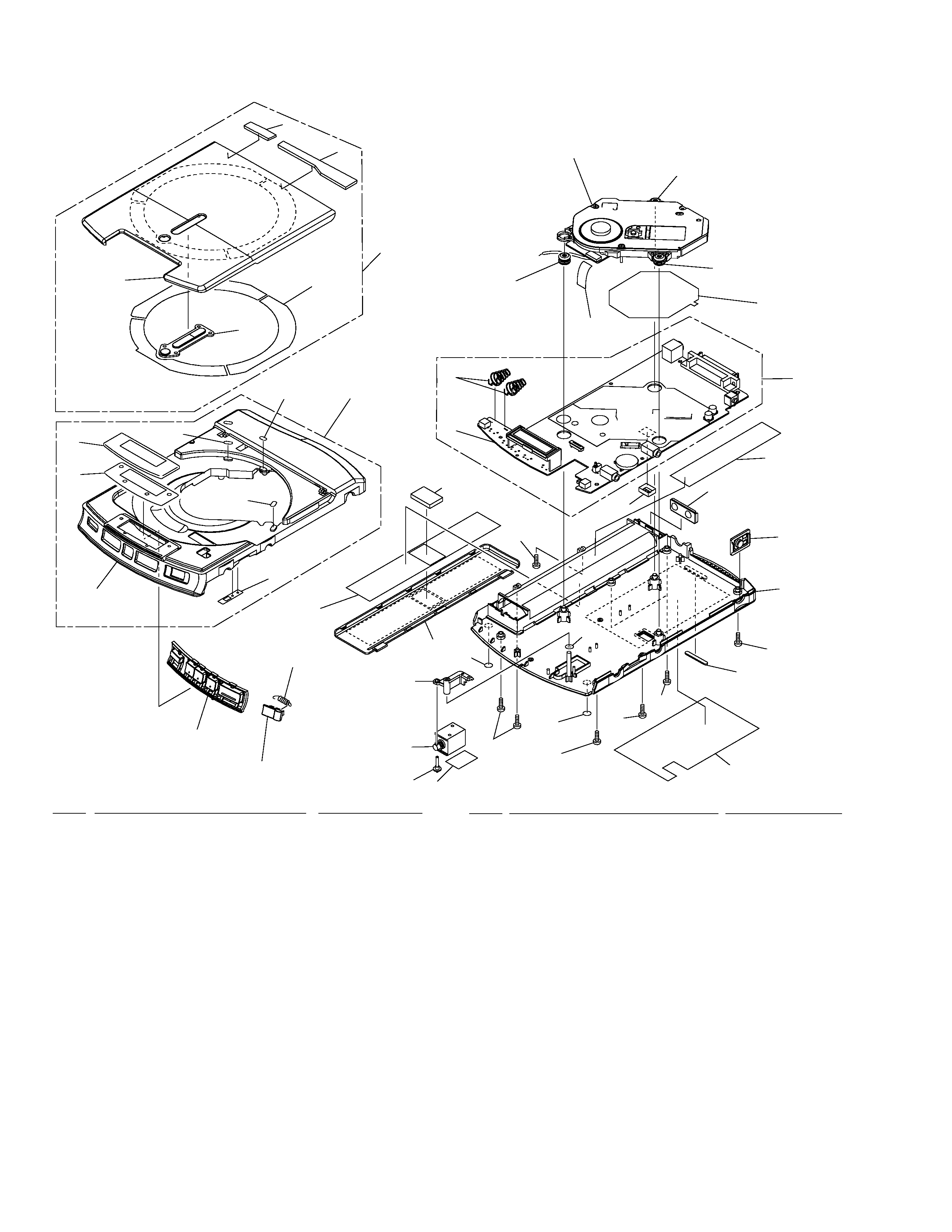
1
MOTHER BOARD ASSY
QWM1036
2
FLEXIBLE CORD
QDD1003
3
SERVO MECHANISM ASSY
QXX1014
4
PLUNGER
QXP1001
5
BATTERY TERMINAL A
QBH1005
6
OPEN SPRING
QBH1004
7
BATTERY TERMINAL B
QBK1004
8
FLOAT RUBBER
QEB1020
9
..................
10
LOCK LEVER
QNK1077
11
PLUNGER KNOB
QNK1071
12
LEG RUBBER
QEB1035
13
CHASSIS
QNK1066
14
BATTERY COVER
QNK1061
15
BUTTON ASSY
QNK1057
16
OPEN KNOB
QNK1058
17
POWER BUTTON
QNK1041
18
BODY ASSY
QXA1021
19
COVER SPRING
QBK1003
NSP
20
BODY
QNK1067
NSP
21
LCD WINDOW
QNK1046
22
TOP COVER ASSY
QXA1025
NSP
23
TOP COVER
QNK1065
NSP
24
TC WINDOW
QNK1047
25
MOTHER BOARD ASSY
QXX1015
26
DISC PAD
QED1008
27
SCREW
PPZ20P060FZK
28
CUSHION
QEB1022
29
TOP COVER SHEET
QED1009
NSP
30
LCD SHEET
QEC1018
31
LEG RUBBER F
QE1034
NSP
32
DOUBLE FACE TAPE
QEN1003
NSP
33
SHIELD SHEET
QEC1021
NSP
34
DIP SHIELD
QNH1026
35
WASHER
WA31D054D025
36
65 LABEL
DRW1659
NSP
37
TYPE NAME LABEL
QRW1078
38
TOP COVER PAD A
QEB1032
39
TOP COVER PAD B
QEB1033
2.2 EXTERIOR
22
29
24
23
21
26
26
26
30
20
19
37(1/2)
37(2/2)
18
15
16
6
28
14
31
35
10
4
11
27
27
31
27
27
12
27
13
17
7
25
5
33
8
8
8
2
Refer to " 2.3 SERVO MECHANISM
ASSY SECTION ".
1
27
34
36
32
39
38
3
Mark No.
Description
Parts No.
Mark No.
Description
Parts No.
PCP-PR24
5
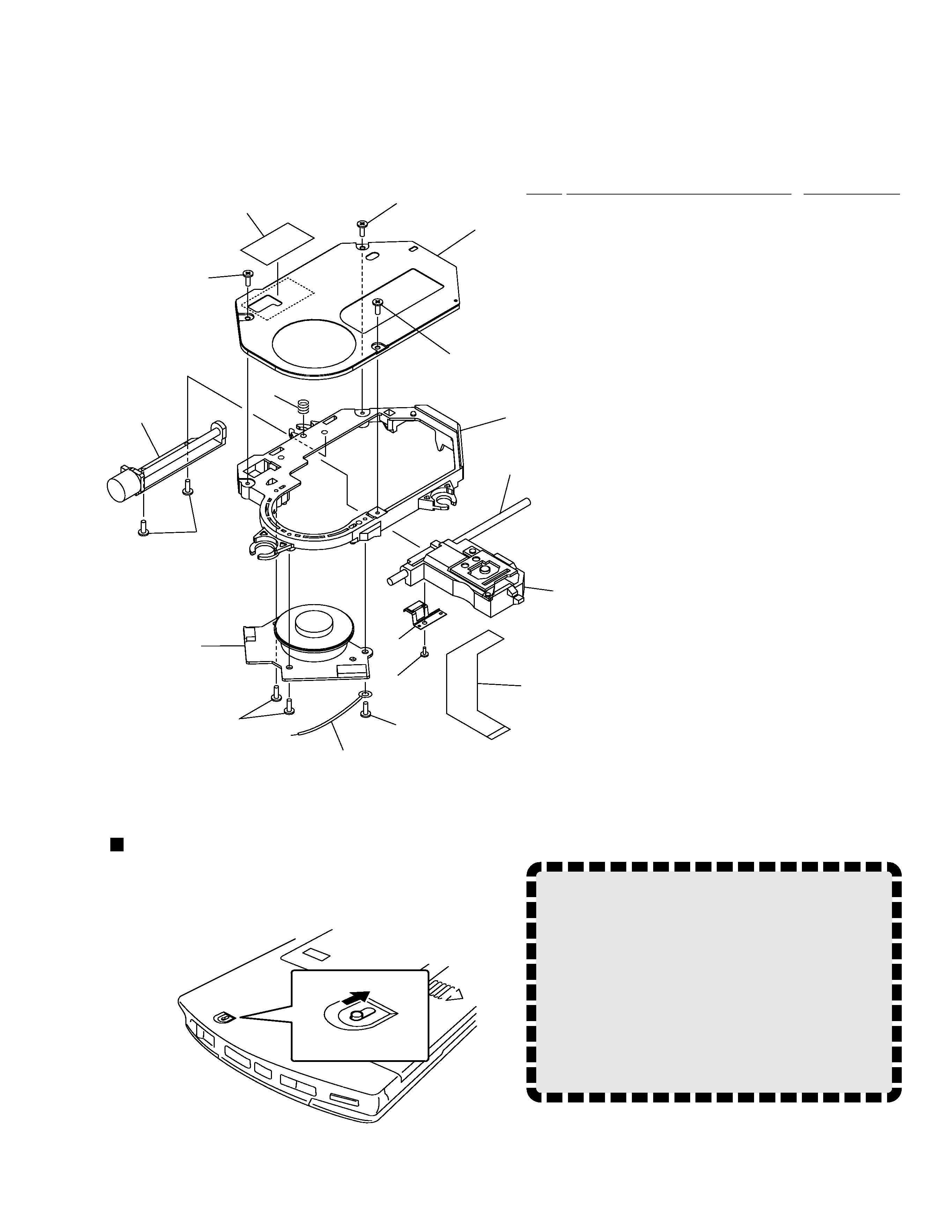
2.3 SERVO MECHANISM ASSY
Mark No.
Description
Parts No.
NSP
1
PICKUP ASSY
QWY1002
2
SCREW ( 1.7 X 4 )
ABA7022
3
SCREW ( B 1.7X 5 )
DBA1098
4
EARTH RUG ASSY
DDX1161
5
GUIDE SHAFT
DLA1785
6
TOP PLATE
DNH2222
7
MECHA FRAME
QNK1076
8
SCREW GUIDE S
DNK3345
9
SPINDLE MOTOR
QXM1004
10
STEPPING MOTOR
DXM1088
NSP
11
TOP PLATE SHEET
QEC1025
12
PU FLEXIBLE CORD
QNP1012
13
EARTH SPRING
DBH1359
NOTE!
Without drive power from the AC adapter or
from batteries, the top cover of this unit can
not be opened.
Do not force the top cover open while the disc
is spinning.
To realize a high transfer rate, the disc in this unit
spins at high speed.
If the top cover is opened while the disc is spinning,
the disc may be thrown out. So, do not open the
top cover while the disc is spinning.
10
13
3
9
3
4
3
8
2
12
1
5
7
3
6
3
3
11
To open the top cover without drive power
from the AC adapter or batteries:
Slide the emergency opening switch on the bottom of the
unit to open the top cover.