ORDER NO.
PIONEER CORPORATION 4-1, Meguro 1-chome, Meguro-ku, Tokyo 153-8654, Japan
PIONEER ELECTRONICS SERVICE, INC. P.O. Box 1760, Long Beach, CA 90801-1760, U.S.A.
PIONEER EUROPE NV Haven 1087, Keetberglaan 1, 9120 Melsele, Belgium
PIONEER ELECTRONICS ASIACENTRE PTE. LTD. 253 Alexandra Road, #04-01, Singapore 159936
PIONEER CORPORATION 2000
Model No.
Order No.
Remarks
M-F10/MYXJ
RRV2321
STEREO POWER AMPLIFIER
RRV2397
TZZA OCT. 2000 Printed in Japan
M-NS1
¶ This product is a system(s) component.
This product does not function properly independently ; to avoid malfunctions, be
sure to connect it to the prescribed system component(s), otherwise damage may
result.
¶ Please connect it to the STEREO CD/VCD TUNER XC-NS3V for adjustment and
operation inspection.
Component
Model
Service manual
Remarks
STEREO CD/VCD TUNER
XC-NS3V
RRV2395 (RRV2381)
STEREO POWER AMPLIFIER
M-NS1
RRV2397 (RRV2321)
This manual.
SPEAKER SYSTEM
S-NS1-LRW
RRV2371
DBD/DF
AC110127V/220230V/240V
With the voltage selector
THIS MANUAL IS APPLICABLE TO THE FOLLOWING MODEL(S) AND TYPE(S).
The voltage can be converted by the following method.
Power Requirement
Type
Model
M-NS1
MINIDISC RECORDER
MJ-NS1
RRV2399 (RRV2363)
¶ This service manual should be used together with the following manual(s).
M-NS1
2
PCB ASSEMBLIES
NSP
AMP MAIN Assy
AWM7499
AWM7525
P62
PRIMARY Assy
AWU7557
AWU7611
PACKING
P41
Paper Pattern
AAX7807
Not used
P42
System Cable (20P)
ADE7057
Not used
P43
AC Power Cord
ADG1154
Not used
P45
FM Wire Antenna
ADH7005
Not used
P46
Operating Instructions
ARC7301
Not used
(Dutch/Swedish/Spanish/Portuguese)
P47
Operating Instructions
ARE7264
Not used
(English/French/German/Italian)
P49
NSP
Warranty Card
ARY7022
Not used
P410
AM Loop Antenna
ATB7009
Not used
P411
Ferrite Core
ATX7007
Not used
P412
Remote Control Unit
AXD7271
Not used
P414
Stand A
AXG7096
Not used
P415
Stand B
AXG7097
Not used
P416
NSP
Lithium Battery (CR2025)
VEM1009
Not used
P417
Vinyl Bag (115
× 270 × 0.05)
Z21013
Not used
P418
NSP
Polyethylene Bag (0.03
× 230 × 340)
Z21038
Not used
P421
Spacer A
AHB7037
Not used
P422
Packing Case
AHD7941
AHD7951
EXTERIOR
P67
Power Transformer (T1)
ATS7278
ATS7282
P68
Fuse (FU1)
REK1025
REK1028
(T2AL250V)
(T4AL250V)
Fuse (T2AL250V, FU2, FU3)
Not used
REK1025
No. 1
P610
Rear Panel
ANC7935
ANC7936
P628
NSP
Label
ARW7101
Not used
Name Label
Not used
AAL7273
P629
Caution Label
ARW7112
ARW7114
P636
NSP
Fuse Card
Not used
AAX7099
No. 2
1. CONTRAST OF MISCELLANEOUS PARTS
M-NS1/DBD/DF and M-F10/MYXJ are constructed the same except for the following:
CONTRAST TABLE
NOTES :
Parts marked by " NSP " are generally unavailable because they are not in our Master Spare Parts List.
The
mark found on some component parts indicates the importance of the safety factor of the part.
Therefore, when replacing, be sure to use parts of identical designation.
Screws adjacent to
mark on the product are used for disassembly.
Reference Nos. indicate the pages and Nos. in the service manual for the base model.
When ordering resistors, first convert resistance values into code form as shown in the following examples.
Ex. 1
When there are 2 effective digits (any digit apart from 0), such as 560 ohm and 47k ohm (tolerance is shown by
J = 5%, and K = 10%).
560
= 56 × 101= 561 ................................................... RD1/4PU 5 6 1 J
47k
= 47 × 10 3 = 473 .................................................. RD1/4PU 4 7 3 J
0.5
= R50 ...................................................................... RN2H Â 5 0 K
1
= 1R0 ......................................................................... RS1P 1 Â 0 K
Ex. 2
When there are 3 effective digits (such as in high precision metal film resistors).
5.62k
= 562 × 10 1 = 5621 ........................................... RN1/4PC 5 6 2 1 F
Ref.
No.
Remarks
M-F10/MYXJ
M-NS1/DBD/DF
Part No.
Mark
Symbol and Description
Notes: The numbers in the remarks column correspond to the numbers on the " EXPLODED VIEWS ".
M-NS1
3
PRIMARY Assy
1: Refer to " SCHEMATIC DIAGRAM ".
AWU7611 and AWU7557 are constructed the same except for the following:
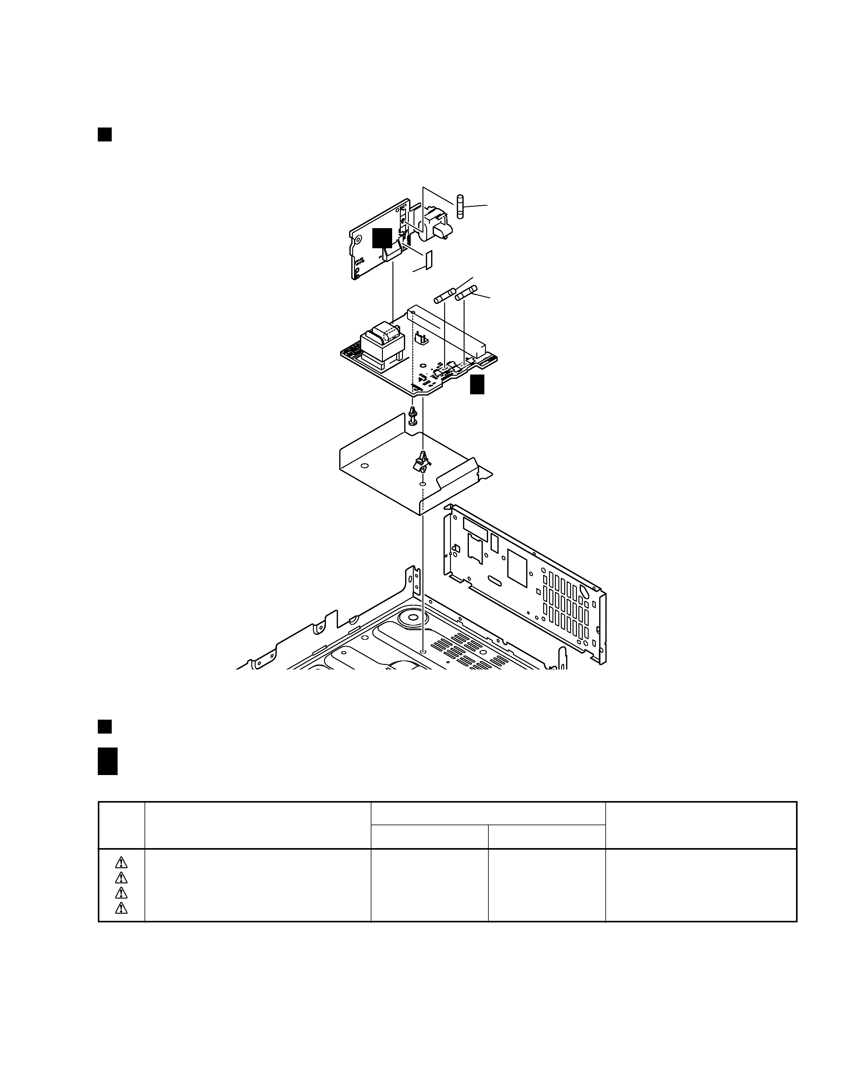
EXPLODED VIEWS
CONTRAST OF PCB ASSEMBLIES
2
Fuse (FU1)
AC IN Assy
PRIMARY Assy
1 (FU3)
1 (FU2)
Rear Panel
A
B F
B F
S1
Not used
XKX3001
1
T2
ATT7050
ATT7048
CN1
Not used
B4P7VH
1
H103H106
Not used
AKR7001
1
Mark
Symbol and Description
Part No.
AWU7557
AWU7611
Remarks
M-NS1
4
A
B
C
D
1
23
4
12
3
4
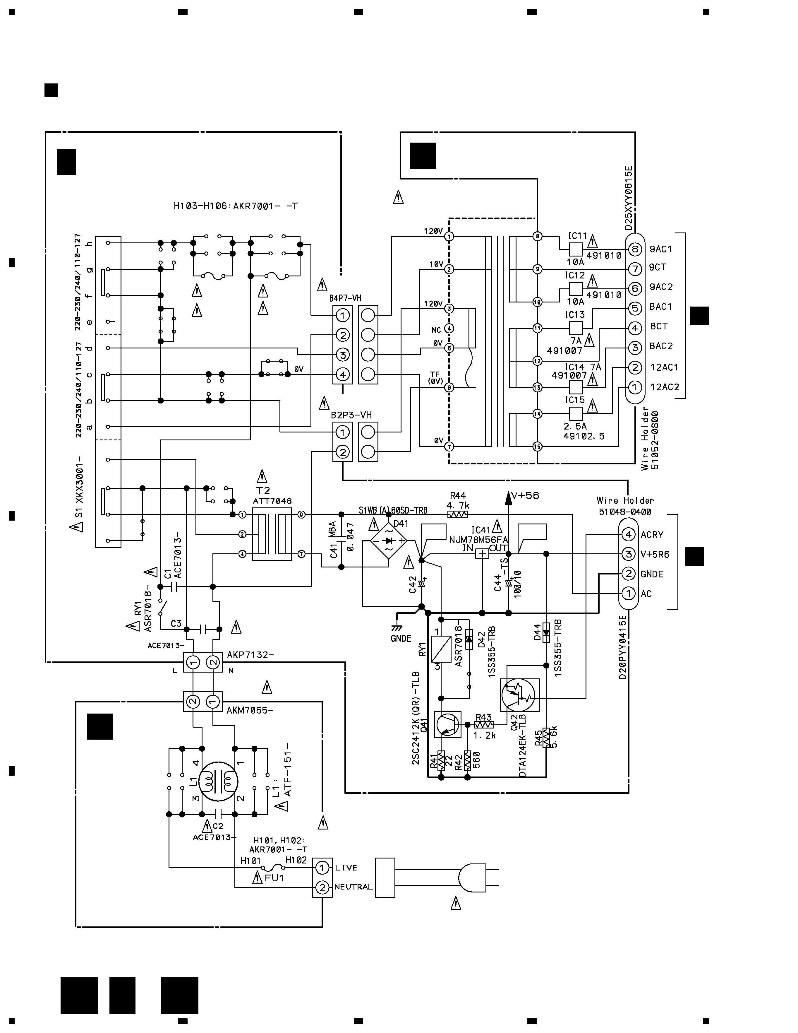
SCHEMATIC DIAGRAM
B F
PRIMARY ASSY
(AWU7611)
CN4
CN1
T1 POWER TRANSFORMER
ATS7282
C SECONDRY ASSY
(AWU7558)
CN11
H
J15
(T4A) REK1028
AC POWER CORD
ADG1158
BKP1046
AC110127V/220230V/240V
50/60Hz
AC IN ASSY
(AWU7556)
A
CN41
H
+12V
+5.6V
CN3
CN2
AN1
J41
2200/16
B F
H105
H106
FU3
T2A
REK1025
FU2
T2A
REK1025
H103
H104
C
A
ORDER NO.
PIONEER CORPORATION 4-1, Meguro 1-chome, Meguro-ku, Tokyo 153-8654, Japan
PIONEER ELECTRONICS SERVICE, INC. P.O. Box 1760, Long Beach, CA 90801-1760, U.S.A.
PIONEER EUROPE NV Haven 1087, Keetberglaan 1, 9120 Melsele, Belgium
PIONEER ELECTRONICS ASIACENTRE PTE. LTD. 253 Alexandra Road, #04-01, Singapore 159936
PIONEER CORPORATION 2000
STEREO POWER AMPLIFIER
RRV2321
TZZA JUNE 2000 Printed in Japan
M-F10
1. SAFETY INFORMATION .................................... 2
2. EXPLODED VIEWS AND PARTS LIST ............. 3
3. BLOCK DIAGRAM AND SCHEMATIC DIAGRAM
......................................................... 8
4. PCB CONNECTION DIAGRAM ....................... 14
5. PCB PARTS LIST ............................................. 20
6. ADJUSTMENT .................................................. 23
CONTENTS
7. GENERAL INFORMATION .............................. 24
7.1 DIAGNOSIS ................................................ 24
7.1.1 DISASSEMBLY ................................. 24
7.1.2 SINGLE OPERATION METHOD ...... 25
7.2 IC ................................................................ 27
8. PANEL FACILITIES AND SPECIFICATIONS
.................................................................... 28
MYXJ
AC220230V
NVXJ
AC230V
KUXJ/CA
AC120V
THIS MANUAL IS APPLICABLE TO THE FOLLOWING MODEL(S) AND TYPE(S).
Remarks
Power Requirement
Type
Model
M-F10
¶ This product is a system(s) component.
This product does not function properly independently ; to avoid malfunctions, be
sure to connect it to the prescribed system component(s), otherwise damage may
result.
¶ Please connect it to the STEREO CD TUNER XC-F10, for adjustment and operation
inspection.
Component
Model
Service manual
Remarks
STEREO CD TUNER
XC-F10
RRV2319 (ZVYXJ type)
RRV2341 (ZUXJ/CA type)
STEREO POWER AMPLIFIER
M-F10
RRV2321
This manual.
SPEAKER SYSTEM
S-F10-LRW
RRV2330 (XMD/EW type)
RRV2346 (XMD/UC type)
STEREO CASSETTE DECK
CT-F10
RRV2308