ORDER NO.
PIONEER ELECTRONIC CORPORATION 4-1, Meguro 1-Chome, Meguro-ku, Tokyo 153-8654, Japan
PIONEER ELECTRONICS SERVICE, INC. P.O. Box 1760, Long Beach, CA 90801-1760, U.S.A.
PIONEER ELECTRONIC (EUROPE) N.V. Haven 1087, Keetberglaan 1, 9120 Melsele, Belgium
PIONEER ELECTRONICS ASIACENTRE PTE. LTD. 501 Orchard Road, #10-00 Wheelock Place, Singapore 238880
PIONEER ELECTRONIC CORPORATION 1998
RRV2009
T ZZY OCT. 1998 Printed in Japan
DVD-ROM AUTO CHANGER
MAC-V700
CONTENTS
1. SAFETY INFORMATION .................................... 2
2. EXPLODED VIEWS AND PARTS LIST ............. 4
3. SCHEMATIC DIAGRAM ................................... 20
4. PCB CONNECTION DIAGRAM ....................... 56
5. PCB PARTS LIST ............................................. 67
6. ADJUSTMENT .................................................. 72
7. GENERAL INFORMATION .............................. 83
7.1 IC ................................................................ 83
7.2 DIAGNOSIS ................................................ 89
7.2.1 DISASSEMBLY ................................. 89
7.2.2 SERVICE MODE .............................. 95
7.3 BLOCK DIAGRAM .................................... 117
8. PANEL FACILITIES AND SPECIFICATIONS 119
THIS MANUAL IS APPLICABLE TO THE FOLLOWING MODEL(S) AND TYPE(S).
Type
Model
MAC-V700
Power Requirement
Remarks
TLW/TA/HK
O
AC110 - 240V
MAC-V700
2
1. SAFETY INFORMATION
This service manual is intended for qualified service technicians; it is not meant for the casual
do-it-yourselfer. Qualified technicians have the necessary test equipment and tools, and have been
trained to properly and safely repair complex products such as those covered by this manual.
Improperly performed repairs can adversely affect the safety and reliability of the product and may
void the warranty. If you are not qualified to perform the repair of this product properly and safely, you
should not risk trying to do so and refer the repair to a qualified service technician.
WARNING
This product contains lead in solder and certain electrical parts contain chemicals which are known to the state of California to cause
cancer, birth defects or other reproductive harm.
Health & Safety Code Section 25249.6 Proposition 65
1. SAFETY PRECAUTIONS
The following check should be performed for the
continued protection of the customer and service
technician.
ANY MEASUREMENTS NOT WITHIN THE LIMITS
OUTLINED ABOVE ARE INDICATIVE OF A PO-
TENTIAL SHOCK HAZARD AND MUST BE COR-
RECTED BEFORE RETURNING THE APPLIANCE
TO THE CUSTOMER.
2. PRODUCT SAFETY NOTICE
Many electrical and mechanical parts in the appli-
ance have special safety related characteristics. These
are often not evident from visual inspection nor the
protection afforded by them necessarily can be ob-
tained by using replacement components rated for
voltage, wattage , etc.
Replacement parts which have
these special safety
characteristics are identified in
this Service Manual.
Electrical components having such features are
identified by marking with a
on the schematics and
on the parts list in this Service Manual.
The use of a substitute replacement component which
does not have the same safety characteristics as the
PIONEER recommended replacement one, shown in
the parts list in this Service Manual, may create shock,
fire, or other hazards.
Product Safety is continuously under review and
new instructions are issued from time to time. For
the latest information, always consult the current
PIONEER Service Manual. A subscription to, or
ad-
ditional copies of, PIONEER Service Manual may be
obtained at a nominal charge from PIONEER.
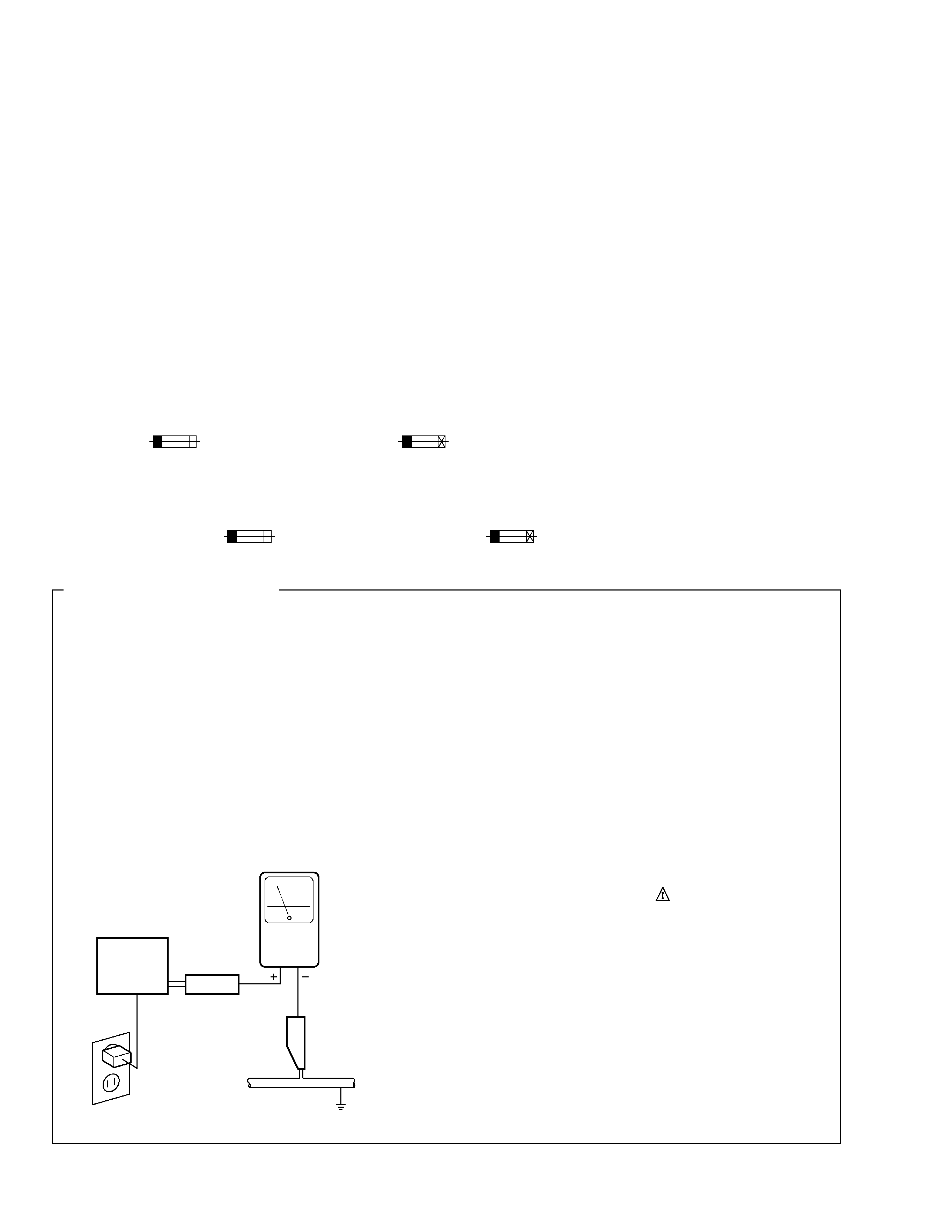
LEAKAGE CURRENT CHECK
Measure leakage current to a known earth ground
(water pipe, conduit, etc.) by connecting a leakage
current tester such as Simpson Model 229-2 or
equivalent between the earth ground and all exposed
metal parts of the appliance (input/output terminals,
screwheads, metal overlays, control shaft, etc.). Plug
the AC line cord of the appliance directly into a 120V
AC 60 Hz outlet and turn the AC power switch on. Any
current measured must not exceed 3.5 mA.
(FOR USA MODEL ONLY)
Also test with plug
reversed
(Using AC adapter
plug as required)
Device
under
test
Test all exposed
metal surfaces
Earth ground
Leakage
current
tester
Reading should
not be above
3.5 mA
AC Leakage Test
REMARQUE
(POUR MODÈLE CANADIEN SEULEMENT)
Les symboles de fusible
(fusible de type rapide) et/ou
(fusible de type lent) sur CCI indiquent que les
pièces de remplacement doivent avoir la même désignation.
NOTICE
(FOR CANADIAN MODEL ONLY)
Fuse symbols
(fast operating fuse) and/or
(slow operating fuse) on PCB indicate that replacement parts
must be of identical designation.
MAC-V700
3
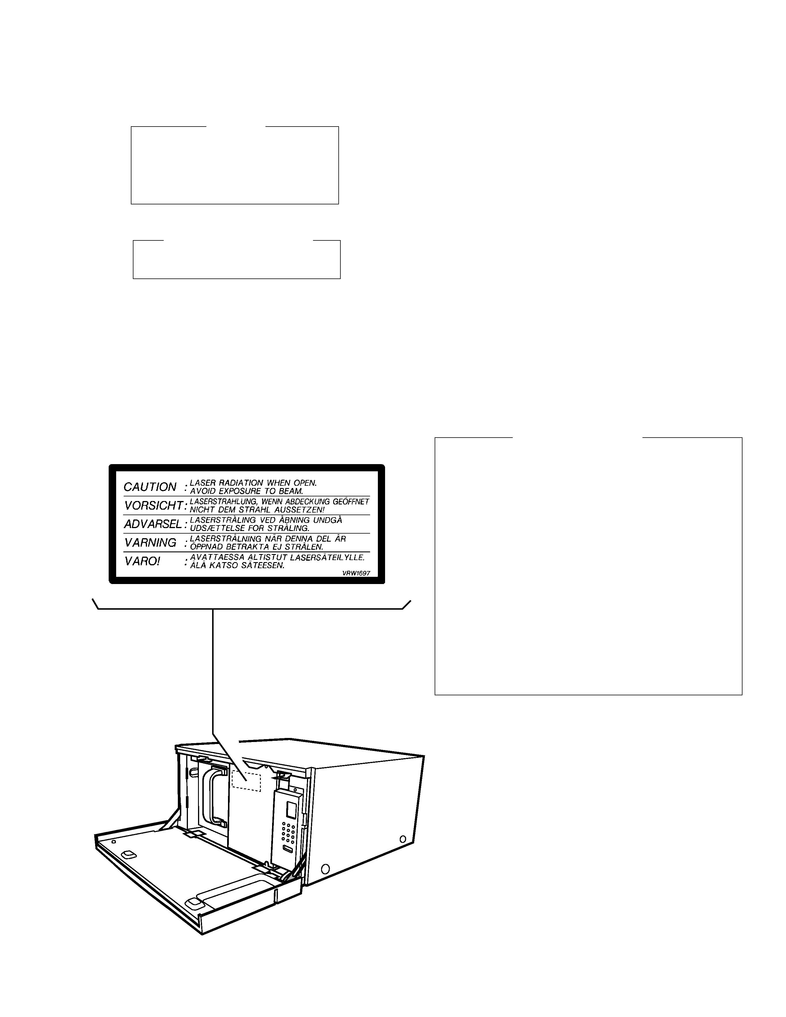
1. Laser Interlock Mechanism
The position of the switch (S601) for detecting loading
completion is detected by the system microprocessor, and
the design prevents laser diode oscillation when the
switch(S601) is not on CLAMP terminal side (CLAMP
signal is OFF high level.)
Thus, the interlock will no longer function if the
switch(S601) is deliberately set to CLAMP terminal side.
(low level).
In the test mode* the interlock mechanism will not
function.
Laser diode oscillation will continue, if pin 13 of
LA9700(IC102) on the DVPL board assy connected to
high level, or else the terminais of Q111 or Q112 are
shorted to each other .
2. When the cover is opened, close viewing of the objective
lens with the naked eye will cause exposure to a Class 1
laser beam.
IMPORTANT
THIS PIONEER APPARATUS CONTAINS
LASER OF CLASS 1.
SERVICING OPERATION OF THE APPARATUS
SHOULD BE DONE BY A SPECIALLY
INSTRUCTED PERSON.
LASER DIODE CHARACTERISTICS
MAXIMUM OUTPUT POWER: 7 mw
WAVELENGTH: 640 nm(DVD) , 780 nm(CD-ROM)
Additional Laser Caution
* Refer to page 79.
LABEL CHECK
MAC-V700
4
11
6
4
5
12
2
1
15
3
7
9
8
13
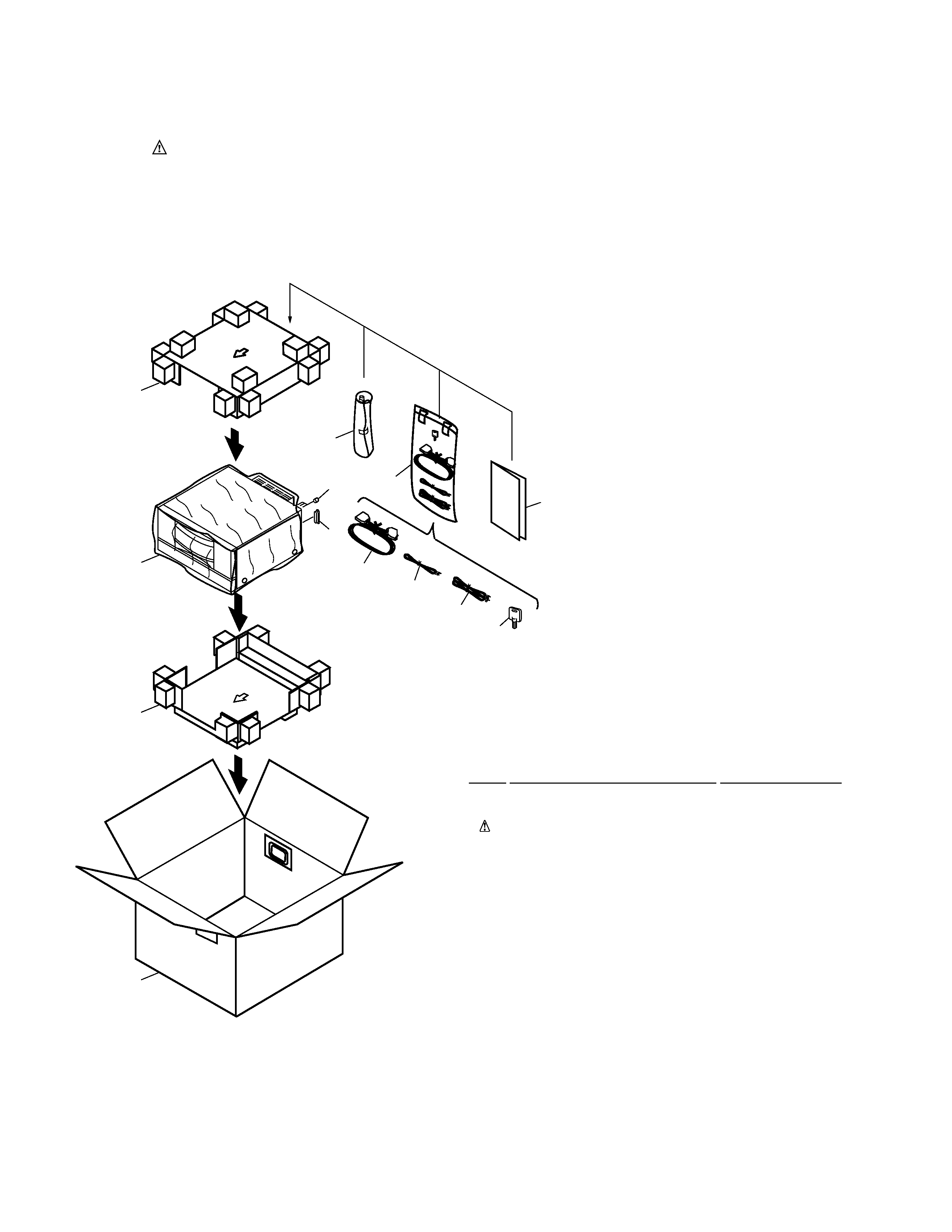
Mark No.
Description
Part No.
1
Audio Cord (L= 2 m)
DDE1112
2
Video Cord (L= 2 m)
ADE1059
3
Power Cord
DDG1079
4
Pin Jack Cap
DEC2130
5
Dust Cap
DEC2234
6
Door Key
DNK1698
7
Top Pad
DHA1406
8
Bottom Pad
DHA1407
9
Mirror Mat
VHL1014
10
· · · · ·
11
Operating Instructions
DRB1230
(English/ Chinese)
12
Control Cable (L= 2 m)
DDC1008
13
Packing Case
DHG1838
14
· · · · ·
15
Polyethylene Bag
Z21-038
PARTS LIST
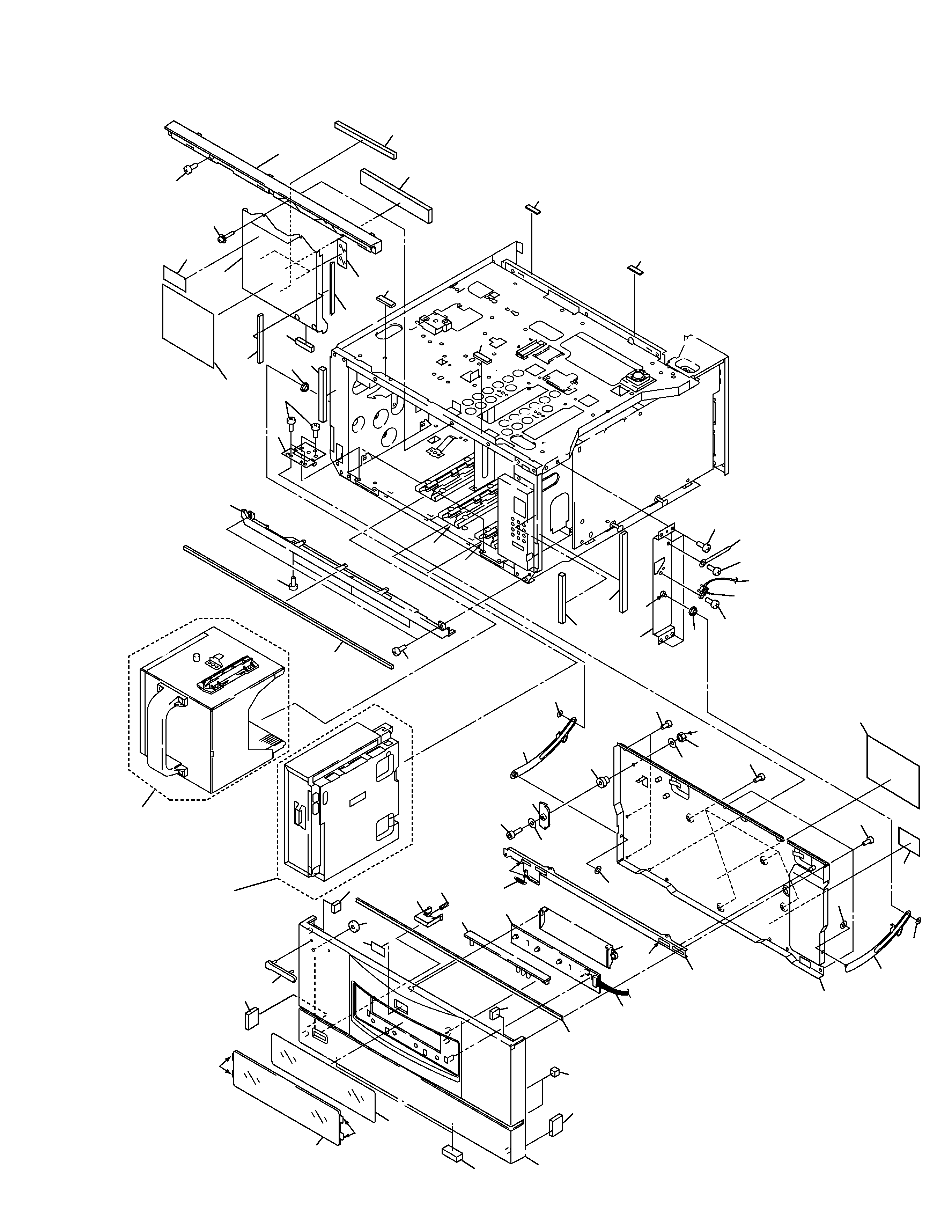
2. EXPLODED VIEWS AND PARTS LIST
2.1 PACKING
NOTES :
÷ Parts marked by " NSP " are generally unavailable because they are not in our Master Spare Parts List.
÷ The
mark found on some component parts indicates the importance of the safety factor of the part.
Therefore, when replacing, be sure to use parts of identical designation.
÷ Screw adjacent to
mark on the product are used for disassembly.
MAC-V700
5
23
15
7
11
13
6
25
46
8
45
31
40
34
32
39
49
28
47
26
33
19
22
1
2
17
16
30
18
33
4
3
5
14
11
27
45
29
51
44(2/2)
29
41
29
28
48
35
9
64
21
38
20
35
36
24
49 61
28
37
44(1/2)
50
42
43
13
*2
*1
*1
*1
*3
*3
Player -2
Player -1
Refer to
2.7 DVD PLAYER
SECTION
Refer to
2.6 DISC STOCKER
SECTION
53
54
59
62
52
60
55
63
56
61
58
56
58
*
*
*
1: Floil
2: Screw Lock
3: Adhesive
2.2 MAIN SECTION (1)