
BRIDGEABLE FOUR-CHANNEL POWER AMPLIFIER
Owner's Manual
GM-6300T
Visit www.pioneer.co.uk (or www.pioneer.eu)
to register your product
EN
G
L
IS
H
Q
sound.vision.soul
MAN-GM-6300T-GB.fm Page 1 Thursday, November 16, 2006 4:23 PM
2
EN
G
L
IS
H
Contents
Before Using This Product .................. 2
Visit our website .......................................... 2
In case of trouble ........................................ 2
CAUTION .................................................... 3
CAUTION .................................................... 3
WARNING ................................................... 3
Setting the Unit ..................................... 4
Gain Control ................................................ 4
BFC (Beat Frequency Control) Switch ........ 4
Power Indicator ........................................... 4
LPF (Low-Pass Filter)/HPF (High-
Pass Filter) Select Switch ......................... 4
Input Select Switch ..................................... 4
Connecting the Unit ............................. 5
Connection Diagram ................................... 5
Connecting the Power Terminal ................. 6
Connecting the Speaker Output
Terminals ................................................. 6
Using the Speaker Input ............................. 7
Connecting the Speakers and
Input Wires ............................................... 7
Installation ............................................ 8
Example of installation on the floor
mat or on the chassis ............................... 9
Specifications ....................................... 9
Additional information ....................... 10
Before Using This Product
Thank you for purchasing this PIONEER product. Before attempting operation, be sure
to read this manual.
Private households in the 25 member states of the EU, in Switzerland and Norway
may return their used electronic products free of charge to designated collection
facilities or to a retailer (if you purchase a similar new one).
For countries not mentioned above, please contact your local authorities for the correct
method of disposal.
By doing so you will ensure that your disposed product undergoes the necessary
treatment, recovery and recycling and thus prevent potential negative effects on the
environment and human health.
Visit our website
Visit us at the following site:
· Register your product. We will keep the details of your purchase on file to help you
refer to this information in the event of an insurance claim such as loss or theft.
· We offer the latest information about Pioneer Corporation on our website.
In case of trouble
When the unit does not operate properly, contact your dealer or the nearest authorized
PIONEER Service Station.
If you want to dispose this product, do not mix it with general household
waste. There is a separate collection system for used electronic products
in accordance with legislation that requires proper treatment, recovery
and recycling.
MAN-GM-6300T-GB.fm Page 2 Thursday, November 16, 2006 4:23 PM
3
EN
G
L
IS
H
Before Using This Product
! CAUTION
Never replace the fuse with one of greater value or rating than the original fuse. Use
of an improper fuse could result in overheating and smoke and could cause damage
to the product and injury including burns.
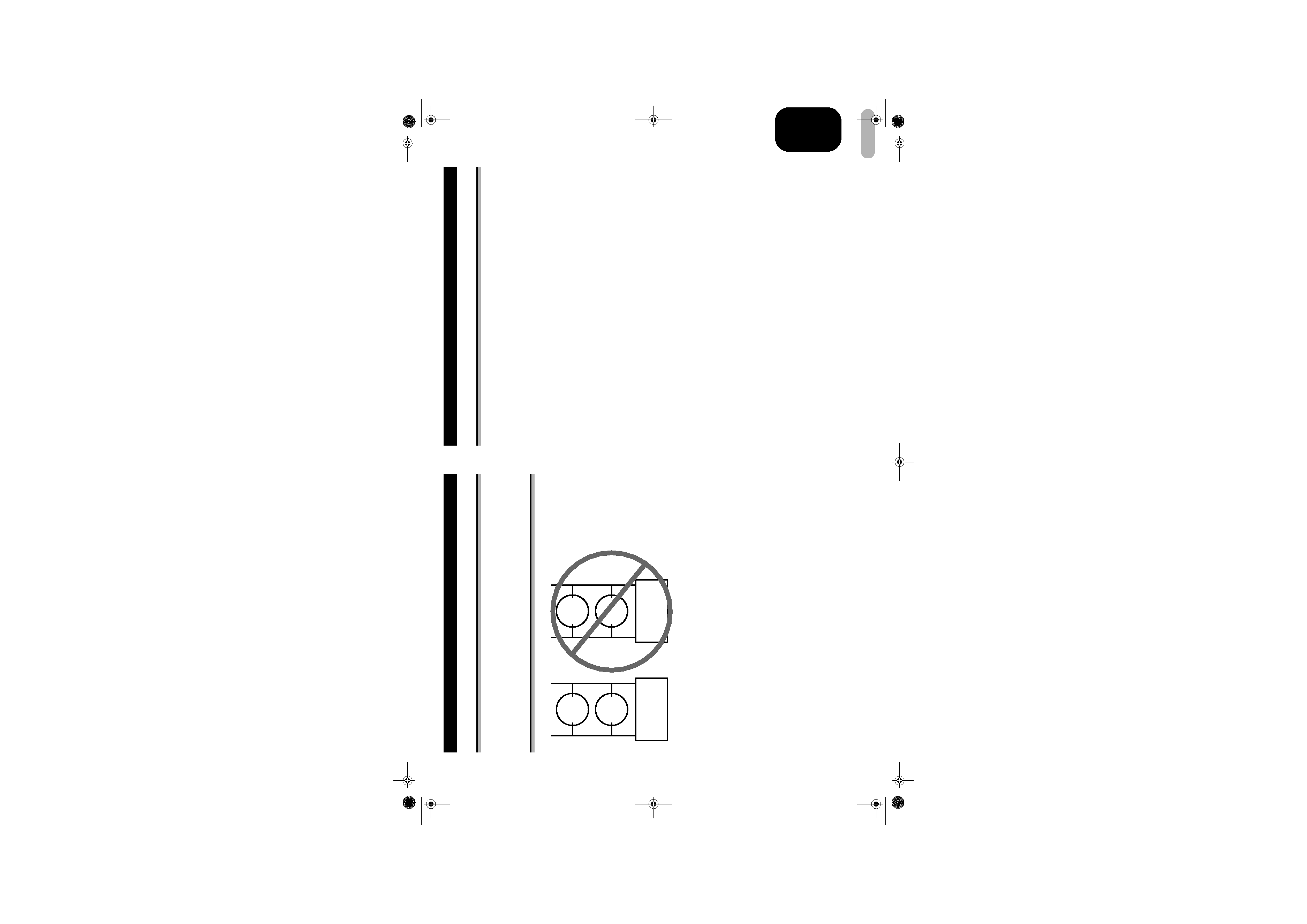
! CAUTION
Do NOT install or use your Pioneer amplifier by wiring speakers rated at 4
$ (or lower)
in parallel to achieve a 2
$ (or lower) bridged mode (Diagram B).
Amplifier damage, smoke, and overheating could result from improper bridging. The
amplifier surface could also become hot to the touch and minor burns could result.
To properly install or use a bridged mode for a two-channel amplifier and achieve a
4
$ load, wire two 8 $ speakers in parallel with Left + and Right (Diagram A) or use
a single 4
$ speaker. For a four-channel amplifier, follow the speaker output
connection diagram for bridging as shown on the back of your amplifier, and wire two
8
$ speakers in parallel to achieve a 4 $ load or use a single 4 $ speaker per channel.
If you have any questions or concerns, please contact your local authorized Pioneer
dealer or call Pioneer customer service.
+-
+-
+-
+-
Diagram A - Proper
Diagram B - Improper
8
$
Speaker
8
$
Speaker
Pioneer Amplifier
Pioneer Amplifier
4
$ Bridged Mode
2
$ Bridged Mode
L+
R-
L+
R-
4
$
Speaker
4
$
Speaker
WARNING
· Always use the special red battery and ground wire [RD-223], which is sold
separately. Connect the battery wire directly to the car battery positive terminal (+)
and the ground wire to the car body.
· Do not touch the amplifier with wet hands. Otherwise you may get an electric shock.
Also, do not touch the amplifier when it is wet.
· For traffic safety and to maintain safe driving conditions, keep the volume low
enough so that you can still hear normal traffic sound.
· Check the connections of the power supply and speakers if the fuse of the
separately sold battery wire or the amplifier fuse blows. Detect the cause and solve
the problem, then replace the fuse with another one of the same size and rating.
· To prevent malfunction of the amplifier and speakers, the protective circuit will cut
the power supply to the amplifier (sound will stop) when an abnormal condition
occurs. In such a case, switch the power to the system OFF and check the
connection of the power supply and speakers. Detect the cause and solve the
problem.
· Contact the dealer if you cannot detect the cause.
· To prevent an electric shock or short-circuit during connection and installation, be
sure to disconnect the negative () terminal of the battery beforehand.
· Confirm that no parts are behind the panel when drilling a hole for installation of the
amplifier. Be sure to protect all cables and important equipment such as fuel lines,
brake lines and the electrical wiring from damage.
· DO NOT allow amplifier to come into contact with liquids due to, for example, the
location where the amplifier is installed. Electrical shock could result. Also, amplifier
and speaker damage, smoke, and overheating could result from contact with liquids.
In addition, the amplifier surface and the surface of any attached speakers could
become hot to the touch and minor burns could result.
MAN-GM-6300T-GB.fm Page 3 Thursday, November 16, 2006 4:23 PM
4
EN
G
L
IS
H
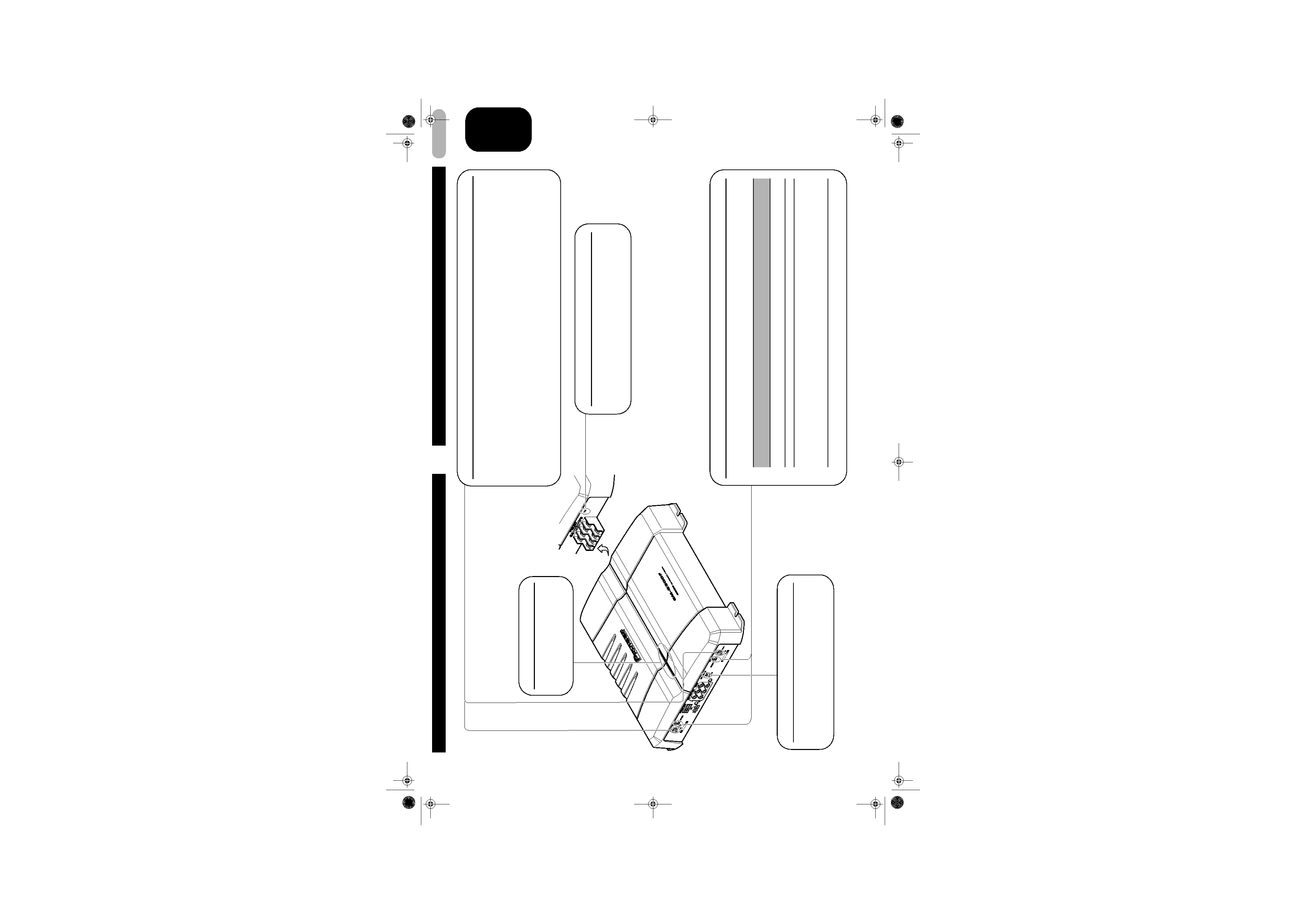
Setting the Unit
Gain Control
Adjusting the gain controls A and B will help match the output of the car stereo to the Pioneer
amplifier. Normally, set the gain controls to the NORMAL position. If the output is low, even
when the volume of the car stereo is turned up, turn these controls clockwise. If there is
distortion when the volume of the car stereo is turned up, turn these controls counter-
clockwise.
· If you only use one input plug, set the gain controls for speaker outputs A and B to the same position.
· When using with an RCA equipped car stereo (standard output of 500 mV), set to the NORMAL
position. When using with an RCA equipped Pioneer car stereo with max. output of 4 V or more,
adjust level to match the car stereo output level.
BFC (Beat Frequency Control) Switch
If you hear a beat while listening to an MW/LW
broadcast with your car stereo, change the BFC
switch using a small standard tip screwdriver.
Power Indicator
The power indicator lights
when the power is switched
on.
LPF (Low-Pass Filter)/HPF (High-Pass Filter) Select Switch
Set the LPF/HPF select switch as follows according to the type of speaker that is connected
to the speaker output connector and the car stereo system:
LPF/HPF Select
Switch
Audio frequency range
to be output
Speaker Type
Remarks
LPF (Left)
80 Hz and below with 12 dB/
oct. cut off slope
Subwoofer
Connect a subwoofer.
OFF (Center)
Full range
Full range
HPF (Right)
80 Hz and above with 12 dB/
oct. cut off slope
Full range
Use if you want to cut the
very low frequency range
because it is not
necessary for the
speakers you are using.
Input Select Switch
For two-channel input, slide this switch to the
left. For four-channel input, slide this switch to
the right.
MAN-GM-6300T-GB.fm Page 4 Thursday, November 16, 2006 4:23 PM
5
EN
G
L
IS
H
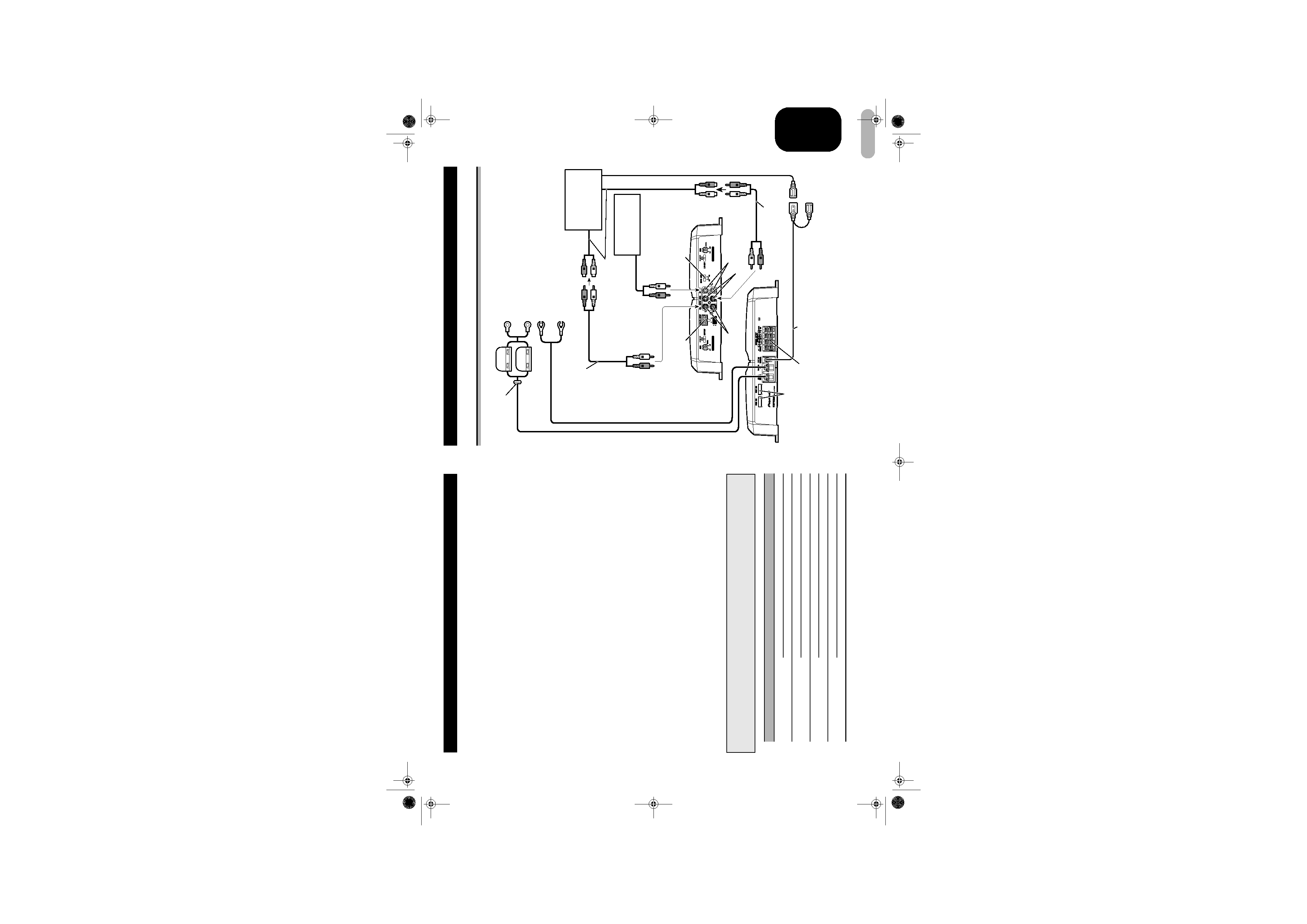
Connection Diagram
Grommet
Special red battery wire [RD-223] (sold separately)
After making all other connections at the amplifier,
connect the battery wire terminal of the amplifier to the
positive (+) terminal of the battery.
Ground wire (black) [RD-223] (sold separately)
Connect to metal body or chassis.
Speaker output terminal
See the "Connecting the
Speakers and Input Wires"
section for speaker
connection instructions.
System remote control wire (sold separately)
Connect the male terminal of this wire to
the system remote control terminal of the car
stereo (SYSTEM REMOTE CONTROL). The female terminal can be
connected to the auto-antenna relay control terminal. If the car
stereo does not have a system remote control terminal, connect the
male terminal to the power terminal through the ignition switch.
RCA input jack A
Fuse (30 A)
Speaker input terminal
See the "Using the Speaker Input"
section.
Connecting wires with
RCA pin plugs (sold
separately).
Car stereo with
RCA output jacks
Fuse (25 A)
x 2
Fuse (30 A)
Front side
Back side
Amplifier with RCA
input jacks
External Output
If only one input plug is used,
do not connect anything to
RCA input jack B.
Input Select Switch
For two-channel input, slide this
switch to the left. For four-
channel input, slide this switch
to the right.
RCA input jack B
RCA output jack
Connecting wires with RCA pin
plugs (sold separately).
RCA input
Connecting the Unit
! CAUTION
· Disconnect the negative () terminal of the battery to avoid the risk of short-circuit and
damage to the unit.
· Secure the wiring with cable clamps or adhesive tape. To protect the wiring, wrap adhesive
tape around it where they lie against metal parts.
· Do not route wires where they will get hot, for example where the heater will blow over them.
If the insulation heats up, it may become damaged, resulting in a short-circuit through the
vehicle body.
· Make sure that wires will not interfere with moving parts of the vehicle, such as the gearshift,
handbrake or seat sliding mechanism.
· Do not shorten any wires. Otherwise the protection circuit may fail to work when it should.
· Never feed power to other equipment by cutting the insulation of the power supply wire to
tap from the wire. The current capacity of the wire will be exceeded, causing overheating.
· Never replace the fuse with one of greater value or rating than the original fuse. Use of an
improper fuse could result in overheating and smoke and could cause damage to the
product and injury including burns.
! CAUTION:
To prevent damage and/or injury
· Do not ground the speaker wire directly or connect a negative () lead wire for several
speakers.
· This unit is for vehicles with a 12-volt battery and negative grounding. Before installing it in
a recreational vehicle, truck or bus, check the battery voltage.
· If the car stereo is kept on for a long time while the engine is at rest or idling, the battery may
go dead. Turn the car stereo off when the engine is at rest or idling.
· If the system remote control wire of the amplifier is connected to the power terminal through
the ignition switch (12 V DC), the amplifier will always be on when the ignition is on
regardless of whether the car stereo is on or off. Because of this, the battery could go dead
if the engine is at rest or idling.
· Speakers to be connected to the amplifier should conform with the standards listed below.
If they do not conform, they may catch fire, emit smoke or become damaged. The speaker
impedance must be 2
$ to 8 $. But in case of two-channel and other bridge connections, the
speaker impedance must be 4
$ to 8 $.
· Install and route the separately sold battery wire as far away as possible from the speaker
wires. Install and route the separately sold battery wire, ground wire, speaker wires and the
amplifier as far away as possible from the antenna, antenna cable and tuner.
· Cords for this product and those for other products may be different colors even if they have
the same function. When connecting this product to another product, refer to the supplied
manuals of both products and connect cords that have the same function.
Speaker Channel
Speaker Type
Power
Four-channel
Subwoofer
Nominal input: Min. 70 W
Other than subwoofer
Max. input: Min. 120 W
Two-channel
Subwoofer
Nominal input: Min. 200 W
Other than subwoofer
Max. input: Min. 300 W
Three-channel
Subwoofer
Nominal input: Min. 70 W
Speaker output A
Other than subwoofer
Max. input: Min. 120 W
Three-channel
Subwoofer
Nominal input: Min. 200 W
Speaker output B
Other than subwoofer
Max. input: Min. 300 W
MAN-GM-6300T-GB.fm Page 5 Thursday, November 16, 2006 4:23 PM