ORDER NO.
CRT2926
PUB. NO.
CRT2926
AUDIO SYSTEM
HEAD UNIT
Manufactured for TOYOTA
by PIONEER CORPORATION
SC430
Service
Manual
VEHICLE
DESTINATION
PRODUCED AFTER
TOYOTA PART No.
ID No.
PIONEER MODEL No.
P6833
FX-MG8117ZT-02/UC
LEXUS SC430
U.S.A., CANADA
August 2002
86120-24391
P6832
FX-MG8217ZT-02/UC
2
1
234
12
34
F
E
D
C
B
A
FX-MG8117ZT-02/UC
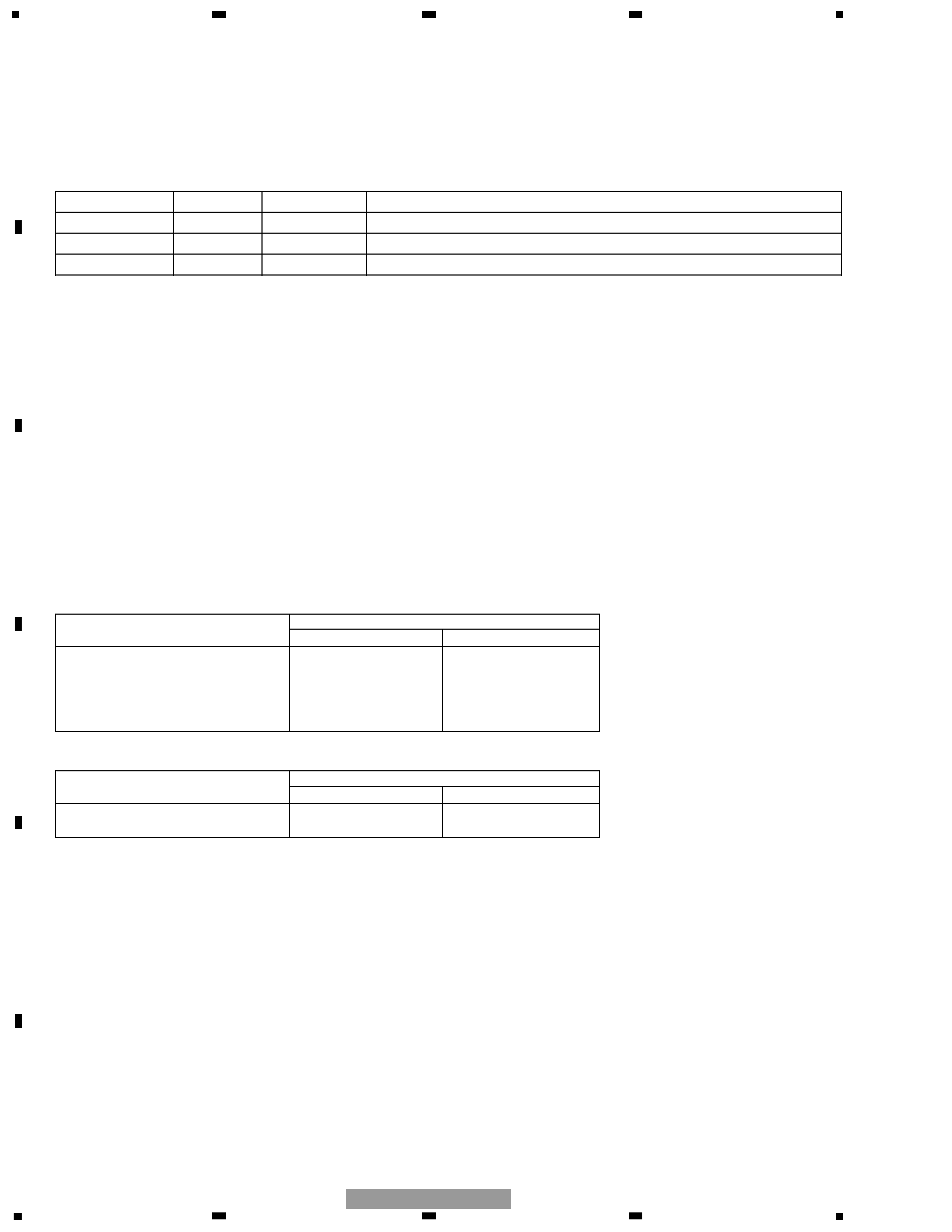
- This service manual should be used together with the manual(s) listed below.
For the parts numbers, adjustments, etc. which are not shown in this manual, refer to the following
manual(s).
- The differences from the FX-MG8217ZT/UC:
1. Change of the microcomputer (due to RBDS application)
The network-follow and TRAF cut-in functions have been deleted.
2. Change of the ANT+B circuit due to employment of the new-type antenna in the vehicles (Supply cur-
rent up: 100mA max.)
EXPLODED VIEWS AND PARTS LIST
EXTERIOR(Page 4)
- EXTERIOR SECTION PARTS LIST
* : Non spare part
Part No.
Mark No. Description
FX-MG8217ZT/UC
FX-MG8117ZT-02/UC
10 Main Unit
CWM7046
CWM8638
45 Door
CAT2166
CAT2422
64 Knob Unit
CXB6372
CXB5185
65 Grille Unit
CXB8316
CXB8313
Sheet(Service)
CXX1505
Not used
- EXTERIOR SECTION PARTS LIST
Part No.
Mark No. Description
FX-MG8217ZT/UC
FX-MG8217ZT-02/UC
10 Main Unit
CWM7046
CWM8638
45 Door
CAT2166
CAT2421
Model No.
Order No.
Mech. Module Remarks
FX-MG8217ZT/UC
CRT2584
CX-631
CRT1640
2L
Cassette Mech. Module:Mech.Description, Disassembly
CX-890
CRT2376
G1
CD Mech. Module:Circuit Description, Mech.Description, Disassembly
3
5
6
7
8
F
E
D
C
B
A
5
6
7
8
FX-MG8117ZT-02/UC
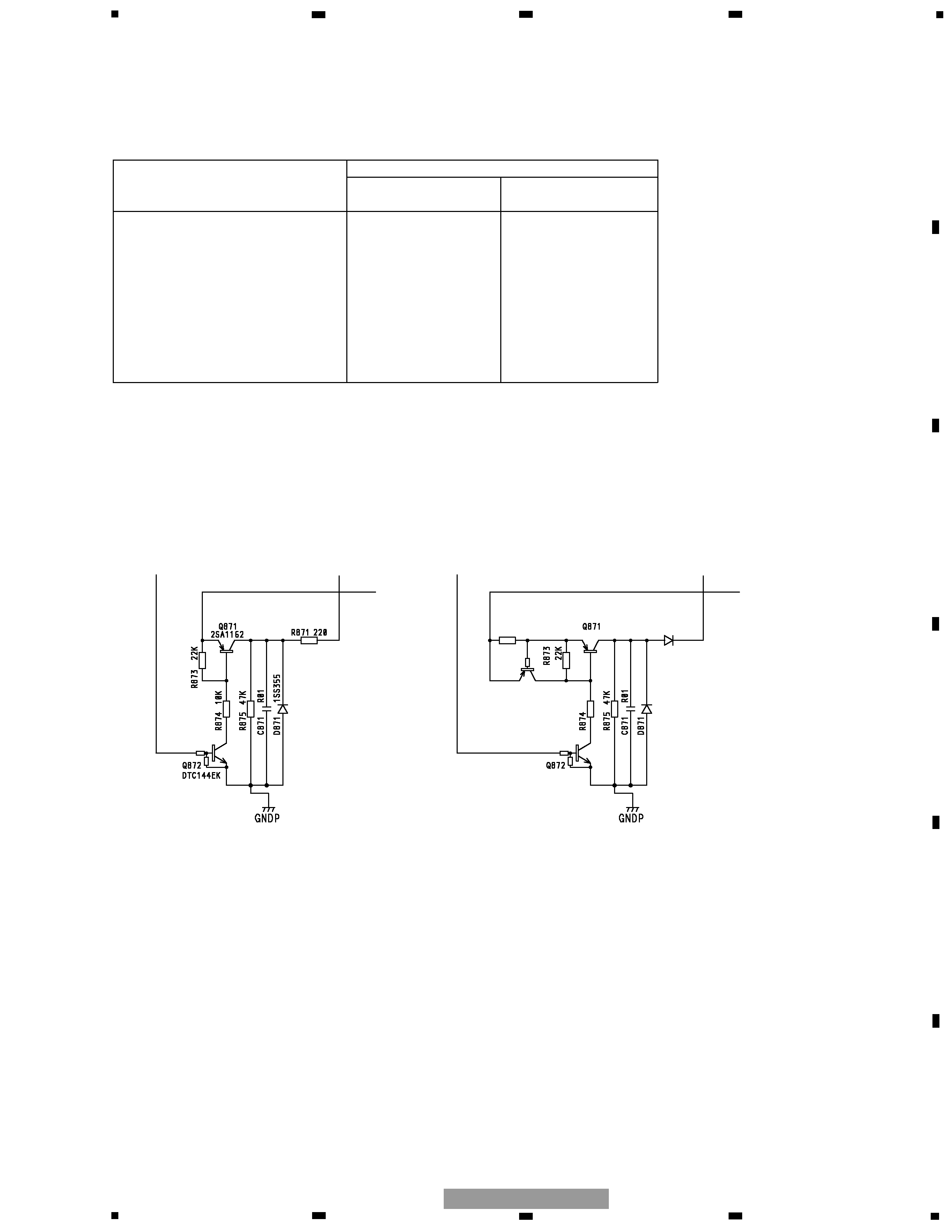
ELECTRICAL PARTS LIST(Page 60)
MAIN UNIT
Part No.
FX-MG8217ZT/UC
FX-MG8117ZT-02/UC
Symbol and Description
FX-MG8217ZT-02/UC
IC 601 IC
PD5569C
PD5824A
Q 871 Transistor
2SA1162
2SB1260
Q 872 Transistor
DTC144EK
DTC124EU
Q 873 Transistor
Not used
DTA143TK
D 871 Diode
1SS355
1SR154-400
D 872 Diode
Not used
ERA15-02VH
R 871
RD1/4PU221J
Not used
R 872
Not used
RS1/10S4R7J
R 874
RS1/10S103J
RS1/10S472J
ANTENNA POWER SWITCH
(FX-MG8217ZT/UC)
ANTENNA POWER SWITCH
(FX-MG8117ZT-02/UC, FX-MG8217ZT-02/UC)
D872
ERA15-02VH
2SB1260
1SR154-400
4R7K
DTC124EU
Q873
DTA143TK
R872
4R7
4
Capacitor
Connector
P.C.Board
Chip Part
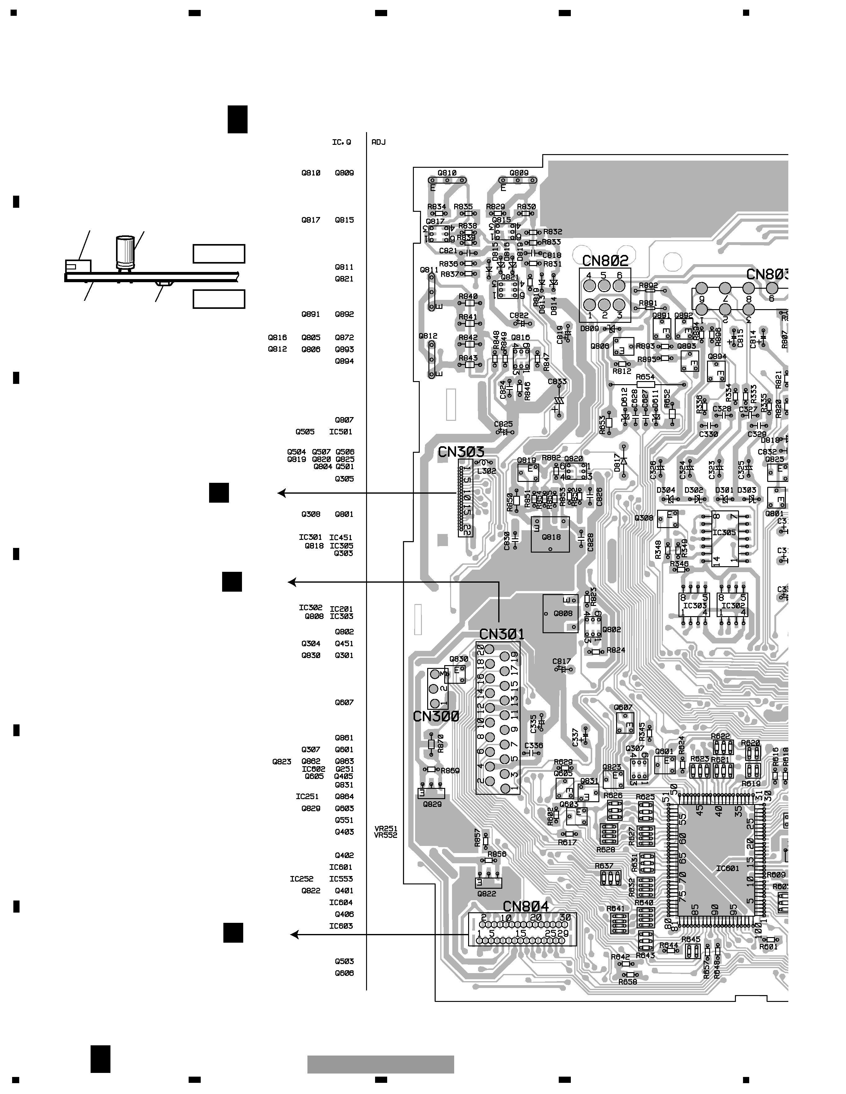
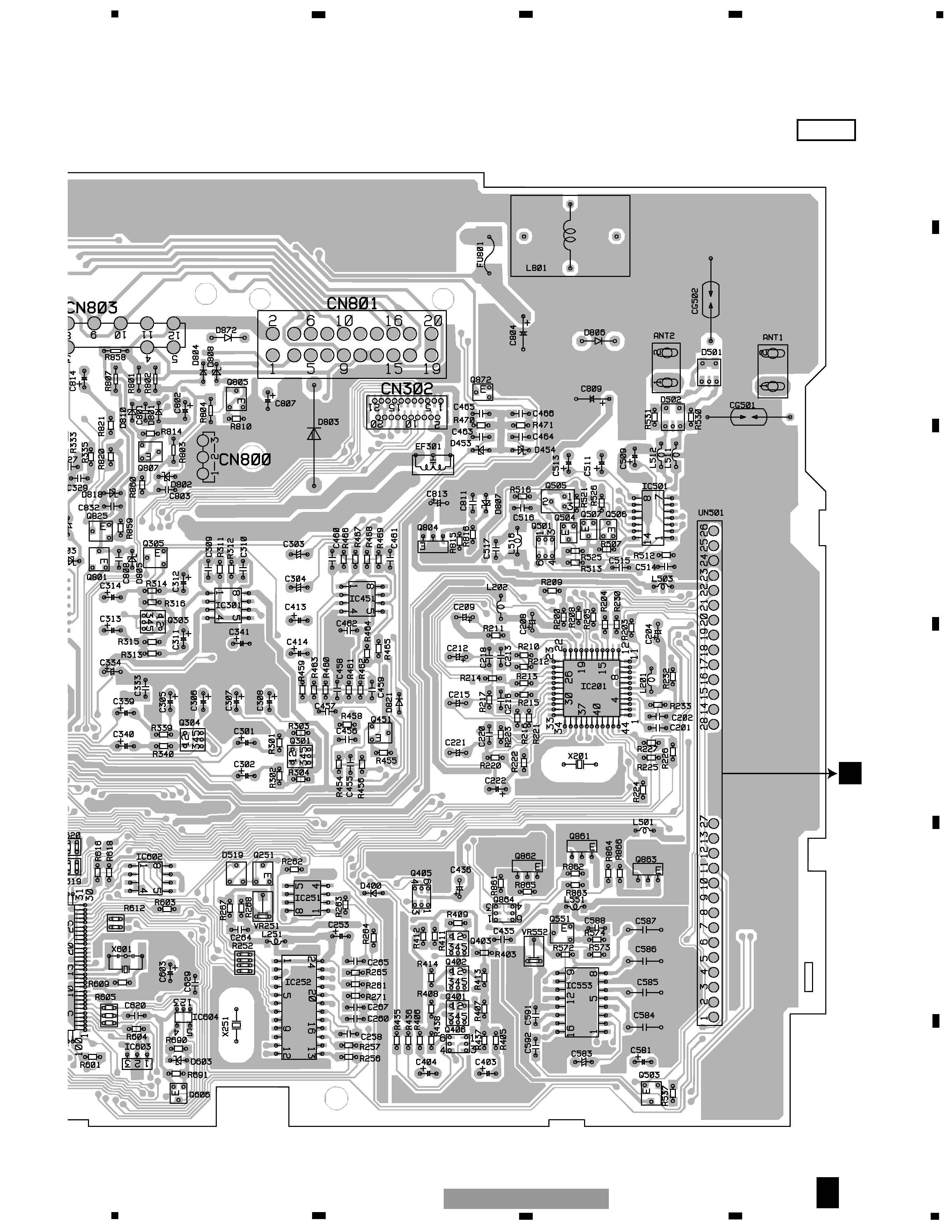
MAIN UNIT
SIDE B
SIDE A
NOTE FOR PCB DIAGRAMS
1.The parts mounted on this PCB
include all necessary parts for
several destination.
For further information for
respective destinations, be sure
to check with the schematic dia-
gram.
2.Viewpoint of PCB diagrams
Q CN702
N CN251
C CN902
1
234
12
34
F
E
D
C
B
A
FX-MG8117ZT-02/UC
PCB CONNECTION DIAGRAM
MAIN UNIT
A F
A F
5
SIDE A
FRONT
B
5
6
7
8
F
E
D
C
B
A
5
6
7
8
FX-MG8117ZT-02/UC
A F