
Operating Instructions
Manual de instruções
F-208
FM/AM DIGITAL-SYNTHESIZER TUNER
2
En
The exclamation point within an equilateral
triangle is intended to alert the user to the
presence of important operating and
maintenance (servicing) instructions in the
literature accompanying the appliance.
The lightning flash with arrowhead symbol,
within an equilateral triangle, is intended to
alert the user to the presence of uninsulated
"dangerous voltage" within the product's
enclosure that may be of sufficient
magnitude to constitute a risk of electric
shock to persons.
IMPORTANT
CAUTION:
TO PREVENT THE RISK OF ELECTRIC
SHOCK, DO NOT REMOVE COVER (OR
BACK). NO USER-SERVICEABLE PARTS
INSIDE. REFER SERVICING TO QUALIFIED
SERVICE PERSONNEL.
CAUTION
RISK OF ELECTRIC SHOCK
DO NOT OPEN
D3-4-2-1-1_En
WARNING:
BEFORE PLUGGING IN THE UNIT FOR THE FIRST
TIME, READ THE FOLLOWING SECTION CAREFULLY.
The voltage of the available power supply differs
according to country or region. Be sure that the
power supply voltage of the area where this unit
will be used meets the required voltage (e.g., 230V
or 120V) written on the rear panel.
D3-4-2-1-4_En
WARNING: No naked flame sources, such as
lighted candle, should be placed on the apparatus.
If naked flame sources accidentally fall down, fire
spread over the apparatus then may cause fire.
D3-4-2-1-7a_En
WARNING: Slot and openings in the cabinet are
provided for ventilation and to ensure reliable
operation of the product and to protect it from
overheating, to prevent fire hazard, the openings
should never be blocked and covered with items,
such as newspapers, table-cloths, curtains, etc. Also
do not put the apparatus on the thick carpet, bed,
sofa, or fabric having a thick pile.
D3-4-2-1-7b_En
Operating Environment
Operating environment temperature and humidity:
+5 ºC +35 ºC (+41 ºF +95 ºF); less than 85 %RH
(cooling vents not blocked)
Do not install in the following locations
· Location exposed to direct sunlight or strong artificial
light
· Location exposed to high humidity, or poorly
ventilated location
D3-4-2-1-7c_En
CAUTION
The POWER switch does not completely separates
the unit from the MAINS in off position. Therefore
install the unit suitable places easy to disconnect
the MAINS plug in case of the accident. The MAINS
plug of unit should be unplugged from the wall
socket when left unused for a long period of time.
D3-4-2-2-2b_En
Thank you for buying this Pioneer product.
Please read through these operating instructions so you
will know how to operate your unit properly. After you
have finished reading the instructions, keep them in a
safe place for future reference.
In some countries or regions, the shape of the power
plug and power outlet may sometimes differ from that
shown in the explanatory drawings. However, the method
of connecting and operating the unit is the same.
WARNING: The apparatus is not waterproofs, to
prevent fire or shocks hazard, do not expose this
apparatus to rain or moisture and do not put any
water source near this apparatus, such as vase,
flower pot, cosmetics container and medicine
bottle etc.
D3-4-2-1-3_En
D3-4-2-1-5_En
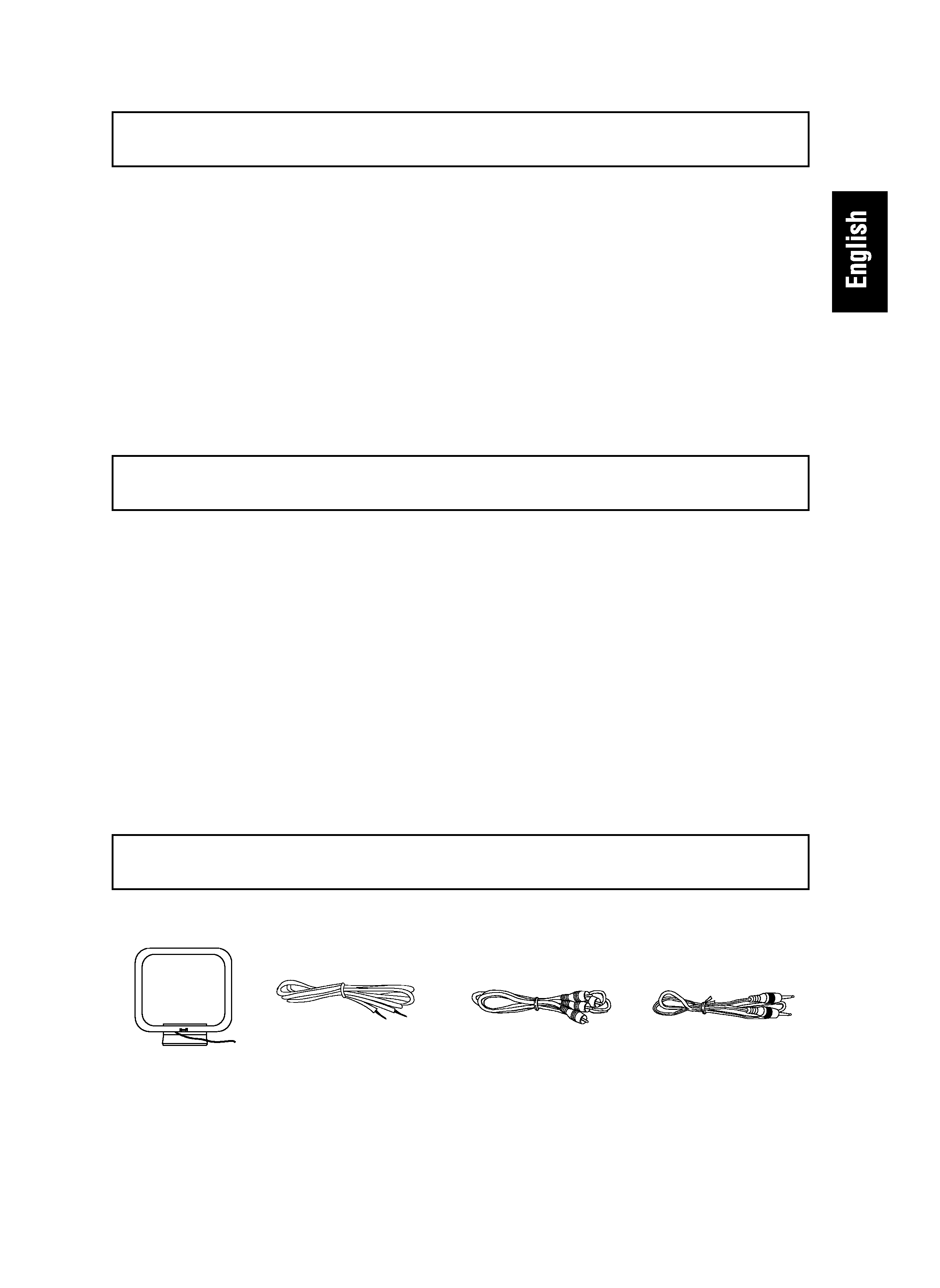
Voltage selector
You can find the voltage selector switch on the rear
panel of multi-voltage models.
The factory setting for the voltage selector is 220 V.
Please set it to the correct voltage for your country
or region.
· For Taiwan, please set to 110 V before using.
Before changing the voltage, disconnect the AC power
cord. Use a medium size screwdriver to change the
voltage selector switch.
Medium-size screwdriver
This product is for general household purposes. Any
failure due to use for other than household purposes
(such as long-term use for business purposes in a
restaurant or use in a car or ship) and which
requires repair will be charged for even during the
warranty period.
K041_En
3
En
CONTENTS
FEATURES ............................................. 3
CHECKING THE ACCESSORIES ........... 3
INSTALLATION ...................................... 4
CONNECTIONS ...................................... 5
ANTENNA CONNECTIONS ......................
6
FRONT PANEL FACILITIES ................... 7
BASIC TUNING OPERATIONS ............ 10
AUTO AND MANUAL TUNING ..............
10
DIRECT ACCESS TUNING .....................
11
PRESETTING STATIONS ..................... 12
PRESET STATIONS ................................
12
PRESET STATION TUNING ...................
13
MEMORY SCAN .....................................
13
MANUAL STATION NAME MEMORY .....
14
TROUBLESHOOTING .......................... 16
SPECIFICATIONS ................................. 17
7 RF ATT
A built-in attenuator (RF ATT) can be switched on or
off for proper reception of strong boradcast stations.
7 Random 30-station presetting
A total of 30 FM and AM stations can be preset into
the memory circuit.
7 Manual station name memory
Using up to 4 characters, you can store a name of
your choice for preset FM/AM broadcast stations 1
to 30.
FEATURES
7 Memory scan
This function receives preset stations within a class
(A, B or C) in order, letting you select a desired sta-
tion while checking what program the station is broad-
casting.
7 Energy-saving design
This unit is designed to use minimal electricity when
power is switched OFF (during Standby).
Regarding the value of the power consumption in
standby mode, refer to "SPECIFICATIONS" on page
17.
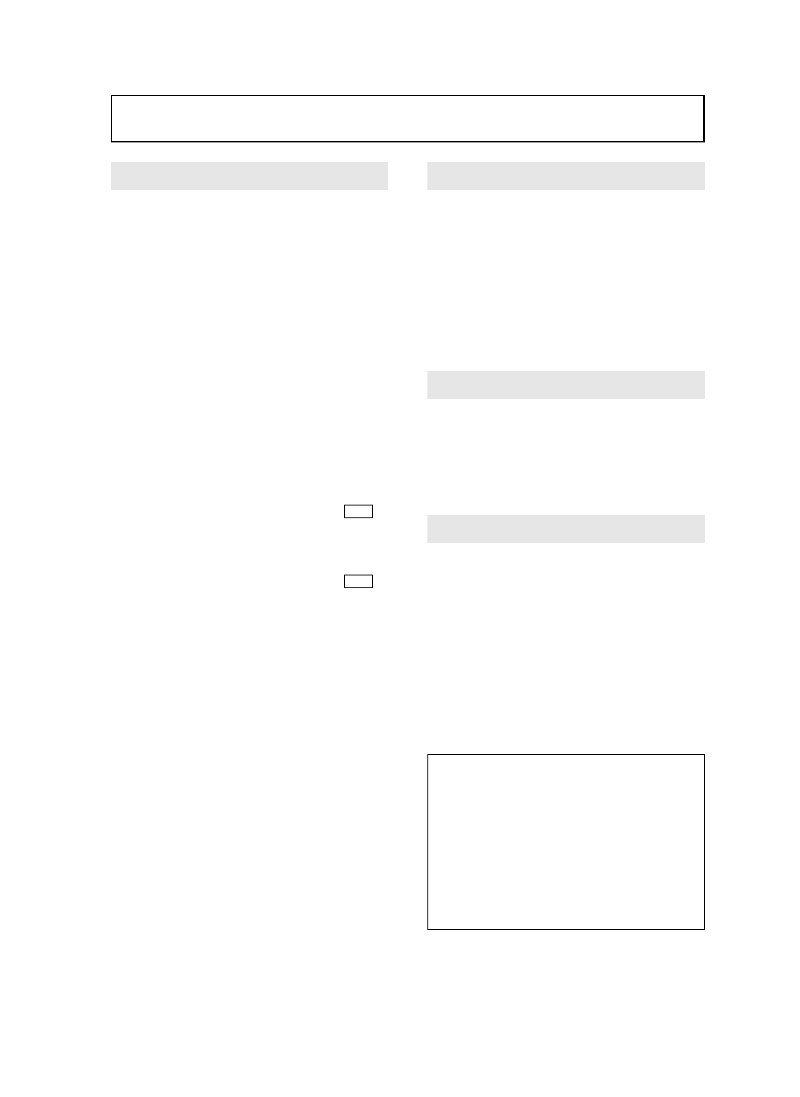
CHECKING THE ACCESSORIES
FM T-type antenna
AM loop antenna
Audio cord
Control cord
4
En
INSTALLATION
LOCATION
Install the tuner in a well-ventilated location
where it will not be exposed to high
temperatures or humidity.
Do not install the tuner in a location which is exposed to
direct rays of the sun, or near hot appliances or radiators.
Excessive heat can adversely affect the cabinet and in-
ternal components. Installation of the tuner in a damp or
dusty environment may result in a malfunction or acci-
dent. (Also avoid installation near cookers, etc., where
the tuner may be exposed to smoke, steam, or heat.)
POWER-CORD CAUTION
Handle the power cord by the plug. Do not pull out the
plug by tugging the cord and never touch the power cord
when your hands are wet as this could cause a short cir-
cuit or electric shock. Do not place the unit, a piece of
furniture, etc., on the power cord, or pinch the cord. Never
make a knot in the cord or tie it with other cords. The
power cords should be routed such that they are not likely
to be stepped on. A damaged power cord can cause fire
or give you an electrical shock. Check the power cord
once in a while. When you find it damaged, ask your near-
est PIONEER authorized service center or your dealer for
a replacement.
Maintenance of external surfaces
¶ Use a polishing cloth or dry cloth to wipe off dust
and dirt.
¶ When the surfaces are very dirty, wipe with a soft
cloth dipped in some neutral cleanser diluted five
or six times with water, and wrung out well, and
then wipe again with a dry cloth. Do not use furni-
ture wax or cleaners.
¶ Never use thinners, benzine, insecticide sprays or
other chemicals on or near this unit, since these
will corrode the surfaces.
CONDENSATION
When this unit is brought into a warm room from previ-
ously cold surroundings or when the room temperature
rises sharply,condensation may from inside,and the unit
may not be able to attain its full performance. In this case,
allow the unit to stand for about an hour or raise the room
temperature gradually.
CHANNEL STEP SETTING
Before using the unit for the first time, be sure to set the
correct channel step (FM and AM) for your area.
If the channel step setting is incorrect, tuning to the cor-
rect frequency will not be possible, and poor sound qual-
ity due to distortion and noise will prevent reproduction
of the received signal.
FM 100 kHz, AM 10 kHz:
Set to this position for areas with an FM reception step
of 100 kHz and AM 10 kHz.
FM 50 kHz, AM 9 kHz:
Set to this position, for areas with an FM reception step
of 50 kHz and AM 9 kHz.
NOTE:
When unsure about the channel allocation for your area,
consult your dealer for correct information.
To change channel steps
Setting the FM channel step to 100kHz and the AM
channel step to 10kHz:
When power is in standby, press the STANDBY/ON
switch while pressing STATION CALL button 0/10 to
switch power ON.
Setting the FM channel step to 50kHz and the AM
channel step to 9kHz:
When power is in standby, press the STANDBY/ON
switch while pressing STATION CALL button
9
to
switch power ON.
5
En
INPUT
PHONO
CD
TUNER
L
R
GND
IN
OUT
L
R
FM
UNBAL
75
AM
LOOP
ANTENNA
ANTENNA
CONTROL
OUTPUT
220V
240V
110V
120 - 127V
220 - 240V
110 - 127V
TWO VOLTAGE SERECTORS
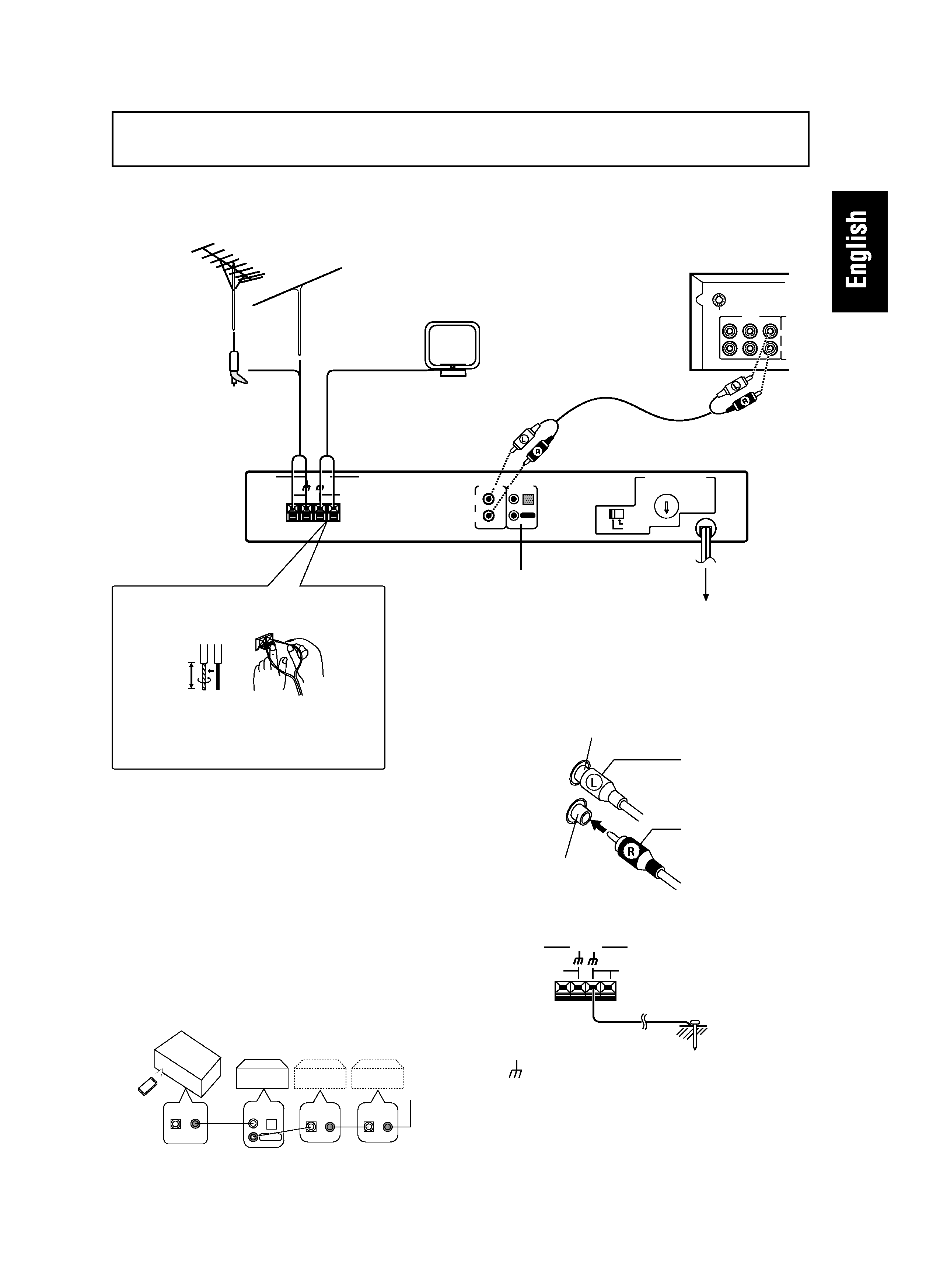
CONNECTIONS
CONTROL terminals
When using together with a Pioneer component bear-
ing the
Î mark, connect the CONTROL IN terminal on
the rear panel of the tuner to the CONTROL OUT termi-
nal on the component using the supplied control cord.
This will enable the tuner to be controlled from a dis-
tance with the remote control unit supplied with the
component.
When this feature is not used, connection is not neces-
sary.
¶ For instructions regarding connection and operation,
please refer to the operating instructions of your ste-
reo component.
Before making or changing the connections, switch off
the power switch and disconnect the power cord from
the AC outlet.
CONTROL
IN
OUT
CONTROL
IN
OUT
CONTROL
IN
OUT
CD Player
Cassette Deck
CONTROL
IN
OUT
Stereo
Amplifier
Outdoor FM
antenna
Stereo amplifier
Plug the power cord
into an ACwall socket.
Accessory AM loop antenna
Accessory FM T-type antenna
CONTROL terminals
Connecting the FM T-type antenna
and AM loop antenna
15 mm
1. Strip and twist the ends of the wires.
2. With tabs beneath connector down, insert
wires from antenna.
Accessory
Audio cord
Pin plug connecting cord
¶ Connect the white plug to the white terminal (L) and
the red plug to the red terminal (R).
¶ Make sure that the connections are secure.
Left channel
Right channel
White plug
Red plug
NOTE:
The
(signal earth) helps reduce noise when an antenna
is connected. It is not a safety earth.
Antenna ground
CAUTION:
Never make the ground connection to a gas pipe as sparks
can cause the gas ignite.
FM
UNBAL
75
AM
LOOP
ANTENNA
ANTENNA
F-208