2
<DRB1369>
D3-4-2-1-1_En-A
The exclamation point within an equilateral
triangle is intended to alert the user to the
presence of important operating and
maintenance (servicing) instructions in the
literature accompanying the appliance.
The lightning flash with arrowhead symbol,
within an equilateral triangle, is intended to
alert the user to the presence of uninsulated
"dangerous voltage" within the product's
enclosure that may be of sufficient
magnitude to constitute a risk of electric
shock to persons.
CAUTION:
TO PREVENT THE RISK OF ELECTRIC
SHOCK, DO NOT REMOVE COVER (OR
BACK). NO USER-SERVICEABLE PARTS
INSIDE. REFER SERVICING TO QUALIFIED
SERVICE PERSONNEL.
CAUTION
RISK OF ELECTRIC SHOCK
DO NOT OPEN
IMPORTANT
Operating Environment
Operating environment temperature and humidity:
+5 ºC +35 ºC (+41 ºF +95 ºF); less than 85 %RH
(cooling vents not blocked)
Do not install this unit in a poorly ventilated area, or in
locations exposed to high humidity or direct sunlight (or
strong artificial light)
D3-4-2-1-7c_A_En
If the AC plug of this unit does not match the AC
outlet you want to use, the plug must be removed
and appropriate one fitted. Replacement and
mounting of an AC plug on the power supply cord of
this unit should be performed only by qualified
service personnel. If connected to an AC outlet, the
cut-off plug can cause severe electrical shock. Make
sure it is properly disposed of after removal.
The equipment should be disconnected by removing
the mains plug from the wall socket when left
unused for a long period of time (for example, when
on vacation).
D3-4-2-2-1a_A_En
CAUTION
The POWER switch on this unit will not completely
shut off all power from the AC outlet. Since the
power cord serves as the main disconnect device for
the unit, you will need to unplug it from the AC outlet
to shut down all power. Therefore, make sure the
unit has been installed so that the power cord can
be easily unplugged from the AC outlet in case of an
accident. To avoid fire hazard, the power cord should
also be unplugged from the AC outlet when left
unused for a long period of time (for example, when
on vacation).
D3-4-2-2-2a_A_En
WARNING
This equipment is not waterproof. To prevent a fire
or shock hazard, do not place any container filed
with liquid near this equipment (such as a vase or
flower pot) or expose it to dripping, splashing, rain
or moisture.
D3-4-2-1-3_A_En
WARNING
The voltage of the available power supply differs
according to country or region. Be sure that the
power supply voltage of the area where this unit
will be used meets the required voltage (e.g., 230V
or 120V) written on the rear panel.
D3-4-2-1-4_A_En
Before plugging in for the first time, read the following
section carefully.
VENTILATION CAUTION
When installing this unit, make sure to leave space
around the unit for ventilation to improve heat
radiation (at least 5 cm at rear, and 5 cm at each
side).
WARNING
Slots and openings in the cabinet are provided for
ventilation to ensure reliable operation of the
product, and to protect it from overheating. To
prevent fire hazard, the openings should never be
blocked or covered with items (such as newspapers,
table-cloths, curtains) or by operating the
equipment on thick carpet or a bed.
D3-4-2-1-7b_A_En
WARNING
To prevent a fire hazard, do not place any naked
flame sources (such as a lighted candle) on the
equipment.
D3-4-2-1-7a_A_En
NOTE: This equipment has been tested and found to comply with the limits for a Class B digital device, pursuant to
Part 15 of the FCC Rules. These limits are designed to provide reasonable protection against harmful interference in
a residential installation. This equipment generates, uses, and can radiate radio frequency energy and, if not
installed and used in accordance with the instructions, may cause harmful interference to radio communications.
However, there is no guarantee that interference will not occur in a particular installation. If this equipment does
cause harmful interference to radio or television reception, which can be determined by turning the equipment off
and on, the user is encouraged to try to correct the interference by one or more of the following measures:
Reorient or relocate the receiving antenna.
Increase the separation between the equipment and receiver.
Connect the equipment into an outlet on a circuit different from that to which the receiver is connected.
Consult the dealer or an experienced radio/TV technician for help.
D8-10-1-2_En
CAUTION: This product satisfies FCC regulations when shielded cables and connectors are used to connect the
unit to other equipment. To prevent electromagnetic interference with electric appliances such as radios and
televisions, use shielded cables and connectors for connections.
D8-10-3a_En
El punto exclamativo dentro un triángulo
equilátero convenido para avisar el usuário
de la presencia de importantes instruciones
sobre el funcionamento y la manutención
en la libreta que acompaña el aparato.
La luz intermitente com el símbolo de punta
de flecha dentro un triángulo equilátero.
Está convenido para avisar el usuario de la
presencia de "voltaje peligrosa" no aislada
dentro el producto que podría constituir un
peligro de choque eléctrico para las
personas.
IMPORTANTE
ATENCIÓN:
PARA PREVENIR EL PELIGRO DE CHOQUE
ELÉCTRICO NO REMOVER LA TAPA NI LAS
PARTES DENTRO NO UTILIZADAS,
LLAMAR UNA PERSONA CUALIFICADA
CAUTION
RISK OF ELECTRIC SHOCK
DO NOT OPEN
D3-4-2-1-1_Sp
Information to User
Alteration or modifications carried out without
appropriate authorization may invalidate the user's
right to operate the equipment.
D8-10-2_En
ADVERTENCIA
Este aparato no es impermeable. Para evitar el
riesgo de incendio y de descargas eléctricas, no
ponga ningún recipiente lleno de líquido (como
pueda ser un vaso o un florero) cerca del aparato ni
lo exponga a goteo, salpicaduras, lluvia o
humedad.
D3-4-2-1-3_A_Sp
ADVERTENCIA
La tensión de la red eléctrica es distinta según el
país o región. Asegúrese de que la tensión de la
alimentación de la localidad donde se proponga
utilizar este aparato corresponda a la tensión
necesaria (es decir, 230 V ó 120 V) indicada en el
panel posterior.
D3-4-2-1-4_A_Sp
Antes de enchufar el aparato a la corriente, lea la
sección siguiente con mucha atención.
ADVERTENCIA
Para evitar el peligro de incendio, no ponga nada
con fuego encendido (como pueda ser una vela)
encima del aparato.
D3-4-2-1-7a_A_Sp
PRECAUCIÓN PARA LA VENTILACIÓN
Cuando instale este aparato, asegúrese de dejar
espacio en torno al mismo para la ventilación con el
fin de mejorar la disipación de calor (por lo menos 5
cm detrás, y 5 cm en cada lado).
ADVERTENCIA
Las ranuras y aberturas de la caja del aparato sirven
para su ventilación para poder asegurar un
funcionamiento fiable del aparato y para protegerlo
contra sobrecalentamiento. Para evitar el peligro de
incendio, las aberturas nunca deberán taparse ni
cubrirse con nada (como por ejemplo, periódicos,
manteles, cortinas) ni ponerse en funcionamiento el
aparato sobre una alfombra gruesas o una cama.
D3-4-2-1-7b_A_Sp
Entorno de funcionamiento
Temperatura y humedad del entorno de funcionamiento
+5 +35
°C; menos del 85% de humedad relativa
(rejillas de refrigeración no obstruidas)
No instale este aparato en un lugar mal ventilado, ni en
lugares expuestos a alta humedad o a la luz directa del
sol (o de otra luz artificial potente).
D3-4-2-1-7c_A_Sp
Si la clavija del cable de alimentación de CA de este
aparato no se adapta a la toma de corriente de CA
que usted desea utilizar, deberá cambiar la clavija
por otra que se adapte apropiadamente. El
reemplazo y montaje de una clavija del cable de
alimentación de CA sólo deberá realizarlos personal
de servicio técnico cualificado. Si se enchufa la
clavija cortada a una toma de corriente de CA,
puede causar fuertes descargas eléctricas.
Asegúrese de que se tira de la forma apropiada
después de haberla extraído.
El aparato deberá desconectarse desenchufando la
clavija de la alimentación de la toma de corriente
cuando no se proponga utilizarlo durante mucho
tiempo (por ejemplo, antes de irse de vacaciones).
D3-4-2-2-1a_A_Sp
PRECAUCIÓN
El interruptor de la alimentación POWER de este
aparato no corta por completo toda la alimentación
de la toma de corriente de CA. Puesto que el cable
de alimentación hace las funciones de dispositivo de
desconexión de la corriente para el aparato, para
desconectar toda la alimentación del aparato deberá
desenchufar el cable de la toma de corriente de CA.
Por lo tanto, asegúrese de instalar el aparato de
modo que el cable de alimentación pueda
desenchufarse con facilidad de la toma de corriente
de CA en caso de un accidente. Para evitar correr el
peligro de incendio, el cable de alimentación
también deberá desenchufarse de la toma de
corriente de CA cuando no se tenga la intención de
utilizarlo durante mucho tiempo seguido (por
ejemplo, antes de irse de vacaciones).
D3-4-2-2-2a_A_Sp
When using this product follow the instructions
written on the underside of the unit, which
concern rated voltage, etc.
D3-4-2-2-4_En
Cuando emplee este producto, siga las
instrucciones escritas en la parte inferior de la
unidad, relacionadas con la tensión nominal, etc.
D3-4-2-2-4_Sp
POWER-CORD CAUTION
Handle the power cord by the plug. Do not pull out the
plug by tugging the cord and never touch the power
cord when your hands are wet as this could cause a
short circuit or electric shock. Do not place the unit, a
piece of furniture, etc., on the power cord, or pinch the
cord. Never make a knot in the cord or tie it with other
cords. The power cords should be routed such that they
are not likely to be stepped on. A damaged power cord
can cause a fire or give you an electrical shock. Check
the power cord once in a while. When you find it
damaged, ask your nearest PIONEER authorized
service center or your dealer for a replacement.
S002_En
PRECAUCIONES CONCERNIENTES A LA
MANIPULACIÓN DEL CABLE DE
ALIMENTACIÓN
Tome el cable de alimentación por la clavija. No
extraiga la clavija tirando del cable. Nunca toque el
cable de alimentación cuando sus manos estén
mojadas, ya que esto podría causar cortocircuitos o
descargas eléctricas. No coloque la unidad, algún
mueble, etc., sobre el cable de alimentación. Asegúrese
de no hacer nudos en el cable ni de unirlo a otros
cables. Los cables de alimentación deberán ser
dispuestos de tal forma que la probabilidad de que
sean pisados sea mínima. Una cable de alimentación
dañado podrá causar incendios o descargas eléctricas.
Revise el cable de alimentación está dañado, solicite el
reemplazo del mismo al centro de servicio autorizado
PIONEER más cercano, o a su distribuidor.
S002_Sp
English
3
<DRB1369>
1 High-Fidelity Sound
The high-fidelity design features a 24-bit A/D and D/A
converter (96 kHz sampling) and 32-bit DSP, allowing the
addition of effects without lowering the original sound
quality; a relay bypass function has also been adopted.
2 3-Band Beat Effector
1) Beat effects [BPM mode]
Equipped with the same automatic BPM counter/beat
effector made popular by the EFX-500. Allows effect
processing on single selected bands in synch with the track
tempo (BPM), for greater expressive possibilities than with
conventional all-band effecters.
2) Beat effects [RHYTHM mode]
This industry-first rhythm effector lets you apply effects in
synch with the rhythm you input yourself.
With the expression of a far wider range of unique effects
compared to previous beat effectors, you have the potential
for a new level of DJ performance.
3 Digital Jog Break Function
The Jog dial allows real-time control of effect sounds. Up to
eight seconds of Jog function can be stored in memory for
automated replay. Up to 49 effects can be demonstrated in
combination with the beat effector.
4 MIDI IN/OUT Function
External MIDI signals (control signals and timing clock
signals) can be used to control the effector, and as a
medium for using the effector to control a sequencer or
other component.
5 Digital Link Function
A variety of functions can be performed by using the
dedicated digital link cable to connect this unit to a Pioneer
DJ mixer (DJM-1000) with digital link support.
6 Digital IN/OUT
Equipped with digital IN/OUT connectors with 24-bit/96 kHz
sampling, allowing use in studio track creation and other
applications where high sound quality is demanded.
FEATURES
CONTENTS
FEATURES ................................................................... 3
CONFIRM ACCESSORIES ........................................... 3
QUICK OPERATION GUIDE
USING BEAT EFFECTS [BPM MODE] ........................ 4
USING BEAT EFFECTS [RHYTHM MODE] ................ 5
USING THE DIGITAL JOG BREAK ............................. 6
USING JOG MEMORY PLAY ...................................... 6
BEFORE USE
CONNECTIONS ............................................................ 7
Connection Panel ................................................... 7
Basic Connections ................................................. 8
EFFECTS ..................................................................... 10
Beat Effects .......................................................... 10
Digital Jog Break ................................................. 12
Effect Parameters ................................................ 13
CONTROLS AND FUNCTIONS ................................. 14
Control Panel ....................................................... 14
OPERATIONS
OPERATIONS ............................................................. 17
Adjusting Input Level .......................................... 17
Adjusting Effect Output Level ............................ 17
Selecting Signal Flow ......................................... 17
Selecting Foot Switch Operation ....................... 17
Selecting the Level Meter Display ..................... 17
Digital Link Function ........................................... 17
Bypass Function .................................................. 17
Beat Effects [BPM mode] .................................... 18
Beat Effects [RYHTHM mode] ............................ 19
Digital Jog Break ................................................. 20
Jog Memory ......................................................... 20
MIDI SETTINGS
MIDI SETTINGS ......................................................... 21
Synchronizing an external sequencer to an
audio signal, or using EFX-1000 operation
data to operate an external sequencer ............. 21
To synchronize beat effects to external
sequencer, or use an external sequencer to
operate the EFX-1000 .......................................... 21
MIDI Implementation Chart ................................ 22
Control Change (CC) Table ................................. 22
Program Change .................................................. 24
About Rhythm Effects ......................................... 24
Snapshot .............................................................. 24
OTHER
TROUBLESHOOTING ................................................ 25
SPECIFICATIONS ....................................................... 26
BLOCK DIAGRAM ...................................................... 80
CONFIRM ACCESSORIES
Operating Instructions ........................................................... 1
Digital link cable ..................................................................... 1
Power cord ............................................................................. 1
Thank you for buying this Pioneer product.
Please read through these operating instructions so you will know
how to operate your model properly. After you have finished
reading the instructions, put them away in a safe place for future
reference.
In some countries or regions, the shape of the power plug and
power outlet may sometimes differ from that shown in the
explanatory drawings. However the method of connecting and
operating the unit is the same.
K015 En
4
<DRB1369>
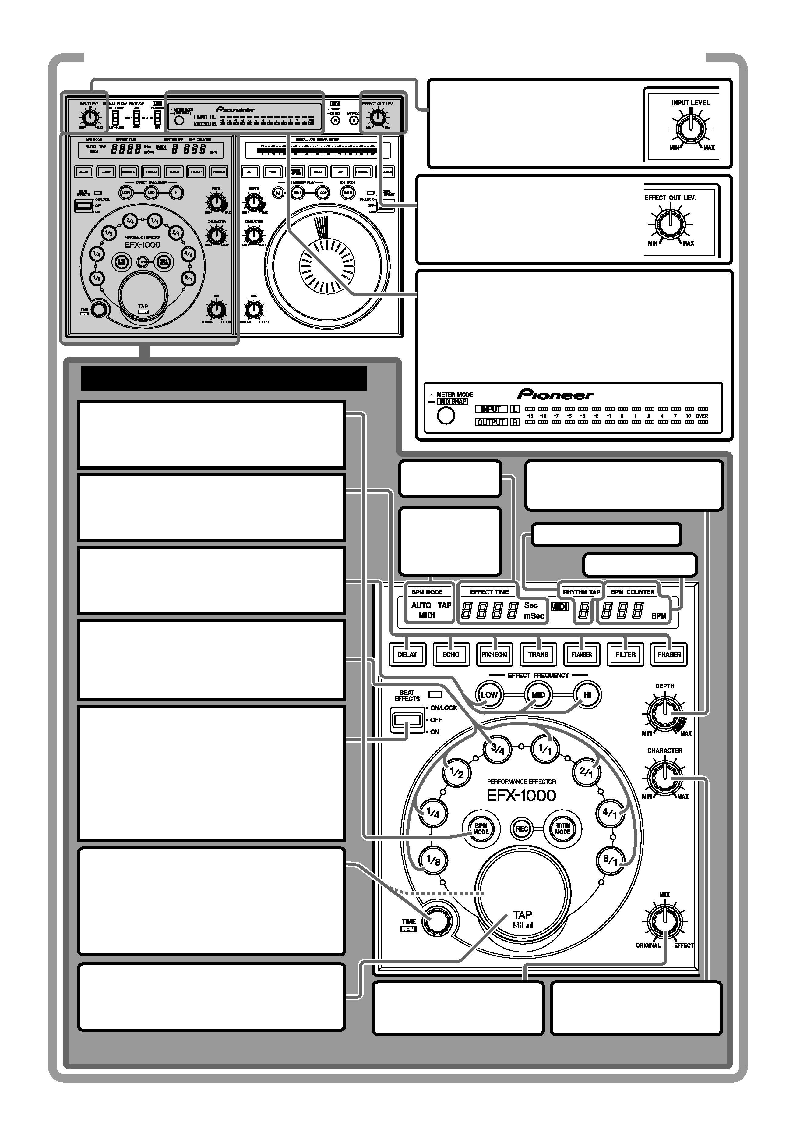
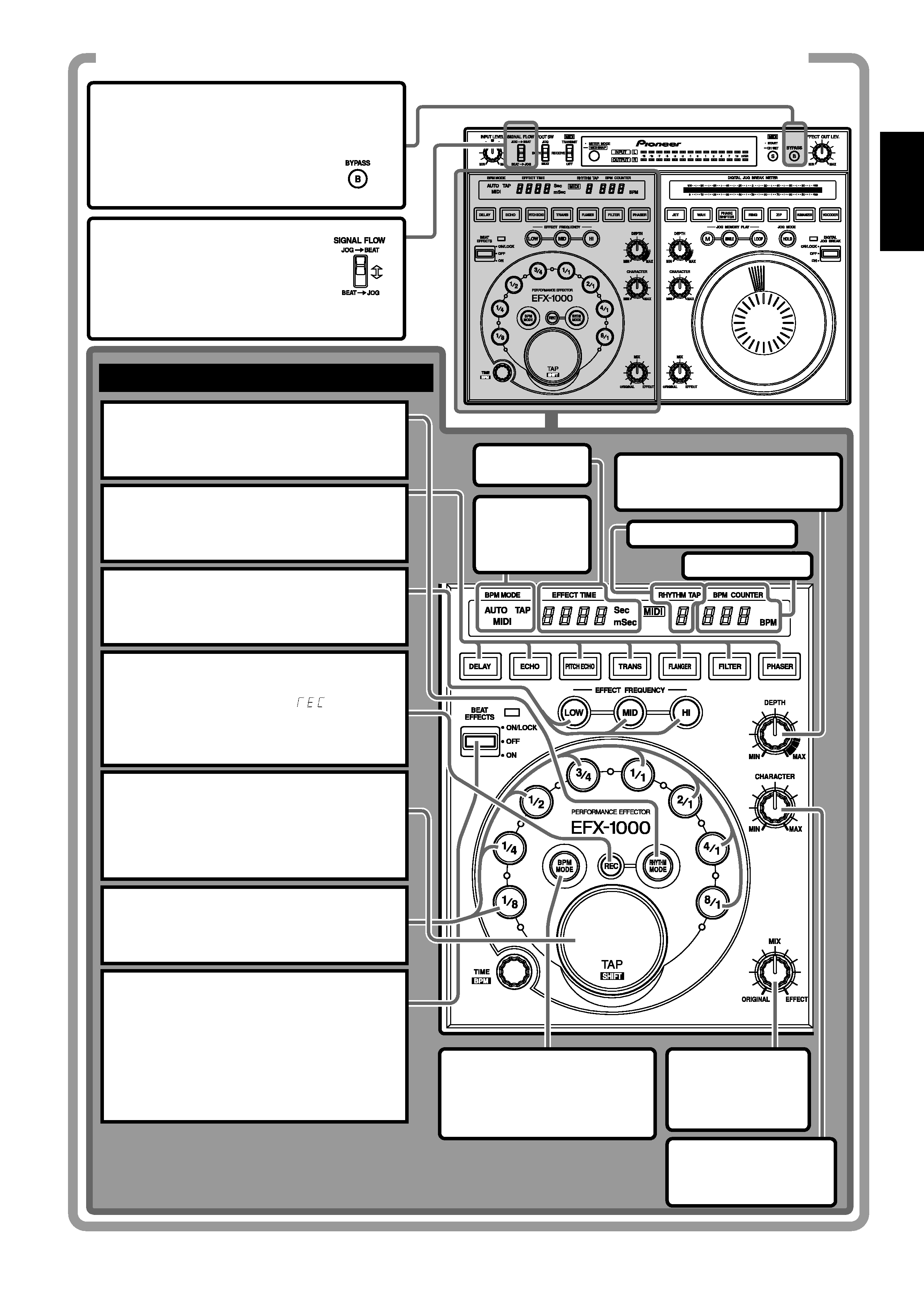
QUICK OPERATION GUIDE (1/3)
USING BEAT EFFECTS [BPM MODE]
Adjusting effect output level
Rotate the EFFECT OUT LEV. dial to
adjust the effect output level.
Changing the level meter display mode
Each time the METER MODE button is pressed, the
level meter display alternates as follows:
÷ INPUT, OUTPUT light: Input and output monaural
display.
÷ INPUT, L, R light: Input stereo display.
÷ OUTPUT, L, R light: Output stereo display.
Adjusting the input level
Input
signals
to
the
input
connectors,
and
adjust
the
INPUT LEVEL dial.
1. Select the BPM measurement mode.
Press the BPM MODE button so that the
button lights together with the desired mode
indicator (AUTO/MIDI/TAP).
2. Select effect type.
Press the DELAY, ECHO, PITCH ECHO,
TRANS, FLANGER, FILTER or PHASER button
and the pressed button starts to flash.
3. Select the sound range for the effect.
Press the button of the frequency (LOW, MID,
HI) you wish to affect by the beat effect and
the corresponding indicator lights.
4. Select the beat with which the effect is
to be synchronized.
Press a beat select button (1/8, 1/4, 1/2, 3/4,
1/1, 2/1, 4/1 or 8/1) to light the desired button.
5. Apply an effect.
Press the lever towards you (ON position) to
start operation; release it and it returns to
the center position (OFF position). In the
center position (OFF position), the original
sound is not affected. Press the lever away
from you to lock it in position so that the
beat effect is applied also when the lever is
released.
TIME/BPM dial
Set the desired effect time as in step 4.
Turn the TIME/BPM dial while holding down
the TAP/SHIFT button to make the desired
BPM setting. When also the BPM MODE
button is held down, BPM can be set in 0.1
increments.
TAP/SHIFT button
BPM can be manually adjusted by adjusting
the beat (quarter notes) and hitting this key
two times or more.
MIX dial
Adjusts the balance between
the original sound and effects.
CHARACTER dial
Sets the parameter 2 of each
effect.
EFFECT TIME
display
BPM
measurement
mode
indicators
DEPTH dial
Sets the parameter 1 of each
effect.
RHYTHM TAP display
BPM COUNTER
English
5
<DRB1369>
QUICK OPERATION GUIDE (2/3)
BYPASS button
When the button is pressed (button
indicator flashes), the signal entering
the input connectors is output
directly (without modification) to the
output connectors.
SIGNAL FLOW switch
Selects the order in which signals
are passed through the electronic
sections (from beat effect to digital
jog break, or vice versa).
1. Select the rhythm input mode.
Press the RHYTHM MODE button so that the
button indicator lights.
USING BEAT EFFECTS [RHYTHM MODE]
2. Select effect type.
Press the DELAY, ECHO, PITCH ECHO, TRANS,
FLANGER, FILTER or PHASER button and the
pressed button starts to flash.
3. Select the sound range for the effect.
Press the button of the frequency (LOW, MID,
HI) you wish to affect by the rhythm effect and
the corresponding indicator lights.
5. Input the rhythm.
Tap your finger on the TAP button to input the
desired rhythm. As you input the rhythm, the
rhythm will be calculated and displayed on the
RHYTHM TAP display (up to 8 taps with tap
interval of 2 seconds or less).
7. Apply an effect.
Press the lever towards you (ON position) to
start operation; release it and it returns to the
center position (OFF position). In the center
position (OFF position), the original sound is
not affected. Press the lever away from you to
lock it in position so that the rhythm effect is
applied also when the lever is released.
BPM MODE button
When the BPM MODE button is
pressed while in the rhythm
mode, the mode changes to
the beat effect BPM mode.
MIX dial
Adjusts the balance
between the original
sound and effects.
CHARACTER dial
Sets the parameter 2 of
each effect.
EFFECT
TIME display
BPM
measurement
mode
indicators
DEPTH dial
Sets the parameter 1 of each
effect.
RHYTHM TAP display
BPM COUNTER
4. Set to REC mode.
¶ When the REC button is pressed, the
BPM display indicates "
".
¶ If no rhythm has been input, the unit
will automatically enter the REC mode
in step 1.
6. Select the overall rhythm time.
The pressed beat select button will light, and
the overall rhythm time will be set at the
multiple corresponding to the pressed button.