ORDER NO.
PIONEER CORPORATION 4-1, Meguro 1-chome, Meguro-ku, Tokyo 153-8654, Japan
PIONEER ELECTRONICS (USA) INC. P.O. Box 1760, Long Beach, CA 90801-1760, U.S.A.
PIONEER EUROPE NV Haven 1087, Keetberglaan 1, 9120 Melsele, Belgium
PIONEER ELECTRONICS ASIACENTRE PTE. LTD. 253 Alexandra Road, #04-01, Singapore 159936
PIONEER CORPORATION 2004
PULL-OPEN
STANDBY/ON
DVD
HDD
OPEN/CLOSE
REC ONE TOUCH COPY
DV IN/OUT
DVR-520H-S
RRV2979
DVD RECORDER
DVR-520H-S
DVR-720H-S
THIS MANUAL IS APPLICABLE TO THE FOLLOWING MODEL(S) AND TYPE(S).
Model
Type
Power Requirement
Region No.
Serial No.
Please confirm 3rd & 4th
alphabetical letters.
DVR-520H-S
WYXK
AC220-240V
2
&&UK######$$
DVR-520H-S
WYXU
AC220-240V
2
&&PG######$$
DVR-520H-S
WVXK
AC220-240V
2
&&UK######$$
DVR-720H-S
WYXK
AC220-240V
2
&&UK######$$
DVR-720H-S
WVXK
AC220-240V
2
&&UK######$$
÷ When servicing this model, some service procedures may reset the settings that customer set (*) to
the factory default settings. Make sure to explain this to the customer.
(*) : Initial Setup (Clock Setting, Remote Control Set, Channel settings, Video Out settings,
Audio In settings, Audio Out settings, Language settings)
Refer to the chapter 13 of the Operating Instructions for more details.
An HDD (Hard Disc Drive) is mounted in this product.
The HDD is a precision instrument very vulnerable to shock and electrostatic charges. Please read
"7.4 Cautions on Handling the HDD" in this manual and exercise sufficient caution when handling the
HDD itself, as well as the product with the HDD built in.
When an HDD becomes defective and inoperable, restoration of the user's data recorded on the HDD,
or copying of the user's recorded data to other media (such as a new HDD) is totally impossible.
Before servicing, OBTAIN THE USER'S PRIOR CONSENT to that effect.
The user must be made aware that all recorded data are deleted if the HDD is intialized.
For details, refer to "Important symbols for good services" .
T-ZZV JUNE 2004 printed in Japan
DVR-520H-S
2
12
34
12
3
4
C
D
F
A
B
E
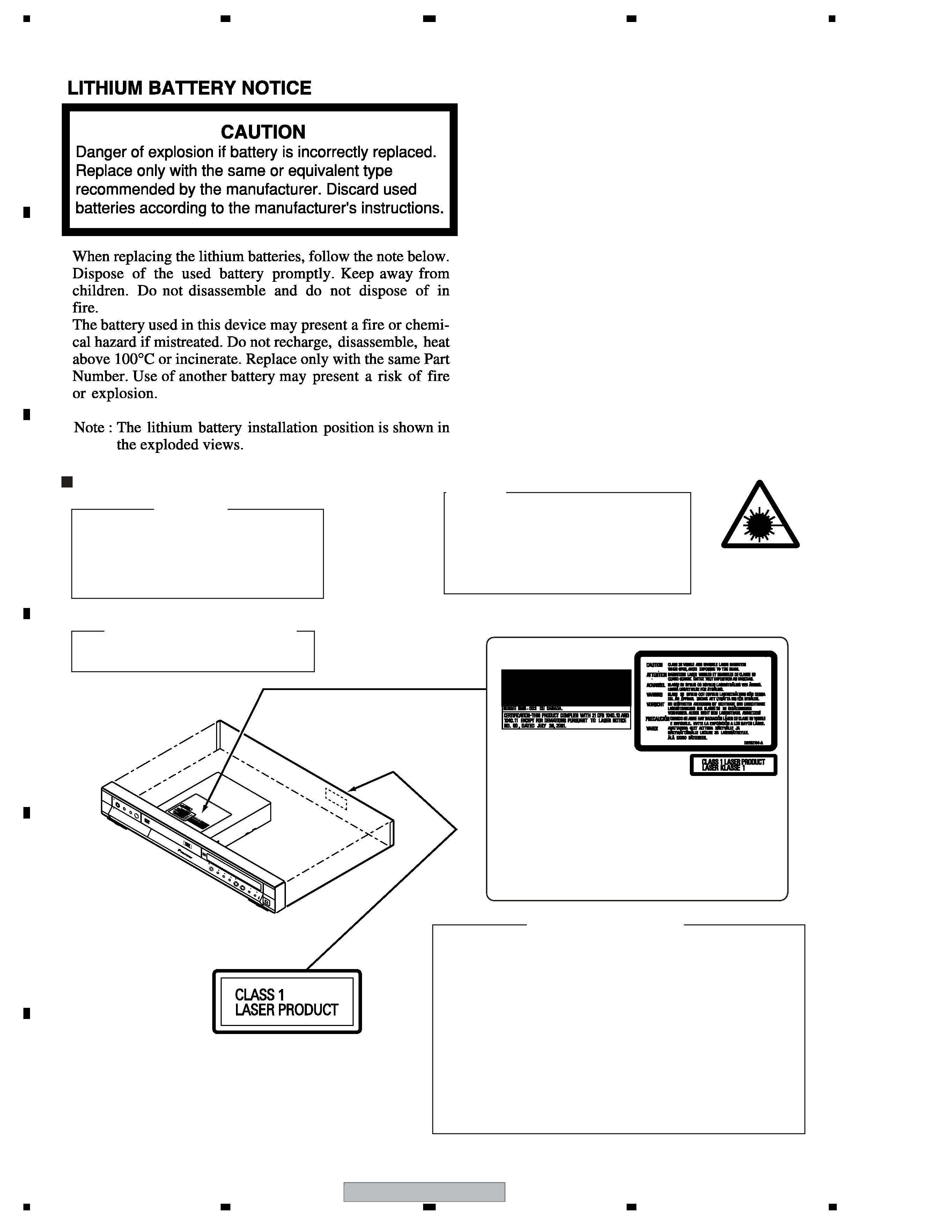
SAFETY INFORMATION
WARNING!
DEVICE INCLUDES LASER DIODE WHICH
EMITS INVISIBLE INFRARED RADIATION
WHICH IS DANGEROUS TO EYES. THERE IS
A WARNING SIGN ACCORDING TO PICTURE
1 INSIDE THE DEVICE CLOSE TO THE LASER
DIODE.
LASER
Picture 1
Warning sign for
laser radiation
LABEL CHECK
LASER DIODE CHARACTERISTICS
MAXIMUM OUTPUT POWER : 70 mw
WAVELENGTH : 658 nm
IMPORTANT
THIS PIONEER APPARATUS CONTAINS
LASER OF CLASS 1.
SERVICING OPERATION OF THE APPARATUS
SHOULD BE DONE BY A SPECIALLY
INSTRUCTED PERSON.
PUL
L-O
PEN
STA
NDB
Y/O
N
DV
D
HD
D
OPEN/CLOS
E
RE
C
ONE
TO
UC
H CO
PY
DV
IN/O
UT
Î
CLAMP signals for detecting the loading state are detected
by the drive CPUs, and the design prevents laser diode
oscillation when the CLAMP signal turns OFF.
In normal operation, if no disc is clamped, the laser diode
oscillation is disabled.
However, the interlock does not always operate in the test
mode.
2. When the cover is opened, close viewing of the objective
lens with the naked eye will cause exposure to a Class 3A
laser beam.
Additional Laser Caution
1. The ON/OFF(ON:low level,OFF:high level) status of the
DRW2194
DVR-520H-S
3
56
78
56
7
8
C
D
F
A
B
E
[ Important symbols for good services ]
In this manual, the symbols shown-below indicate that adjustments, settings or cleaning should be made securely.
When you find the procedures bearing any of the symbols, be sure to fulfill them:
2. Adjustments
To keep the original performances of the product, optimum adjustments or specification confirmation is indispensable.
In accordance with the procedures or instructions described in this manual, adjustments should be performed.
3. Cleaning
For optical pickups, tape-deck heads, lenses and mirrors used in projection monitors, and other parts requiring cleaning,
proper cleaning should be performed to restore their performances.
5. Lubricants, glues, and replacement parts
Appropriately applying grease or glue can maintain the product performances. But improper lubrication or applying
glue may lead to failures or troubles in the product. By following the instructions in this manual, be sure to apply the
prescribed grease or glue to proper portions by the appropriate amount.For replacement parts or tools, the prescribed
ones should be used.
4. Shipping mode and shipping screws
To protect the product from damages or failures that may be caused during transit, the shipping mode should be set or
the shipping screws should be installed before shipping out in accordance with this manual, if necessary.
1. Product safety
You should conform to the regulations governing the product (safety, radio and noise, and other regulations), and
should keep the safety during servicing by following the safety instructions described in this manual.

DVR-520H-S
4
12
34
12
3
4
C
D
F
A
B
E
CONTENTS
SAFETY INFORMATION ..................................................................................................................................... 2
1. SPECIFICATIONS ............................................................................................................................................ 5
2. EXPLODED VIEWS AND PARTS LIST ............................................................................................................ 8
2.1 PACKING ................................................................................................................................................... 8
2.2 EXTERIOR............................................................................................................................................... 10
2.3 FRONT PANEL ........................................................................................................................................ 12
3. BLOCK DIAGRAM AND SCHEMATIC DIAGRAM ..........................................................................................14
3.1.1 OVERALL BLOCK DIAGRAM............................................................................................................... 14
3.1.2 TUNB and JCKB ASSY BLOCK DIAGRAM..........................................................................................16
3.1.3 MAIN ASSY BLOCK DIAGRAM............................................................................................................ 18
3.1.4 POWER BLOCK DIAGRAM.................................................................................................................. 20
3.2 OVERALL WIRING DIAGRAM................................................................................................................. 22
3.3 TUNB ASSY ............................................................................................................................................. 24
3.4 JCKB ASSY(1/3) ...................................................................................................................................... 26
3.5 JCKB(2/3), ATWB and ATHB ASSYS ...................................................................................................... 28
3.6 JCKB ASSY(3/3) ...................................................................................................................................... 30
3.7 MAIN ASSY(1/5) ...................................................................................................................................... 32
3.8 MAIN ASSY(2/5) ...................................................................................................................................... 34
3.9 MAIN ASSY(3/5) ...................................................................................................................................... 36
3.10 MAIN ASSY(4/5) .................................................................................................................................... 38
3.11 MAIN ASSY(5/5) .................................................................................................................................... 40
3.12 FLKY, KIRB, FRJB and DVJB ASSYS ................................................................................................... 42
3.13 SDEB ASSY........................................................................................................................................... 44
3.14 POWER SUPPLY UNIT.......................................................................................................................... 46
3.15 WAVE FORMS ....................................................................................................................................... 48
4. PCB CONNECTION DIAGRAM ..................................................................................................................... 51
4.1 TUNB ASSY ............................................................................................................................................. 52
4.2 JCKB, ATWB and ATHB ASSYS.............................................................................................................. 54
4.3 MAIN ASSY ............................................................................................................................................. 58
4.4 FLKY, KIRB, FRJB and DVJB ASSYS ..................................................................................................... 62
4.5 SDEB ASSY............................................................................................................................................. 66
4.6 POWER SUPPLY UNIT............................................................................................................................ 68
5. PCB PARTS LIST ........................................................................................................................................... 69
6. ADJUSTMENT ............................................................................................................................................... 74
6.1 TUNB ASSY ADJUSTMENT.................................................................................................................... 74
6.2 MAIN ASSY ADJUSTMENT .................................................................................................................... 75
7. GENERAL INFORMATION ............................................................................................................................. 76
7.1 DIAGNOSIS ............................................................................................................................................. 76
7.1.1 CPRM ID NUMBER AND DATA SETTING............................................................................................ 77
7.1.2 MODEL SETTING................................................................................................................................. 81
7.1.3 DOWNLOAD METHOD ........................................................................................................................ 82
7.1.4 SERVICE MODE................................................................................................................................... 84
7.1.5 DV DEBUG MODE................................................................................................................................ 96
7.1.6 ERROR RATE MEASUREMENT .......................................................................................................... 99
7.1.7 VIDEO ADJUSTMENT FOR SPECIFIC AREA ................................................................................... 101
7.1.8 AGING MODE..................................................................................................................................... 105
7.1.9 SETUP SEQUENCE ........................................................................................................................... 107
7.1.10 DISASSEMBLY ................................................................................................................................. 108
7.2 IC ........................................................................................................................................................... 113
7.3 OUTLINE OF THE PRODUCT............................................................................................................... 144
7.4 CAUTIONS ON HANDLING THE HDD .................................................................................................. 147
7.5 DISC/CONTENT FORMAT .................................................................................................................... 149
7.6 CLEANING............................................................................................................................................. 150
8. PANEL FACILITIES ...................................................................................................................................... 151

DVR-520H-S
5
56
78
56
7
8
C
D
F
A
B
E
1. SPECIFICATIONS
General
System. . . . . . . . . . . . . . . . . . HDD, DVD-Video,DVD-R/RW,
Video-CD, Super VCD, CD,
CD-R/RW (WMA, MP3, JPEG, CD-DA)
Power requirements. . . . . . . . . . . . . . .220240 V, 50/60 Hz
Power consumption
DVR-520H . . . . . . . . . . . . . . . . . . . . . . . . . . . . . . . . 54 W
DVR-720H . . . . . . . . . . . . . . . . . . . . . . . . . . . . . . . . 56 W
Power consumption in standby mode
0.68 W
(Front panel display: off)
Weight . . . . . . . . . . . . . . . . . . . . . . . . . . . . . . . . . . . . 4.7 kg
Dimensions . . . . . . . . . . . . . 420 (W) x 59 (H) x 339 (D) mm
Operating temperature . . . . . . . . . . . . . . . . . +5
°C to +35°C
Operating humidity . . . . . . . . . . . . . . . . . . . . . . . 5%to 85%
(no condensation)
TV system. . . . . . . . . . . . . . . . . . . . . . . . . . . . PAL/SECAM/
NTSC (external input only)
Recording
Recording format . . . . . . . . . . . . . . . DVD Video Recording
DVD-VIDEO
Recordable discs
DVD-RW (DVD Re-recordable disc)
DVD-R (DVD Recordable disc)
Video recording format
Sampling frequency . . . . . . . . . . . . . . . . . . . . . . . . 13.5MHz
Compression format. . . . . . . . . . . . . . . . . . . . . . . . . . MPEG
Audio recording format
Sampling frequency . . . . . . . . . . . . . . . . . . . . . . . . . . 48kHz
Compression format . . . . . . . . . Dolby Digital or Linear PCM
(uncompressed)
Recording time
HDD
DVR-720H / DVR-520H
Fine (FINE). . . . . . . . . . . . . . . . . . . . . Approx. 34 / 17 hours
Standard Play (SP). . . . . . . . . . . . . . Approx. 68 / 34 hours
Long Play (LP). . . . . . . . . . . . . . . . . Approx. 136 / 68 hours
Extended Play (EP). . . . . . . . . . . . Approx. 204 / 102 hours
Manual Mode (MN) . . . . . . Approx. 34204 / 17102 hours
DVD-R/DVD-RW
Fine (FINE). . . . . . . . . . . . . . . . . . . . . . . . . . Approx. 1 hour
Standard Play (SP). . . . . . . . . . . . . . . . . . . .Approx. 2 hours
Long Play (LP). . . . . . . . . . . . . . . . . . . . . . Approx. 4 hours
Extended Play (EP). . . . . . . . . . . . . . . . . . Approx. 6 hours
Manual Mode (MN) . . . . . . . . . . . . . . . . Approx. 16 hours
Tuner
Receivable channels
Timer
Programs . . . . . . . . . . . . . . . . . . . . . . 1 month/32 programs
Clock . . . . . . . . . . . . . . .Quartz lock (24-hour digital display)
Power off memory . . . . Approx. 5 years (after manufacture)
Input/Output
VHF/UHF antenna input/output terminal . . . . VHF/UHF set
75
(IEC connector)
Video input . . . . . . . . . . . . . . . . . . . . Input 1 (rear), 2 (front)
Input level . . . . . . . . . . . . . . . . . . . . . . . . . . .1 Vp-p (75
)
Jacks . . . . . . . . . . . . . . . . . . . . . . AV connector 2 (Input 1),
RCA jack (Input 2)
Video output. . . . . . . . . . . . . . . . . . . . . . . . . . . AV1 Output
Output level. . . . . . . . . . . . . . . . . . . . . . . . . .1 Vp-p (75
)
Jacks . . . . . . . . . . . . . . . . . . . . . . . . AV connector 1 (AV1)
RCA jack (Output)
S-Video input . . . . . . . . . . . . . . . . . . Input 1 (rear), 2 (front)
Y (luminance) - Input level. . . . . . . . . . . . . . .1 Vp-p (75
)
C (colour) - Input level . . . . . . . . . . . . . . 286 mVp-p (75
)
Jacks . . . . . . . . . . . . . . . . . . . . . . .AV connector 2 (Input 1),
4 pin mini DIN (Input 2)
S-Video output. . . . . . . . . . . . . . . . . . . . . . . . . AV1 / Output
Y (luminance) - Output level . . . . . . . . . . . . . .1 Vp-p (75
)
C (colour) - Output level. . . . . . . . . . . . . .286 mVp-p (75
)
Jacks . . . . . . . . . . . . . . . . . . . . . . . . AV connector 1 (AV1),
4 pin mini DIN (Output)
RGB input
Input level . . . . . . . . . . . . . . . . . . . . . . . . . 0.7 Vp-p (75
)
Jacks . . . . . . . . . . . . . . . . . . . . . . AV connector 2 (Input 1)
RGB output
Output level. . . . . . . . . . . . . . . . . . . . . . . . . 0.7 Vp-p (75
)
Jacks . . . . . . . . . . . . . . . . . . . . . . . . AV connector 1 (AV1)
VHF (low)
VHF (high)
Hyper
UHF
VHF (low)
VHF (high)
Hyper
UHF
STEREO
B/G - A2
I - NICAM
L - NICAM
B/G - NICAM
D/K - NICAM
Channel
E2 - E4
X - Z
E5 - E12
S1 - S20
M1 - M10
U1 - U10
S21 - S41
E21 - E69
Frequency
47 - 89 MHz
104 - 300 MHz
302 - 470 MHz
470 - 862 MHz
Channel
A - C
X - Z
D - J
11, 13
S1 - S20
S21 - S41
E21 - E69
Frequency
44 - 89 MHz
104 - 300 MHz
302 - 470 MHz
470 - 862 MHz
PAL B/G
PAL I
Channel
2 - 4
5 - 10
B - Q
S21 - S41
21 - 69
Frequency
49 - 65 MHz
104 - 300 MHz
300 - 470 MHz
470 - 862 MHz
Channel
R1 - R5
R6 - R12
S1 - S20
S21 - S41
E21 - E69
Frequency
49 - 94 MHz
104 - 300 MHz
302 - 470 MHz
470 - 862 MHz
SECAM L
SECAM D/K