ORDER NO.
PIONEER ELECTRONIC CORPORATION 4-1, Meguro 1-Chome, Meguro-ku, Tokyo 153-8654, Japan
PIONEER ELECTRONICS SERVICE, INC. P.O. Box 1760, Long Beach, CA 90801-1760, U.S.A.
PIONEER ELECTRONIC (EUROPE) N.V. Haven 1087, Keetberglaan 1, 9120 Melsele, Belgium
PIONEER ELECTRONICS ASIACENTRE PTE. LTD. 253 Alexandra Road, #04-01, Singapore 159936
PIONEER ELECTRONIC CORPORATION 1999
c
DV-K101 (1)
RRV2088
T IZE JAN. 1999 Printed in Japan
DVD PLAYER
1. SAFETY INFORMATION ...................................... 2
2. EXPLODED VIEWS AND PARTS LIST ................ 3
3. SCHEMATIC DIAGRAM ..................................... 10
4. PCB CONNECTION DIAGRAM .......................... 25
5. PCB PARTS LIST ............................................... 35
6. ADJUSTMENT .................................................... 40
CONTENTS
7. GENERAL INFORMATION ................................ 42
7.1 IC .................................................................. 42
7.2 DISASSEMBLY ............................................ 46
7.3 BLOCK DIAGRAM ........................................ 47
8. PANEL FACILITIES AND SPECIFICATIONS .... 48
Refer to the service guide RRV2004 for DV-515.
DVD PLAYER
DV-K101
1
2
3
4
5
6
7
8
9
0
+10
PLAYBACK ONE-TOUCH
KARAOKE
CONTROL
KARAOKE
MODE
ON/OFF
OPEN/CLOSE
STANDBY
MIN
MAX
MIN
MAX
MIN
MAX
MIC CONTROL
PREVIOUS
NEXT
RETURN
SELECT
STOP
PLAY
PAUSE
STANDBY/ ON
LOW CONTROL HIGH
KEY
ECHO
MIC 1
MIC 2
MIC 1
MIC 2
DIGITAL VIDEO
MC
Type
Model
Power Requirement
Region No.
DV-K101 (1)
RL/2
AC110-127V / 220-240V
Automatic select
3
RAM/2
AC110-127V / 220-240V
Automatic select
6
THIS MANUAL IS APPLICABLE TO THE FOLLOWING MODEL(S) AND TYPE(S).
The Voltage can be converted by the
following method.
DV-K101 has two models which specifications are different.
Each distinction will be confirmed with the indication of
the rear panel. Refer to the following service manuals.
Indication of Rear Panel
Service Manual No.
DV-K101
RRV1942
DV-K101 (1)
RRV2088 (this manual)
2
DV-K101 (1)
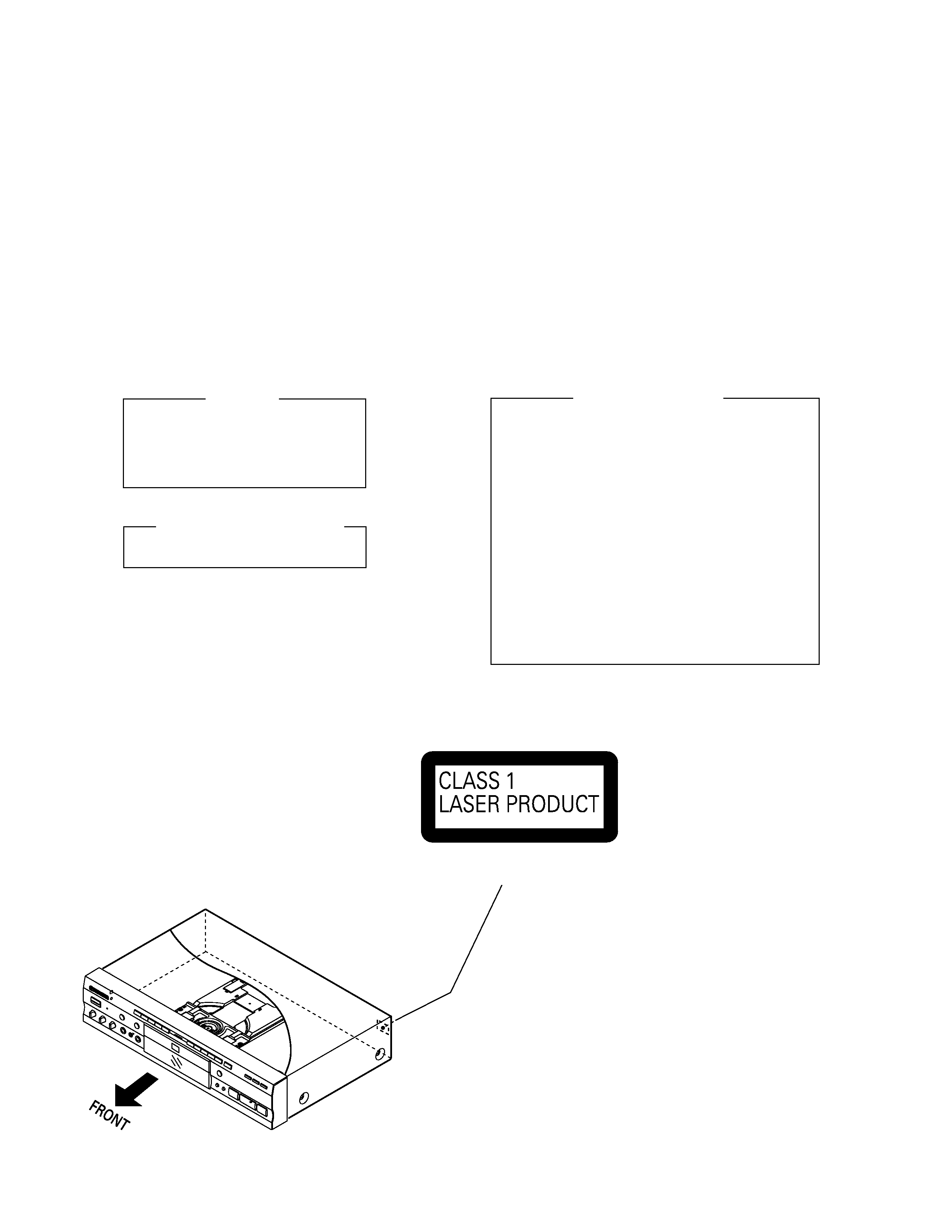
LABEL CHECK
IMPORTANT
THIS PIONEER APPARATUS CONTAINS
LASER OF CLASS 1.
SERVICING OPERATION OF THE APPARATUS
SHOULD BE DONE BY A SPECIALLY
INSTRUCTED PERSON.
LASER DIODE CHARACTERISTICS
MAXIMUM OUTPUT POWER : 7 mW
WAVELENGTH : 650 nm
Additional Laser Caution
1. Inside detection switch (S201 on the INSB assy) and loading-
status detection switch (S301 on the LOSB assy) are detected
by the microprocessor (IC501 in the DVDM assy).
· To permit the laser diode to oscillate, it is required to set the
inside detection switch for the inside position (S201 : ON) and to
set the loading-status detection switch for the clamp position (the
center terminal of S301 is shorted to +5V). The laser diode
oscillation will continue if pin 13 of IC101 is shorted to +5V (fault
condition) in the DVDM assy.
In the test mode
, the laser diode oscillates when microproces-
sor detects a PLAY signal, or when the PLAY key is pressed
(S106 ON in the FLKY assy), with the above requirements satis-
fied.
2. When the cover is open, close viewing through the objective lens
with the naked eye will cause exposure to the laser beam.
: Refer to the service guide RRV2004.
(Printed on the Rear Panel)
1. SAFETY INFORMATION
This service manual is intended for qualified service technicians ; it is not meant for the casual do-it-
yourselfer. Qualified technicians have the necessary test equipment and tools, and have been trained
to properly and safely repair complex products such as those covered by this manual.
Improperly performed repairs can adversely affect the safety and reliability of the product and may
void the warranty. If you are not qualified to perform the repair of this product properly and safely, you
should not risk trying to do so and refer the repair to a qualified service technician.
WARNING
This product contains lead in solder and certain electrical parts contain chemicals which are known to the state of California to cause
cancer, birth defects or other reproductive harm.
Health & Safety Code Section 25249.6 Proposition 65
DV-K101 (1)
3
Mark No.
Symbol and Description
Part No.
Remarks
RL/2 Type
RAM/2 Type
1
Power Cord
ADG1127
ADG7017
6
Operating Instructions (Trad-Chinese)
VRC1087
Not used
6
Operating Instructions (Simp-Chinese)
Not used
VRC1086
NSP
7
Regular User's Card
Not used
VRY1112
14
Packing Case
VHG1751
VHG1741
NSP
15
Warranty Card PJ
Not used
ARY7029
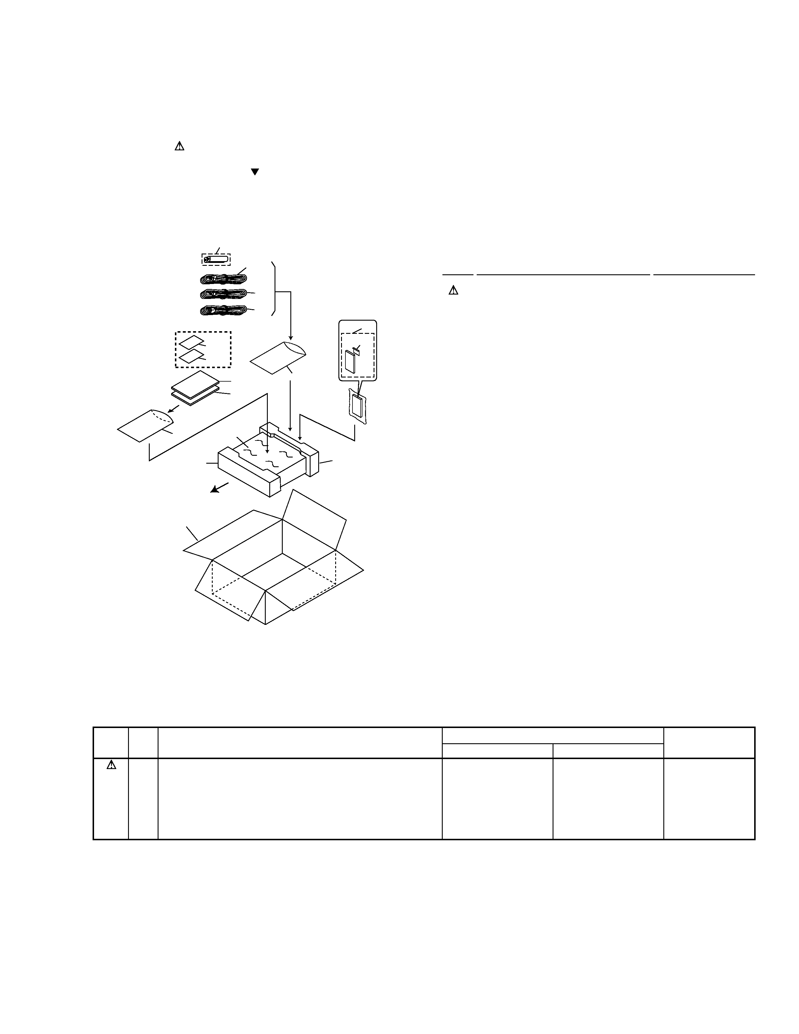
(1) PACKING PARTS LIST
1
Power Cord
See Contrast table (2)
2
Video Cord (L=1.5m)
VDE1048
3
Audio Cord (L=1.5m)
VDE1033
NSP
4
Dry Cell Battery (R6P, AA)
VEM-013
5
Operating Instructions
VRB1213
(English)
6
Operating Instructions
See Contrast table (2)
NSP
7
Regular User's Card
See Contrast table (2)
8
Polyethylene Bag
Z21-038
(230
×340×0.03)
9
Remote Control Unit
VXX2576
(CU-DV020)
10
Battery Cover
VNK3703
11
Pad F
VHA1220
12
Pad R
VHA1221
13
Mirror Mat Sheet
Z23-007
(750
×600×0.5)
14
Packing Case
See Contrast table (2)
NSP
15
Warranty Card PJ
See Contrast table (2)
2.1 PACKING
2. EXPLODED VIEWS AND PARTS LIST
NOTES:
· Parts marked by "NSP" are generally unavailable because they are not in our Master Spare Parts List.
· The mark found on some component parts indicates the importance of the safety factor of the part.
Therefore, when replacing, be sure to use parts of identical designation.
· Screws adjacent to mark on the product are used for disassembly.
Mark No.
Description
Part No.
FRONT
8
7
6
5
RAM/2 Type Only
15
8
10
9
3
14
4
2
1
11
12
13
(2) CONTRAST TABLE
DV-K101/RL/2 and RAM/2 are constructed the same except for the following :
DV-K101 (1)
4
2
5
4
3
10
11
Refer to
"2.3 FRONT PANEL SECTION".
10
8
9
7
6
11
14
13
12
15
16
1
18
17
RL/2 Type
Only
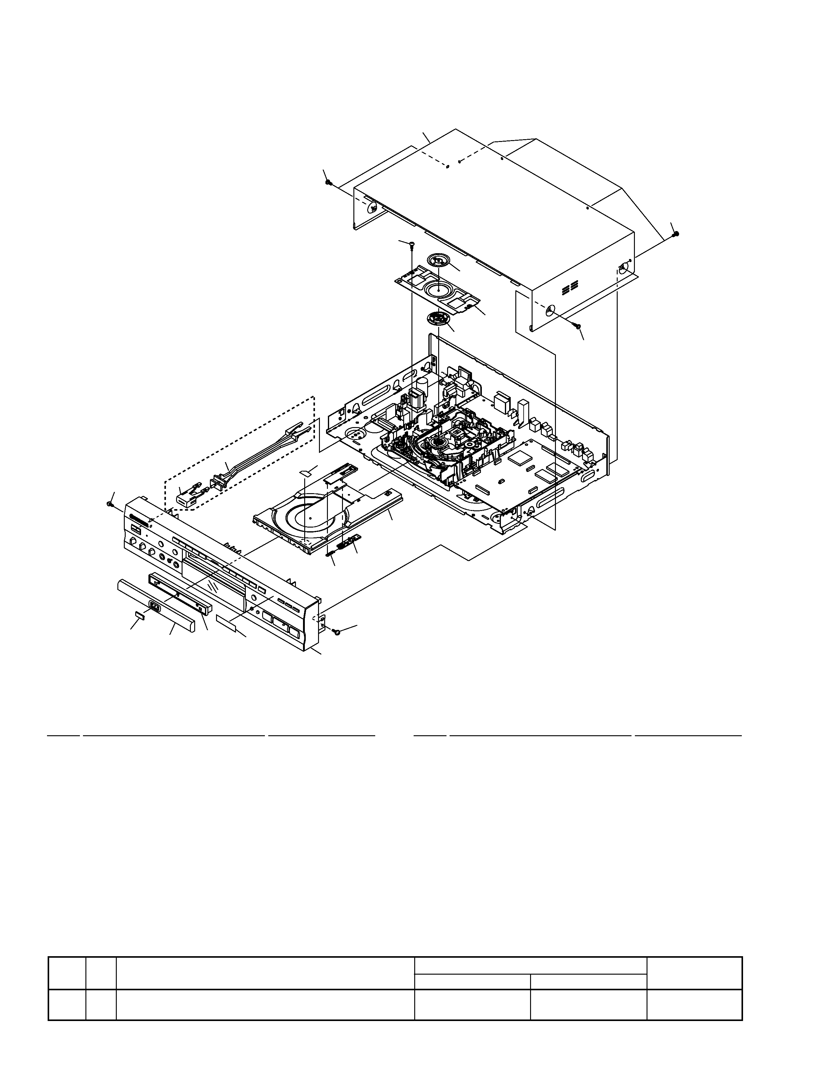
2.2 EXTERIOR SECTION
1
Bonnet Case S
VXX2620
2
Tray Panel
VNK4158
3
DVD Plate
VAM1080
4
Tray Panel Plate
VNK4273
NSP
5
Getter
VRW1730
6
Tray
VNL1731
7
Tray Stopper
VNL1739
8
Spring
VBH1277
9
Tray Label
VRW1628
10
Screw
IBZ30P080FMC
11
Screw
BCZ40P060FNI
12
Clamper Plate
VNE2068
13
Bridge
VNE2069
14
Clamper
VNL1738
15
Screw
BPZ26P080FZK
16
Screw
BBZ30P080FMC
17
Power Button
See Contrast table (2)
18
Power Button Joint
See Contrast table (2)
(1) EXTERIOR SECTION PARTS LIST
Mark No.
Description
Part No.
Mark No.
Description
Part No.
Mark No.
Symbol and Description
Part No.
Remarks
RL/2 Type
RAM/2 Type
17
Power Button
VNK4159
Not used
18
Power Button Joint
VNK4267
Not used
(2) CONTRAST TABLE
DV-K101/RL/2 and RAM/2 are constructed the same except for the following :
DV-K101 (1)
5
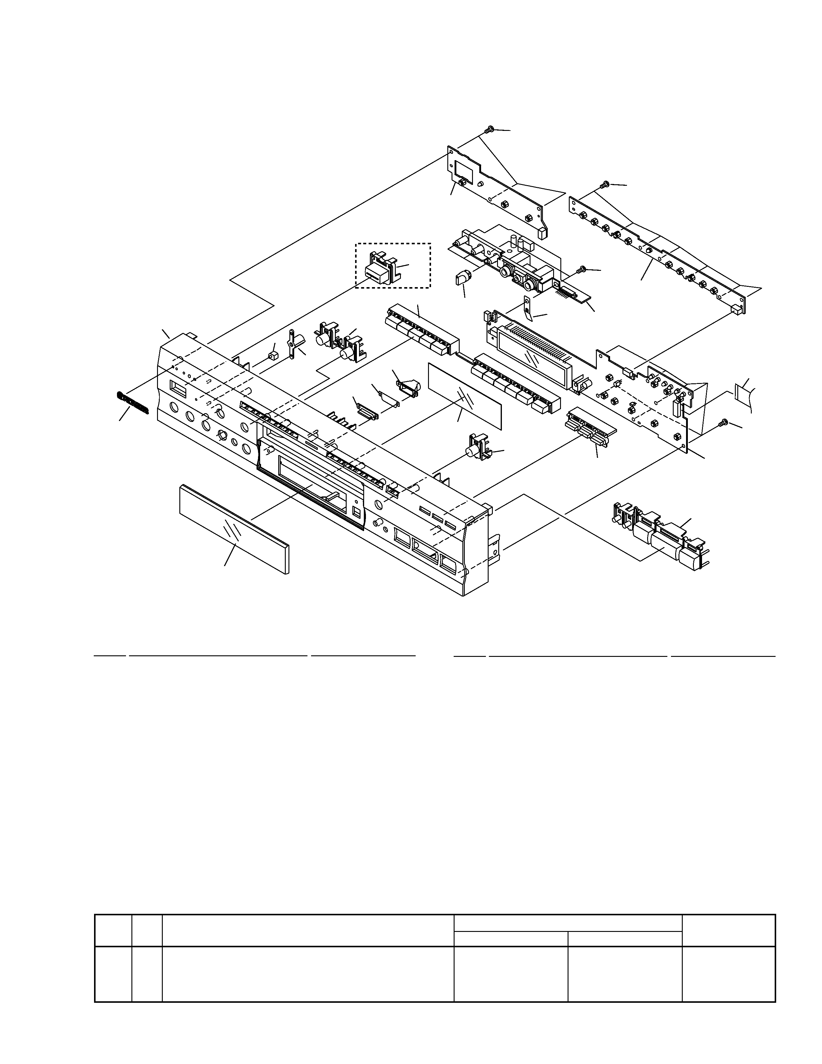
2.3 FRONT PANEL SECTION
1
FLKY Assy
See Contrast table (2)
NSP
2
PWSB Assy
See Contrast table (2)
3
KYLB Assy
VWG2019
4
Front Panel
See Contrast table (2)
5
FL Lens
VNK4272
6
Name Plate
VAM1067
7
LED Lens
PNW2019
8
Main Key
VNK4269
9
11 Key
VNK4271
10
MICB Assy
VWV1664
11
FL Filter
VEC1643
12
Illumination Lens
VNK4264
13
Illumination Filter
VEC1983
14
Illumination Holder
VNK4265
15
Flexible Cable (14P)
VDA1646
(FLKY CN101
DVDM CN602)
16
Screw
BBZ30P080FMC
17
· · · · ·
18
Volume Knob
VNK4279
19
3 Key
VNK4270
20
Light Key
VNK4261
21
Earth Plate
VBK1075
22
Power Button
See Contrast table (2)
23
Lens Holder
VNK4266
(1) FRONT PANEL SECTION PARTS LIST
Mark No.
Description
Part No.
Mark No.
Description
Part No.
Mark No.
Symbol and Description
Part No.
Remarks
RL/2 Type
RAM/2 Type
1
FLKY Assy
VWG2024
VWG2023
NSP
2
PWSB Assy
VWG2021
VWG2020
4
Front Panel
VNK4257
VNK4255
22
Power Button
Not used
VNK4059
(2) CONTRAST TABLE
DV-K101/RL/2 and RAM/2 are constructed the same except for the following :
6
4
7
23
19(1/2)
8
15
3
1
16
10
14
11
13
12
5
16
2
16
9
18
20
16
22
RAM/2 Type Only
21
19(2/2)