ORDER NO.
PIONEER CORPORATION 4-1, Meguro 1-chome, Meguro-ku, Tokyo 153-8654, Japan
PIONEER ELECTRONICS SERVICE, INC. P.O. Box 1760, Long Beach, CA 90801-1760, U.S.A.
PIONEER ELECTRONIC (EUROPE) N.V. Haven 1087, Keetberglaan 1, 9120 Melsele, Belgium
PIONEER ELECTRONICS ASIACENTRE PTE. LTD. 253 Alexandra Road, #04-01, Singapore 159936
PIONEER CORPORATION 2000
c
DVD-V7400
RRV2257
1. SAFETY INFORMATION ....................................... 2
2. EXPLODED VIEWS AND PARTS LIST ................. 4
3. BLOCK DIAGRAM AND SCHEMATIC DIAGRAM .. 10
4. PCB CONNECTION DIAGRAM ........................... 34
5. PCB PARTS LIST ................................................ 45
6. ADJUSTMENT ..................................................... 50
7. GENERAL INFORMATION .................................. 52
7.1 DIAGNOSIS ................................................... 52
7.1.1 TEST MODE SCREEN DISPLAY ............. 52
7.1.2 DISPLAY OF THE ERROR HISTORY ...... 54
CONTENTS
7.1.3 ERROR CODE TABLE ........................... 55
7.1.4 TRAOUBLE SHOOTING .......................... 58
7.1.5 SERIAL CONTROL .................................. 59
7.1.6 PARALLEL CONTROL ............................. 64
7.1.7 DISASSEMBLY ........................................ 67
7.2 PARTS ........................................................... 69
7.2.1 IC ............................................................. 69
8. PANEL FACILITIES AND SPECIFICATIONS .... 78
T ZZY JAN. 2000 Printed in Japan
DVD PLAYER
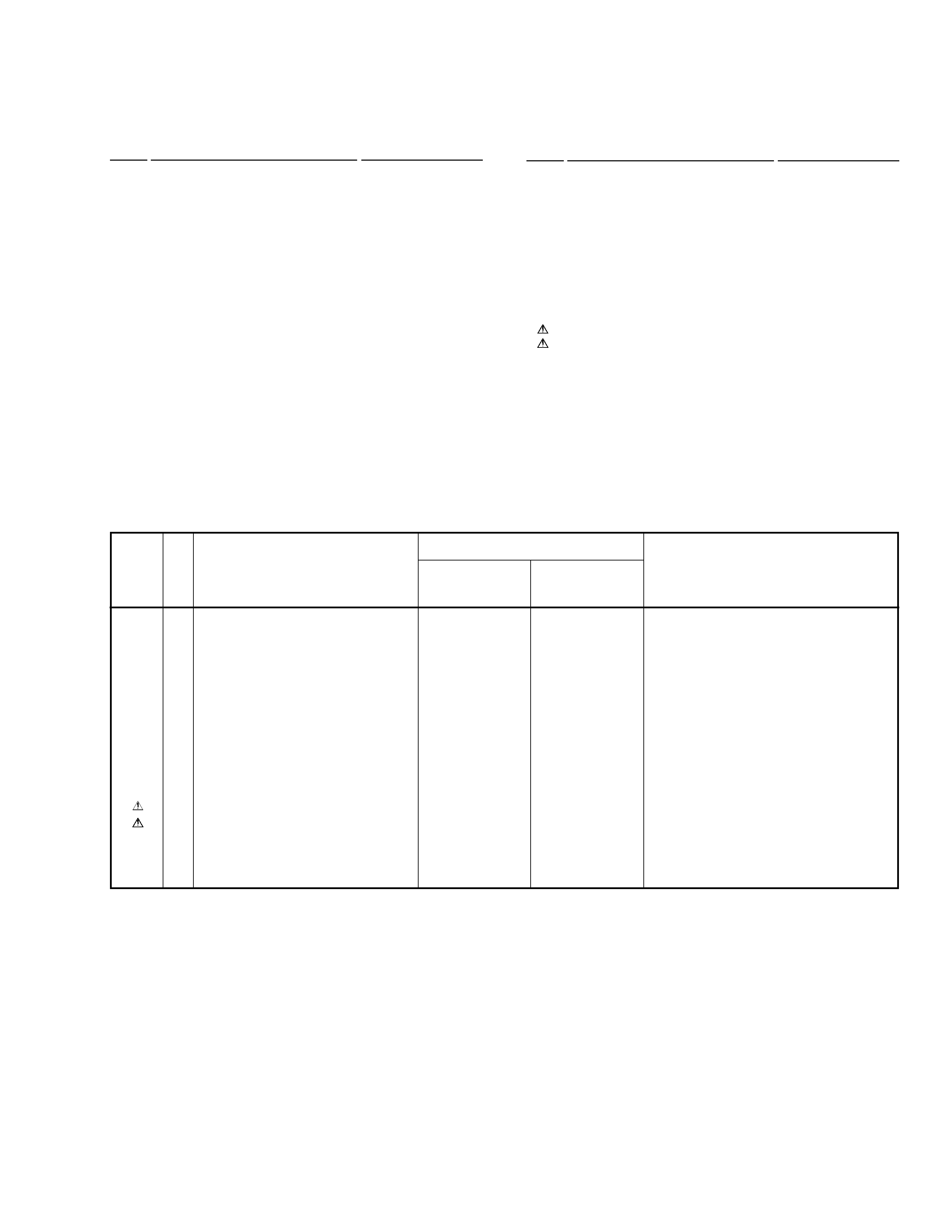
THIS MANUAL IS APPLICABLE TO THE FOLLOWING MODEL(S) AND TYPE(S).
DVD-V7300D
Model
DVD-V7400
DVD-V7300D
Type
Power Requirement
Regional restriction
codes(Region N0.)
KU/CA
O
-
AC120V
1
WYV/RB
-
O
AC-220 - 240V
Automatic select
2
1
4
¡
¢
eE
^
DOLBY
D I G I T A L
SCAN/SKIP
DISPLAY
STILL/STEP
PROGRAM
PLAY/PAUSE
KEY LOCK
NTSC / PAL
STOP
OPEN/CLOSE
DVD PLAYER DVD-V7300D
EXT CONT
LEVEL
MOUSE
/KEY BOARD
PHONES
DVD / CD
Î
STANDBY
ON
MIN
MAX
§
The voltage can be converted
by the following method.
2
DVD-V7400, DVD-V7300D
1. SAFETY INFORMATION
This service manual is intended for qualified service technicians ; it is not meant for the casual do-it-
yourselfer. Qualified technicians have the necessary test equipment and tools, and have been trained
to properly and safely repair complex products such as those covered by this manual.
Improperly performed repairs can adversely affect the safety and reliability of the product and may
void the warranty. If you are not qualified to perform the repair of this product properly and safely, you
should not risk trying to do so and refer the repair to a qualified service technician.
WARNING
This product contains lead in solder and certain electrical parts contain chemicals which are known to the state of California to cause
cancer, birth defects or other reproductive harm.
Health & Safety Code Section 25249.6 Proposition 65
NOTICE
(FOR CANADIAN MODEL ONLY)
Fuse symbols
(fast operating fuse) and/or
(slow operating fuse) on PCB indicate that replacement parts must
be of identical designation.
REMARQUE
(POUR MODÈLE CANADIEN SEULEMENT)
Les symboles de fusible
(fusible de type rapide) et/ou
(fusible de type lent) sur CCI indiquent que les pièces
de remplacement doivent avoir la même désignation.
ANY MEASUREMENTS NOT WITHIN THE LIMITS
OUTLINED ABOVE ARE INDICATIVE OF A POTENTIAL
SHOCK HAZARD AND MUST BE CORRECTED BEFORE
RETURNING THE APPLIANCE TO THE CUSTOMER.
2. PRODUCT SAFETY NOTICE
Many electrical and mechanical parts in the appliance
have special safety related characteristics. These are
often not evident from visual inspection nor the protection
afforded by them necessarily can be obtained by using
replacement components rated for voltage, wattage, etc.
Replacement parts which have these special safety
characteristics are identified in this Service Manual.
Electrical components having such features are identified
by marking with a
on the schematics and on the parts list
in this Service Manual.
The use of a substitute replacement component which does
not have the same safety characteristics as the PIONEER
recommended replacement one, shown in the parts list in
this Service Manual, may create shock, fire, or other hazards.
Product Safety is continuously under review and new
instructions are issued from time to time. For the latest
information, always consult the current PIONEER Service
Manual. A subscription to, or additional copies of, PIONEER
Service Manual may be obtained at a nominal charge from
PIONEER.
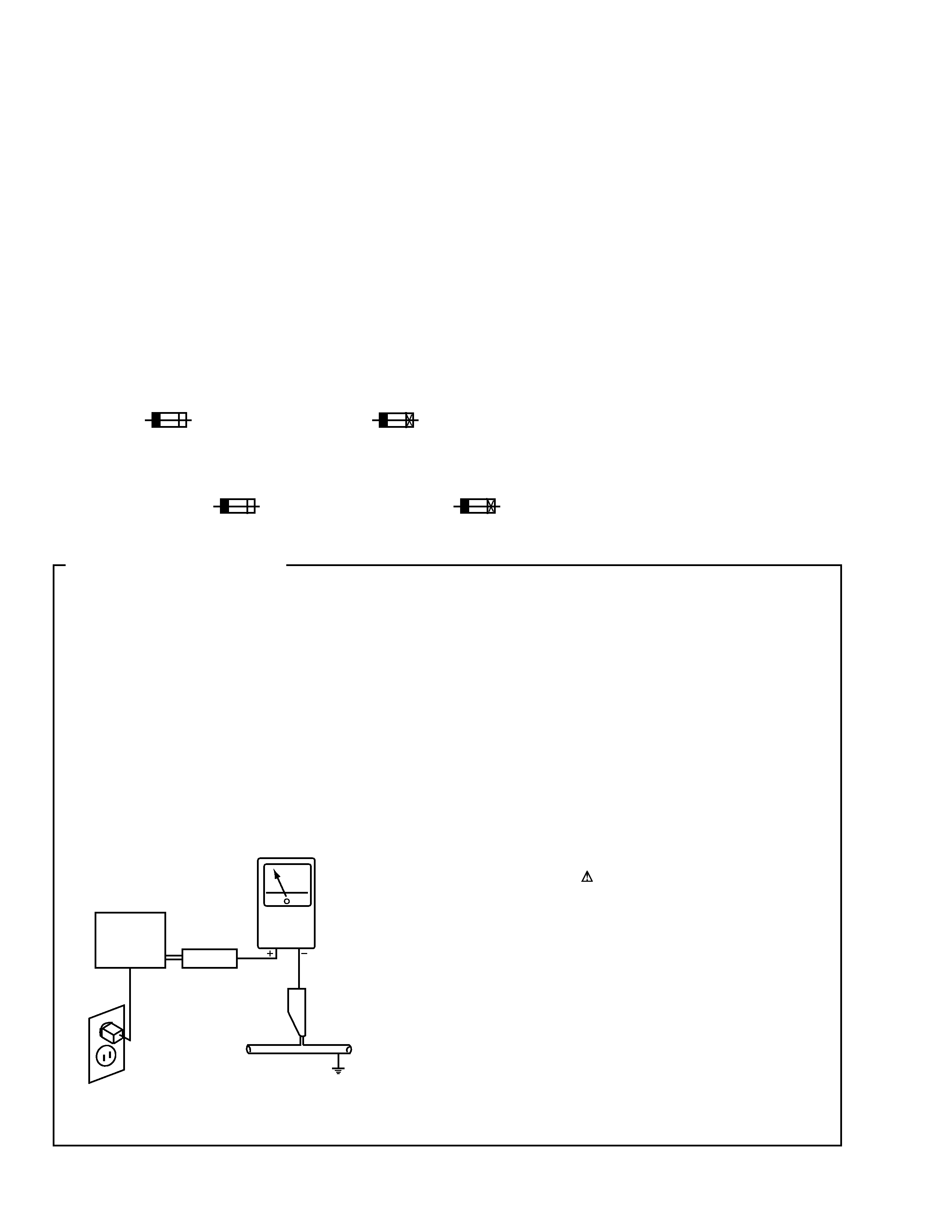
1. SAFETY PRECAUTIONS
The following check should be performed for the
continued protection of the customer and service
technician.
LEAKAGE CURRENT CHECK
Measure leakage current to a known earth ground (water
pipe, conduit, etc.) by connecting a leakage current tester
such as Simpson Model 229-2 or equivalent between the
earth ground and all exposed metal parts of the appliance
(input/output terminals, screwheads, metal overlays, control
shaft, etc.). Plug the AC line cord of the appliance directly
into a 120V AC 60Hz outlet and turn the AC power switch
on. Any current measured must not exceed 0.5mA.
(FOR USA MODEL ONLY)
Leakage
current
tester
Reading should
not be above
0.5mA
Device
under
test
Test all
exposed metal
surfaces
Also test with
plug reversed
(Using AC adapter
plug as required)
Earth
ground
AC Leakage Test
3
DVD-V7400, DVD-V7300D
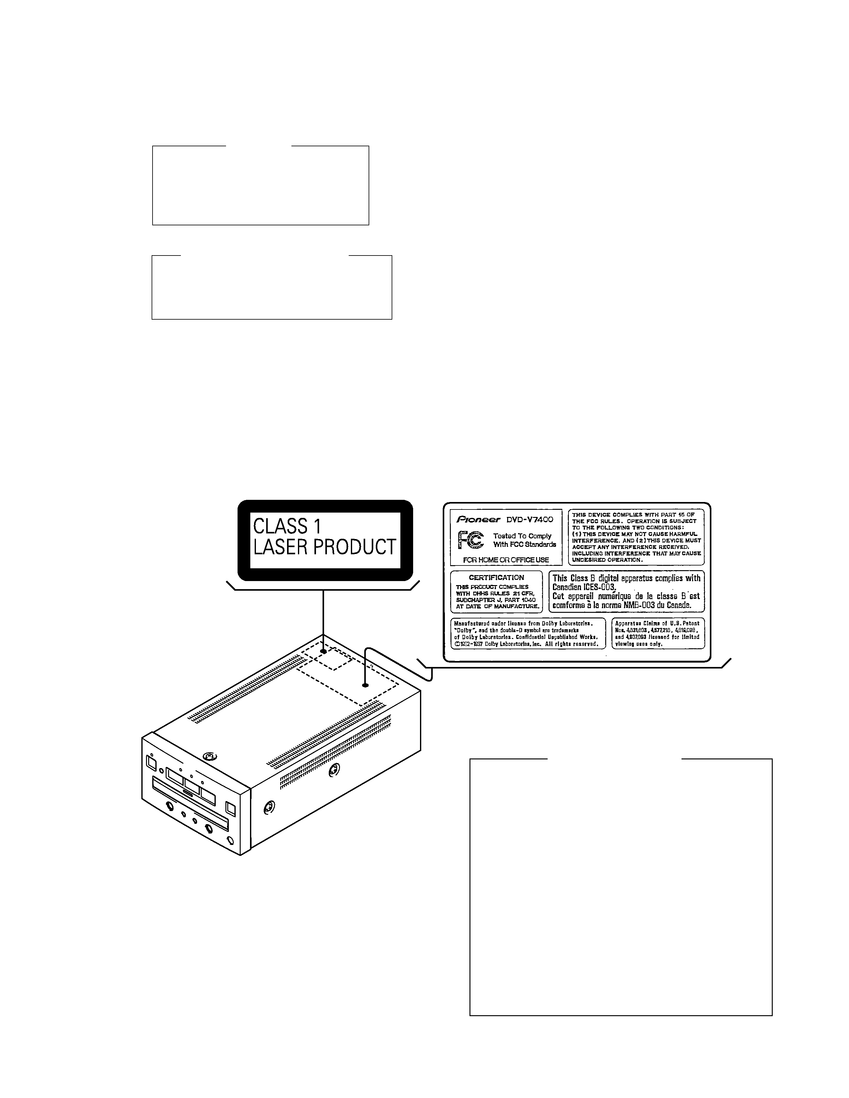
IMPORTANT
THIS PIONEER APPARATUS CONTAINS
LASER OF CLASS 1.
SERVICING OPERATION OF THE APPARATUS
SHOULD BE DONE BY A SPECIALLY
INSTRUCTED PERSON.
LASER DIODE CHARACTERISTICS
FOR DVD : MAXIMUM OUTPUT POWER : 5 mW
WAVELENGTH : 655 nm
FOR CD :
MAXIMUM OUTPUT POWER : 5mW
WAVELENGTH : 785 nm
Additional Laser Caution
1. Inside detection switch (S201 on the SMEB assy) and loading-
status detection switch (S301 on the LOSB assy) are detected
by the microprocessor (IC11 in the DVDM assy).
· To permit the laser diode to oscillate, it is required to set the
inside detection switch for the inside position (S201 : ON) and to
set the loading-status detection switch for the clamp position (the
center terminal of S301 is shorted to +5V). The 655 nm laser
diode for DVD oscillation will continue if pin 19 of IC1 is shorted
to +5V (fault condition) in the DVDM assy.
The 785 nm laser diode for CD oscillates if pin 20 of IC1 is shorted
to +5V in the DVDM assy.
In the test mode
, the laser diode oscillates when microproces-
sor detects a PLAY signal, or when the PLAY key is pressed
(S159 ON in the KEYB assy), with the above requirements satis-
fied.
2. When the cover is open, close viewing through the objective lens
with the naked eye will cause exposure to the laser beam.
: See page 50.
LABEL CHECK
DVD-V7300D/WYV/RB only
DVD-V7400/KU/CA only
DRW1995-A
DRW1986
4
DVD-V7400D, DVD-V7300D
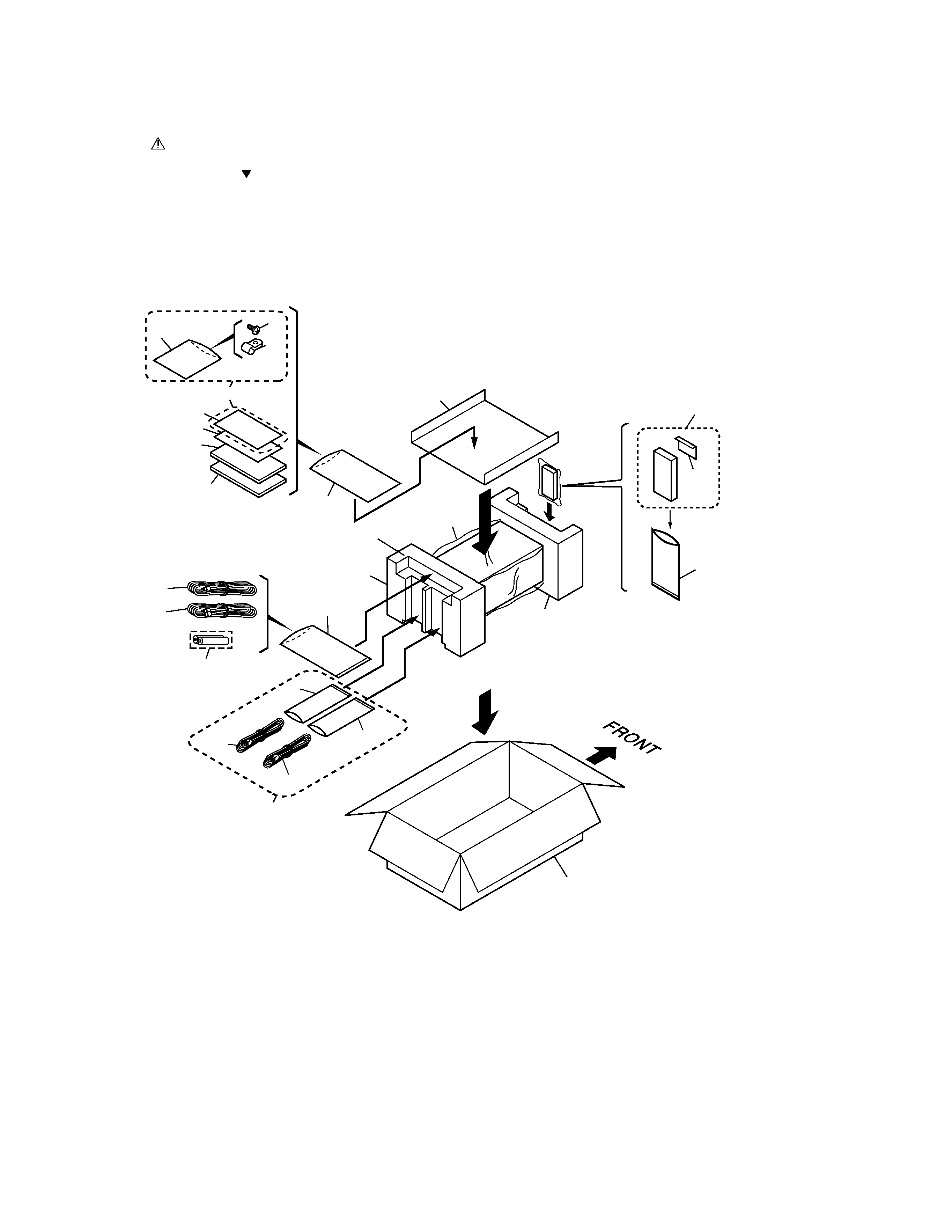
2.1 PACKING
2. EXPLODED VIEWS AND PARTS LIST
NOTES:
· Parts marked by "NSP" are generally unavailable because they are not in our Master Spare Parts List.
· The mark found on some component parts indicates the importance of the safety factor of the part.
Therefore, when replacing, be sure to use parts of identical designation.
· Screws adjacent to mark on the product are used for disassembly.
1
2
7
8
11
16
10
21
5
15
13
12
14
3
4
6
11
17
DVD-V7400/KU/CA only
DVD-V7300D/WYV/RB only
18
9
23
19
20
22
22
5
DVD-V7400, DVD-V7300D
NSP
1
Warranty Card
See Contrast table (2)
2
Bar Code Sheet
VRY1116
3
Audio Cord
VDE1033
4
Video Cord
VDE1048
5
Nylon Clamp
VEC1988
NSP
6
Dry Cell Battery (LR6, AA)
VEM-013
7
Operating Instructions
See Contrast table (2)
(Basic Operations) (English)
8
Operating Instructions
See Contrast table (2)
(Applied Operations) (English)
9
Remote Control Unit
DXX2448
NSP
10
Polyethylene Bag
See Contrast table (2)
(50
×70×0.03)
(1) PACKING PARTS LIST
Mark No.
Description
Part No.
Mark No.
Description
Part No.
11
Polyethylene Bag
Z21-038
(230
×340×0.03)
12
Sheet
RHX1006
NSP
13
Cord Bag
See Contrast table (2)
14
Pad F
VHA1212
15
Pad R
VHA1213
16
Partition Plate
VHB1062
17
Packing Case
See Contrast table (2)
18
Battery Cover
VNK4403
19
AC Power Cord
See Contrast table (2)
20
AC Power Cord
See Contrast table (2)
21
Screw
See Contrast table (2)
22
Cord Bag
See Contrast table (2)
23
Aircap
VHL1048
(2) CONTRAST TABLE
DVD-V7400/KU/CA and DVD-V7300D/WYV/RB are constructed the same except for the following:
Mark
Part No.
Remarks
Symbol and Description
No.
NSP
1
Warranty Card
ARY7031
Not used
5
Nylon Clamp
VEC1988
Not used
7
Operating Instructions (English)
DRB1264
Not used
(Basic Operations)
8
Operating Instructions (English)
Not used
DRB1268
(Applied Operations)
NSP
10
Polyethylene Bag
Z21-002
Not used
(50
×70×0.03)
NSP
13
Cord Bag
VEG-012
Not used
17
Packing Case
DHG1958
DHG1963
19
AC Power Cord
Not used
ADG1127
20
AC Power Cord
Not used
ADG7004
21
Screw
AMZ30P060FZK
Not used
22
Cord Bag
Not used
OHL1007
DVD-V7400/
KU/CA
DVD-V7300D/
WYV/RB