ORDER NO.
PIONEER ELECTRONIC CORPORATION 4-1, Meguro 1-Chome, Meguro-ku, Tokyo 153-8654, Japan
PIONEER ELECTRONICS SERVICE, INC. P.O. Box 1760, Long Beach, CA 90801-1760, U.S.A.
PIONEER ELECTRONIC (EUROPE) N.V. Haven 1087, Keetberglaan 1, 9120 Melsele, Belgium
PIONEER ELECTRONICS ASIACENTRE PTE. LTD. 253 Alexandra Road, #04-01, Singapore 159936
PIONEER ELECTRONIC CORPORATION 1999
c
DV-515
RRV2004
1. CIRCUIT DESCRIPTION ...................................... 2
2. TEST MODE ......................................................... 7
3. ERROR CODE .................................................... 15
4. IC INFORMATION .............................................. 19
CONTENTS
T IZM MAR. 1999 Printed in Japan
DVD PLAYER
SERVICE GUIDE
STANDBY
STANDBY/ON
10KEY OPERATION
TITLE
+10
VIRTUAL DOLBY
SURROND
FL OFF
1
6
2
7
3
8
4
9
5
0
0
7
1
4¡ ¢
£¥8
2
DV-515
Spindle Motor
TA
FA
Slider
IC101
RF
IC
IC352
BA5982FP
IC251
BA6195FP
RF
RF
RF
LA9701M
VCO
A/D
CONV.
Sync
Demod
Spindle control
ECC
&
ID
Reg.
Sub-CPU
I/F
DRAM
I/F
(bus
arbitor)
CPU
I/F
DMA
CD-ROM
Sync
gen.
Sub-code
Buffer
VBR
Buffer
4M
bit
DRAM
SREO
Program
Stream
XSACK
27M
16M
PCMDATA,
DOUT
27M
16/36M
PCMDATA
Loading
Motor
Mechanism
sense
SW
System
CPU
(32
bit
RISC)
ROM
RAM
SREO
XSACK
PCM
DATA
CONT
OPTICAL
OUT
SR
IN
AC-3/PCM
D-OUT
COAXIAL
OUT
VIDEO
OUT
SELECT
System
CPU
DV-515
ONLY
From
DVDM
ASSY
From
DVDM
ASSY
VIDEO
OUT
SELECT
NTSC
PAL
AUTO
SELECT
CPU
I/F
Y
C
B
C
R
S
VIDEO
OUT
COMPOSITE
VIDEO
OUT
L-OUT
R-OUT
DVD/V-CD
AV
Decoder
DVDM
ASSY
FLKY
ASSY
AVJB
ASSY
LPF
PWM
VCO
CLK
FG
FG
IC352
(4/4)
LOADING
DRV
16M
TE
FG
TRKGDRV
FOCSDRV
SLDDRV
SPDLDRV
FE
RAM
IC502
FL
CONTROL
UCOM
CLOCK
GEN.
JA101
GP1F32T
L101
PTL1003
IC401
AUDIO
DAC
PE8001A
IC101
VIDEO
AMP
&
DRIVER
LA7135M
IC201
Virtual
Dolby
PD2058A
SYSTEM
Decoder
(DMUX)
AV
Sync
controller
MPEG2
Video
Decoder
Sub-
picture
Decoder
GUI
Memory
Controller
16M
bit
SDRAM
CODE
Buffer
(Video,
Audio,
Sub-picture,GUI)
MIX
AC3/MPEG1
Audio
Decoder
Copy
Guard
NTSC
/PAL
encode
DAC
DAC
DAC
S/PDIF
LSI-11
IC802
MB811171622A-100FN
IC604
TC551001BFL-85
IC603
VYW1581
IC601
PD3381A
IC701
PD4833A
IC301
TLC5540INS
IC201
SERVO
DSP
LC78651W
IC501
MECHANISM
CONTROL
PE5012A
IC702
HM514800CJ-7
IC101
PE5018B
IC901
CY2081SL-638
IC501
NJM4556AM
IC801
MB86371C
(MPEG2
Decoder)
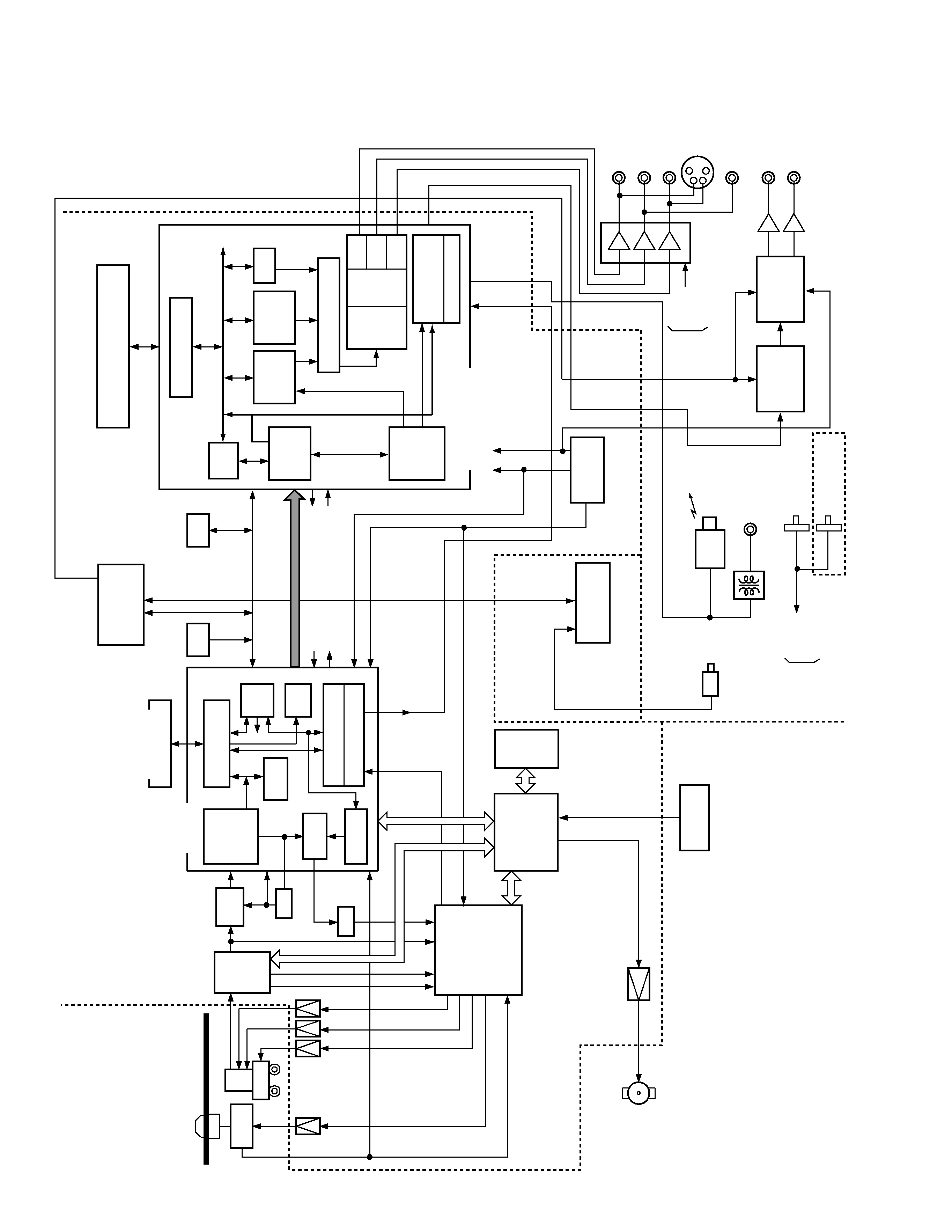
1. CIRCUIT DESCRIPTION
1.1 BLOCK DIAGRAM
3
DV-515
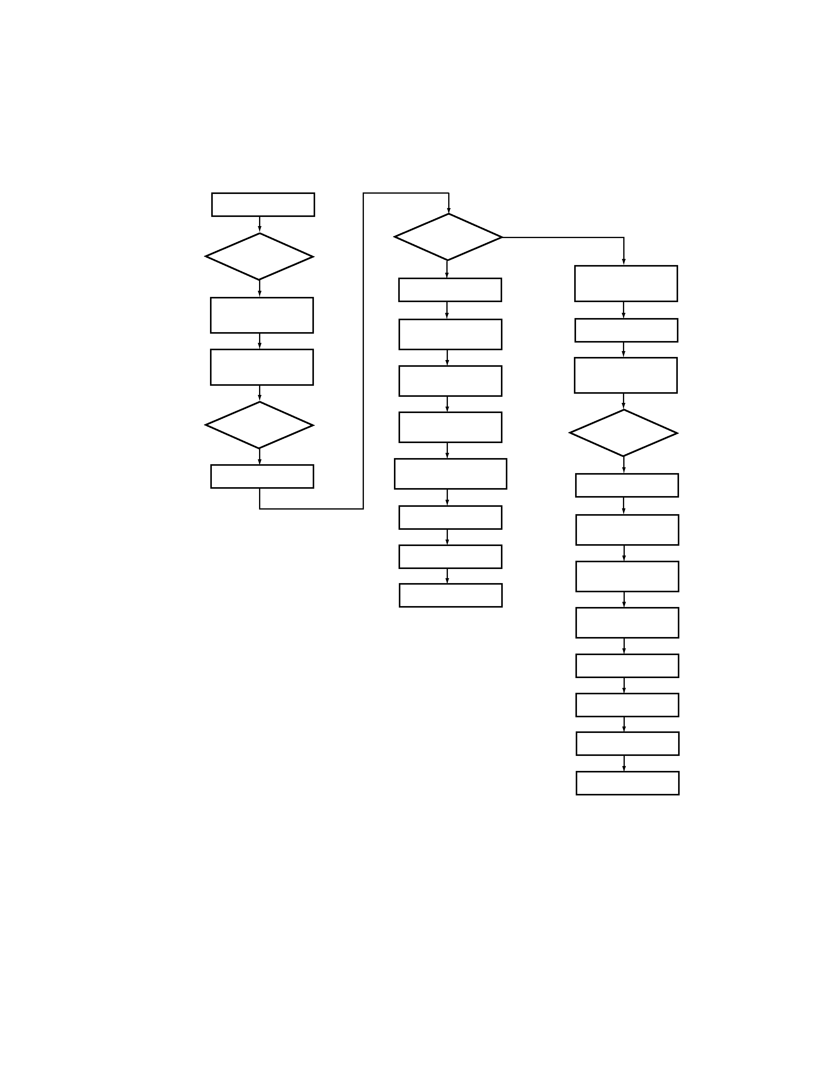
1.2 EXPLANATION OF EACH MOVEMENT
1.2.1 Sequence Up to Playback
SPDL ACCEL
Yes
780nm LD ON
780nm LD OFF
650nm LD ON
SWEEP
UP
DOWN
SWEEP
DOWN
UP
ATB ON
780nm LD ON
Layer Det.
Lead-in Search
PLAY
AFB Adj
TOC Read
Lead-in Search
PLAY
MIRR Modulation
Measurement
SPDL BRAKE
650nm LD OFF
T Servo ON
SLDR Servo ON
F Gain Adj.
T Gain Adj.
ATB ON
MIRR Modulation
Measurement
T Servo ON
SLDR Servo ON
F Gain Adj.
T Gain Adj.
AFB Adj.
(Auto Focus Balance)
Disc Exist ?
DVD
CD
Disc
Discrimination
Yes
Focus Lock
Yes
Focus Lock
4
DV-515
3
30
33
42
47
3
13
14
54 58 57
11
12
15 16 17 18 32
OEIC
PICKUP
FOCUS IN with 780nm LD
(Actually it is only at CD.)
FOCUS IN with 650nm LD
FDO
LDON
FE
UP
IC101
RFIC
LA9701M
IC201
DIGITAL
SERVO IC
LC78651W
IC501
MECH.
CONTROL
PE5012A
IC352
DRIVER
· FOCUS SERVO
· FOCUS LOCK TIMING
PH
LD1 ON
LD2 ON
RF
B1
B3
B2
B4
LD1
MD1
FOCUS
COIL
FE
OEIC GAIN
ADDRESS
&
BUS
SGC
FDO
LD2
MD2
57
19 20
42
UP
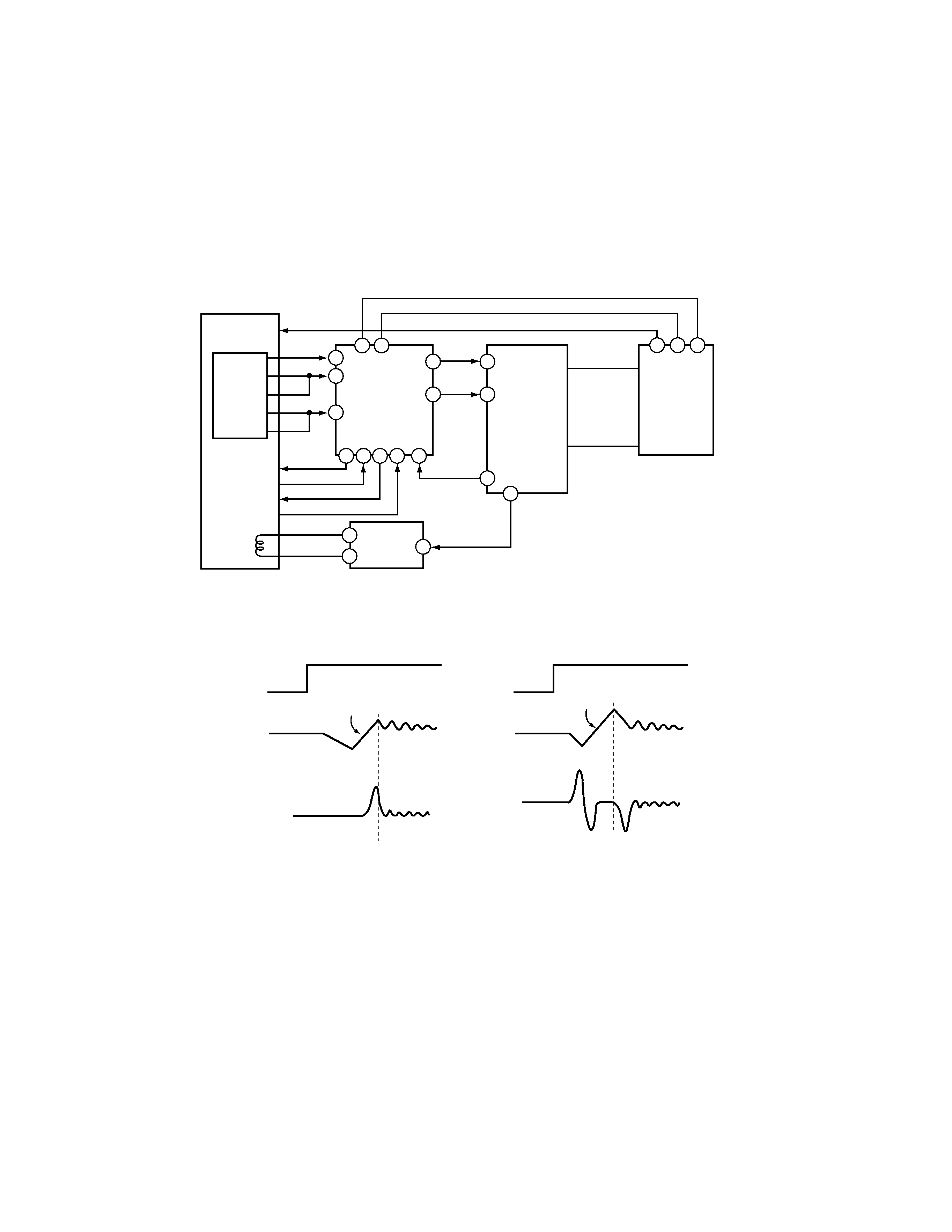
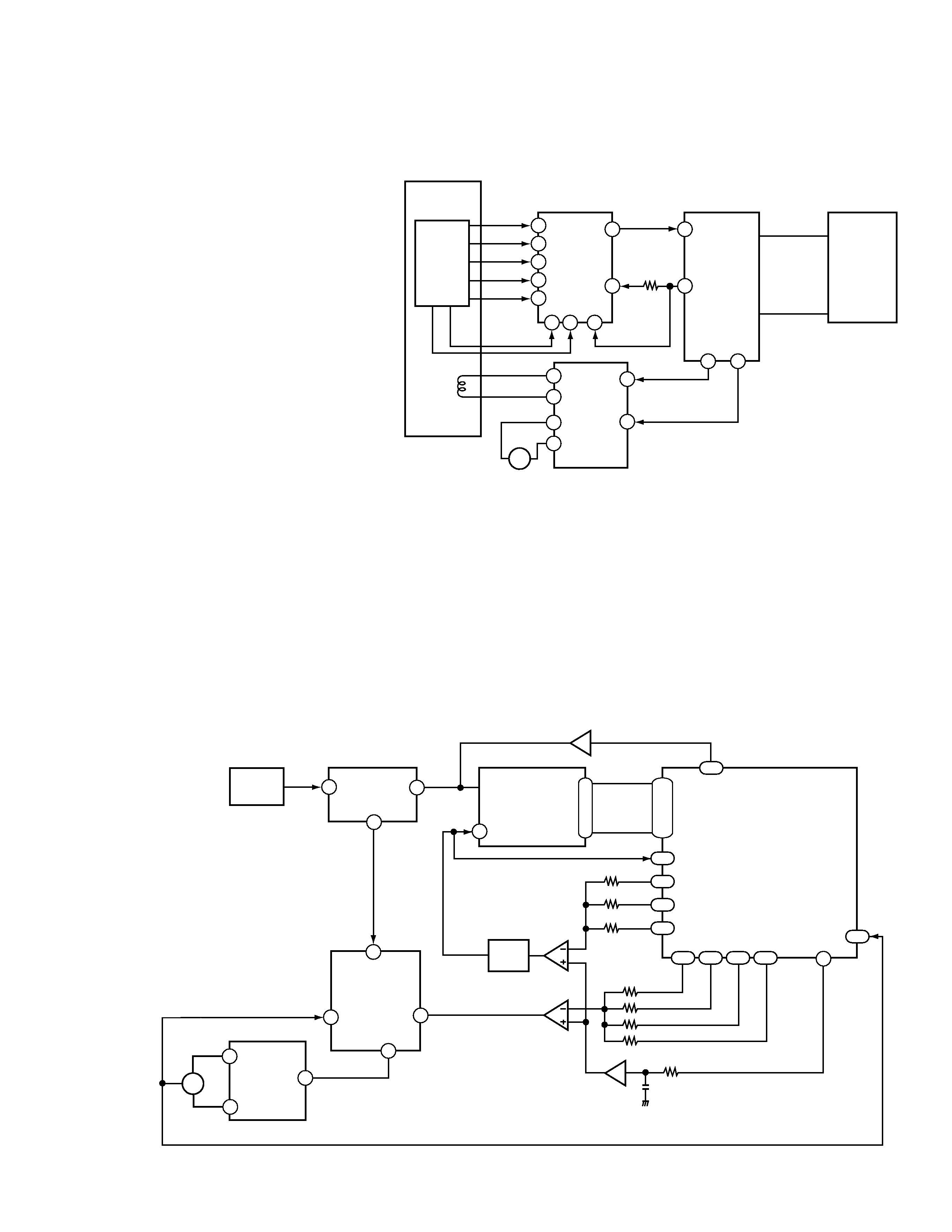
1.2.2 Focus Servo
FE generated in the RF IC is sent to the Digital servo IC.
Both DVD and CD, the servo is turned on during the transition
from "Upmost" to "Down" of the first-order sine wave with 650
nm LD ON (LD 1 ON = H). For a CD, it turns on during the transition
from "Down" to "Up" of the first-order sine wave with 780 nm LD
ON (LD 2 ON = H).
The kick-brake pulses, such as those for FOCUS jump, are also
output from pin 47 (FDO) of IC201.
5
DV-515
5
32
44
48
6
11
12
15
16
45
6
7
8
9
OEIC
PICKUP
IC101
RFIC
LA9701M
IC201
DIGITAL
SERVO IC
LC78651W
IC501
MECH.
CONTROL
PE5012A
IC151
DRIVER
SLDR
· TRACKING / SLIDER SERVO
TE
TE RF
B1
B2
B3
B4
TRKG
COIL
TBAL
ADDRESS
&
BUS
TDO
26
SLDO
M
35
39
13 14
30
CP
A
C
3
12
39
55
46
25
95
OEIC
IC101
RFIC
LA9701M
IC301
A/D
ADC1175CIJMX
IC701
LSI II
PD4833A
IC201
DIGITAL
SERVO
LC78651W
IC251
DRV
BA6195FP
· SPDL SERVO
RFO
RF
CLK
(27M)
8 bit
ATC
APC
AFC
ASC
V165
DUTY50
FG
VPWM
PPWM
RPWM
FPWM
29
54
46
RF
IC302
(1/2)
IC261
(2/2)
IC261
(1/2)
FG
SPDL +
SPDL -
SPDL
SPDO
(Base)
3
|
10
200
|
207
179
176
178
180
177
161 163 166 168
159
VCO
12
13
M
1.2.3 Tracking / Slider Servo
ATB: For phase differential TE (use for DVD),
the tracking balance compensation is
achieved by outputting the offset from
the TBAL output at pin 44 of the digital
servo IC, and by biasing the charge pump
resistor for phase-difference error of
RFIC.
For 3-beam TE (use for CD), the tracking
balance compensation is achieved by
adjusting the gain balance of A and C in
RFIC with the voltage of RFIC-pin 30.
The difference is detected by processing
TE at pin 32 of IC 201 with an internal
digital equalizer.
TDO: In addition to the servo output, the low-
band components, such as the kick-brake
for jump, are added for TDO output.
SLDO: The low-band components of TE are
processed by the internal digital
equalizer, and deadband is added for
SLDO output. The offset voltage for
pickup movement is also included in the
SLDO output.
1.2.4 SPINDLE SERVO
For a CD, the RF signal output from pin 46 of the RF IC is converted
to binary in IC201. By comparing the binary value with the reference
CLK (clock), the SPDL ERR signal is output from pin 46.
For a DVD, the SPDL ERR signal is generated from the PWM signal
output from LSI-
. Upon receiving this signal via pin 29, IC201
also outputs it from pin 46, switching from the CD SPDL ERR
signal.