ORDER NO.
PIONEER CORPORATION 4-1, Meguro 1-chome, Meguro-ku, Tokyo 153-8654, Japan
PIONEER ELECTRONICS (USA) INC. P.O. Box 1760, Long Beach, CA 90801-1760, U.S.A.
PIONEER EUROPE NV Haven 1087, Keetberglaan 1, 9120 Melsele, Belgium
PIONEER ELECTRONICS ASIACENTRE PTE. LTD. 253 Alexandra Road, #04-01, Singapore 159936
PIONEER CORPORATION 2002
DEH-P9400MP/EW
CRT2848
MULTI-CD/DAB CONTROL DSP HIGH POWER CD/MP3/WMA PLAYER WITH RDS TUNER
DEH-P9400MP
EW
This service manual should be used together with the following manual(s):
Model No.
Order No.
Mech.Module
Remarks
CX-3007
CRT2820
S9MP3
CD Mech. Module:Circuit Description,Mech. Description,Disassembly
For details, refer to "Important symbols for good services".
K-ZZS.FEB.2002.printed in Japan
DEH-P9400MP/EW
A
B
C
D
12
34
12
3
4
2
SAFETY INFORMATION
This service manual is intended for qualified service technicians; it is not meant for the casual do-it-yourselfer.
Qualified technicians have the necessary test equipment and tools, and have been trained to properly and safely repai
complex products such as those covered by this manual.
Improperly performed repairs can adversely affect the safety and reliability of the product and may void the warranty
If you are not qualified to perform the repair of this product properly and safely, you should not risk trying to do s
and refer the repair to a qualified service technician.
1. Safety Precautions for those who Service this Unit.
· When checking or adjusting the emitting power of the laser diode exercise caution in order to get safe, reliable
results.
Caution:
1. During repair or tests, minimum distance of 13cm from the focus lens must be kept.
2. During repair or tests, do not view laser beam for 10 seconds or longer.
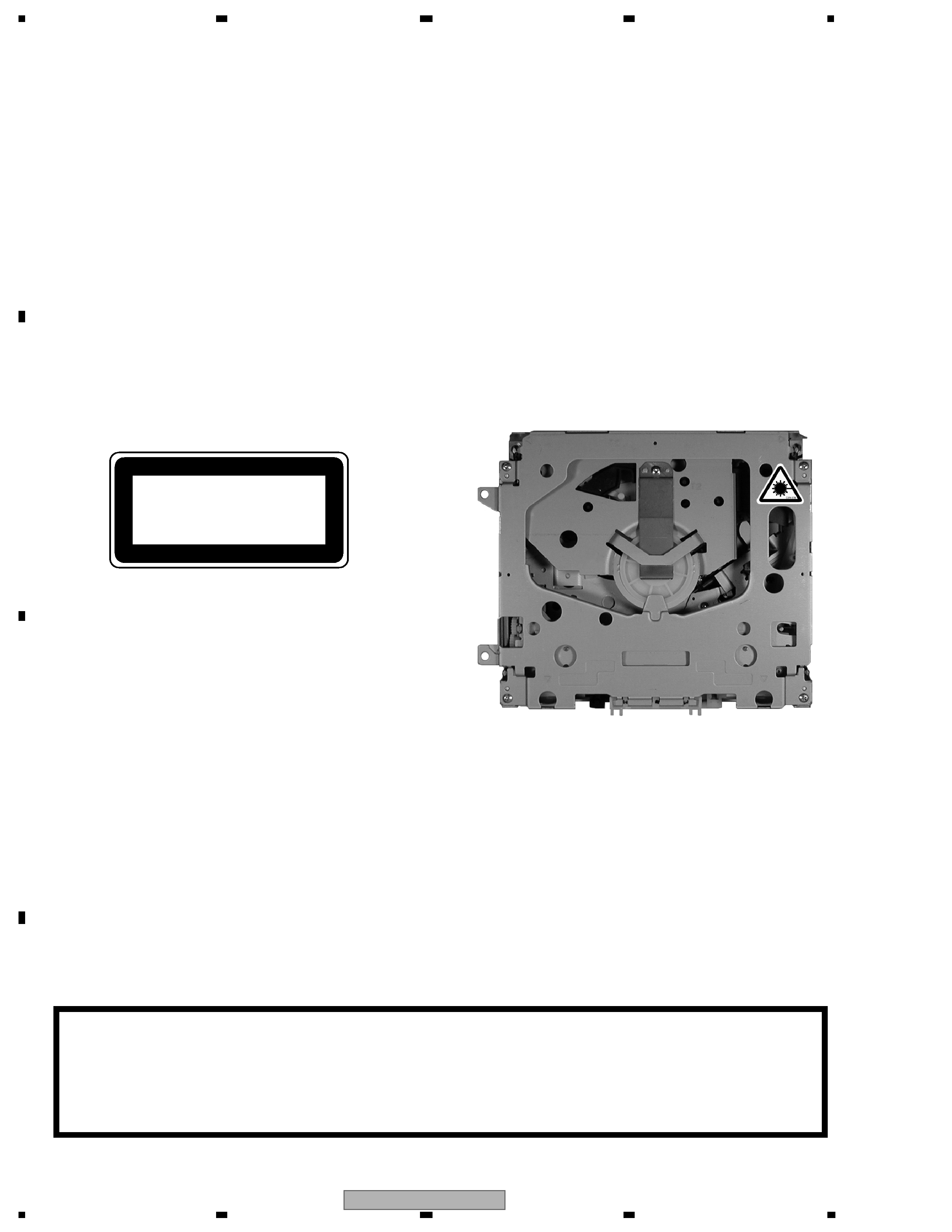
2. A "CLASS 1 LASER PRODUCT" label is affixed to the
bottom of the player.
3. The triangular label is attached to the mechanism
unit frame.
CLASS 1
LASER PRODUCT
4. Specifications of Laser Diode
Specifications of laser radiation fields to which human access is possible during service.
Wavelength
=
800 nanometers
CAUTION
Danger of explosion if battery is incorrectly replaced.
Replaced only with the same or equivalent type recommended by the manufacture.
Discord used batteries according to the manufacture's instructions.
DEH-P9400MP/EW
A
B
C
D
56
7
8
56
7
8
3
[ Important symbols for good services ]
In this manual, the symbols shown-below indicate that adjustments, settings or cleaning should be made securely.
When you find the procedures bearing any of the symbols, be sure to fulfill them:
2. Adjustments
To keep the original performances of the product, optimum adjustments or specification confirmation is indispensable.
In accordance with the procedures or instructions described in this manual, adjustments should be performed.
3. Cleaning
For optical pickups, tape-deck heads, lenses and mirrors used in projection monitors, and other parts requiring cleaning,
proper cleaning should be performed to restore their performances.
5. Lubricants, glues, and replacement parts
Appropriately applying grease or glue can maintain the product performances. But improper lubrication or applying
glue may lead to failures or troubles in the product. By following the instructions in this manual, be sure to apply the
prescribed grease or glue to proper portions by the appropriate amount.For replacement parts or tools, the prescribed
ones should be used.
4. Shipping mode and shipping screws
To protect the product from damages or failures that may be caused during transit, the shipping mode should be set or
the shipping screws should be installed before shipping out in accordance with this manual, if necessary.
1. Product safety
You should conform to the regulations governing the product (safety, radio and noise, and other regulations), and
should keep the safety during servicing by following the safety instructions described in this manual.

DEH-P9400MP/EW
A
B
C
D
12
34
12
3
4
4
CONTENTS
SAFETY INFORMATION . . . . . . . . . . . . . . . . . . . . . . . . . . . . . . . . . . . . . 2
1. SPECIFICATIONS . . . . . . . . . . . . . . . . . . . . . . . . . . . . . . . . . . . . . . . 5
2. EXPLODED VIEWS AND PARTS LIST . . . . . . . . . . . . . . . . . . . . . . . . . . . . 6
2.1 PACKING . . . . . . . . . . . . . . . . . . . . . . . . . . . . . . . . . . . . . . . . . 6
2.2 EXTERIOR(1) . . . . . . . . . . . . . . . . . . . . . . . . . . . . . . . . . . . . . . . 8
2.3 EXTERIOR(2) . . . . . . . . . . . . . . . . . . . . . . . . . . . . . . . . . . . . . . .10
2.4 CD MECHANISM MODULE . . . . . . . . . . . . . . . . . . . . . . . . . . . . . . . .12
3. BLOCK DIAGRAM AND SCHEMATIC DIAGRAM . . . . . . . . . . . . . . . . . . . . . . .14
3.1 BLOCK DIAGRAM . . . . . . . . . . . . . . . . . . . . . . . . . . . . . . . . . . . . .14
3.2 OVERALL CONNECTION DIAGRAM(GUIDE PAGE) . . . . . . . . . . . . . . . . . . .16
3.3 DSP UNIT . . . . . . . . . . . . . . . . . . . . . . . . . . . . . . . . . . . . . . . . .22
3.4 KEYBOARD UNIT . . . . . . . . . . . . . . . . . . . . . . . . . . . . . . . . . . . . .24
3.5 CD MECHANISM MODULE(GUIDE PAGE) . . . . . . . . . . . . . . . . . . . . . . . .26
4. PCB CONNECTION DIAGRAM . . . . . . . . . . . . . . . . . . . . . . . . . . . . . . . .34
4.1 TUNER AMP UNIT. . . . . . . . . . . . . . . . . . . . . . . . . . . . . . . . . . . . .34
4.2 DSP UNIT . . . . . . . . . . . . . . . . . . . . . . . . . . . . . . . . . . . . . . . . .38
4.3 KEYBOARD UNIT . . . . . . . . . . . . . . . . . . . . . . . . . . . . . . . . . . . . .40
4.4 CD CORE UNIT(S9MP3) . . . . . . . . . . . . . . . . . . . . . . . . . . . . . . . . .42
4.5 EQ PCB , SWITCH PCB . . . . . . . . . . . . . . . . . . . . . . . . . . . . . . . . . .44
5. ELECTRICAL PARTS LIST . . . . . . . . . . . . . . . . . . . . . . . . . . . . . . . . . .45
6. ADJUSTMENT . . . . . . . . . . . . . . . . . . . . . . . . . . . . . . . . . . . . . . . . .55
6.1 CD ADJUSTMENT. . . . . . . . . . . . . . . . . . . . . . . . . . . . . . . . . . . . .55
6.2 CHECKING THE GRATING AFTER CHANGING THE PICKUP UNIT . . . . . . . . . .57
6.3 TEST MODE . . . . . . . . . . . . . . . . . . . . . . . . . . . . . . . . . . . . . . . .59
6.4 DISPLAY TEST MODE . . . . . . . . . . . . . . . . . . . . . . . . . . . . . . . . . .60
7. GENERAL INFORMATION . . . . . . . . . . . . . . . . . . . . . . . . . . . . . . . . . . .62
7.1 DIAGNOSIS . . . . . . . . . . . . . . . . . . . . . . . . . . . . . . . . . . . . . . . .62
7.1.1 DISASSEMBLY . . . . . . . . . . . . . . . . . . . . . . . . . . . . . . . . . . . . .62
7.1.2 CONNECTOR FUNCTION DESCRIPTION . . . . . . . . . . . . . . . . . . . . . . .66
7.2 IC . . . . . . . . . . . . . . . . . . . . . . . . . . . . . . . . . . . . . . . . . . . . .67
7.3 OPERATIONAL FLOW CHART . . . . . . . . . . . . . . . . . . . . . . . . . . . . . .87
7.4 CLEANING. . . . . . . . . . . . . . . . . . . . . . . . . . . . . . . . . . . . . . . . .88
8. OPERATIONS . . . . . . . . . . . . . . . . . . . . . . . . . . . . . . . . . . . . . . . . .89
- CD Player Service Precautions
2. For pickup unit(CXX1550) handling, please refer
to"Disassembly"(see page 62)
During replacement, handling precautions shall be
taken to prevent an electrostatic discharge(protection
by a jumper-solder).
3. During disassembly, be sure to turn the power off
since an internal IC might be destroyed when a con-
nector is plugged or unplugged.
4. Please checking the grating after changing the ser-
vice pickup unit(see page 57).
1. Before shipping out the repaired product, confirm the
position of the DSP MODE switch; the switch should
be set to the side that the customer previously select-
ed.
If the switch is set to the STD side on the product
where the NW side was selected, the speakers con-
nected may be damaged.

DEH-P9400MP/EW
A
B
C
D
56
7
8
56
7
8
5
1. SPECIFICATIONS
General
Power source 14.4 V DC (10.8 15.1 V allowable)
Grounding system .......................... Negative type
Max. current consumption .......................... 10.0 A
Backup current .............................. Less than 6 mA
Dimensions
(mounting size) ...... 178 (W)
× 50 (H) × 157 (D)
mm
(front face) ........ 188 (W)
× 58 (H) × 24 (D) mm
Weight ............................................................ 1.7 kg
Audio/DSP
Maximum power output .......................... 50 W
× 4
Continuous power output ........................ 27 W
× 4
(DIN45324, +B = 14.4 V)
Load impedance ................ 4
(4 8 allowable)
Preout maximum output
level/output impedance ................ 4.0 V/100
Loudness contour .... +10 dB (100 Hz), +6.5 dB (10
kHz)
(volume: 30 dB)
Equalizer (13-Band Graphic Equalizer)
Frequency ........ 50/80/125/200/315/500/800 Hz
1.25/2/3.15/5/8/12.5 kHz
Equalization range ....................
±12 dB (2 dB)
Auto Equalizer (Just for standard mode)
(Front & Rear & Subwoofer 13-Band Graphic)
Frequency ........ 50/80/125/200/315/500/800 Hz
1.25/2/3.15/5/8/12.5 kHz
Equalization range .......... +6 -- 12 dB (2 dB)
Network (Standard mode)
HPF (Front/Rear)
Frequency ................ 50/63/80/100/125 Hz
Slope ...................................... 12 dB/oct.
Subwoofer
Frequency ................ 50/63/80/100/125 Hz
Slope ........................................ 18 dB/oct.
Gain ...................... 24 dB -- +6 dB (1 dB)
Phase .............................. Normal/Reverse
Network (3-way network mode)
HIGH HPF
Frequency
........1.6/2/2.5/3.15/4/5/6.3/8/10/12.5/16 kHz
Slope .................................. 6/12 dB/oct.
Gain .............. 24 dB -- 0 dB/Mute (1 dB)
Phase .............................. Normal/Reverse
MID HPF/LPF
Frequency (LPF)
........1.6/2/2.5/3.15/4/5/6.3/8/10/12.5/16 kHz
Frequency (HPF)
..........31.5/40/50/63/80/100/125/160/200 Hz
Slope (LPF) .......... 0 (Pass)/6/12 dB/oct.
Slope (HPF) .. 0 (Pass)/6/12/18 dB/oct.
Gain .............. 24 dB -- 0 dB/Mute (1 dB)
Phase .............................. Normal/Reverse
LOW LPF
Frequency
..........31.5/40/50/63/80/100/125/160/200 Hz
Slope ............................ 6/12/18 dB/oct.
Gain ............ 24 dB -- +6 dB/Mute (1 dB)
Phase .............................. Normal/Reverse
CD player
System ...................... Compact disc audio system
Usable discs ...................................... Compact disc
Signal format ........ Sampling frequency: 44.1 kHz
Number of quantization bits: 16; linear
Frequency characteristics .... 5 20,000 Hz (
±1 dB)
Signal-to-noise ratio ........ 94 dB (1 kHz) (IEC-A n
work)
Dynamic range .................................. 92 dB (1 kHz)
Number of channels ................................ 2 (stereo)
MP3 decoding format ........ MPEG-1 and 2 AUD
LAYER-3
WMA decoding format ...................... Ver. 7 and 8
FM tuner
Frequency range ............................ 87.5 108 MHz
Usable sensitivity ............................................ 9 dBf
(0.8 mV/75
, mono, S/N: 30 dB)
50 dB quieting sensitivity ............................ 15 dBf
(1.5 mV/75
, mono)
Signal-to-noise ratio .......... 70 dB (IEC-A network)
Distortion .............. 0.3% (at 65 dBf, 1 kHz, stereo)
Frequency response .......... 30 15,000 Hz (
±3 dB)
Stereo separation ............ 40 dB (at 65 dBf, 1 kHz)
MW tuner
Frequency range .............. 531 1,602 kHz (9 kHz)
Usable sensitivity .................... 18 mV (S/N: 20 dB)
Selectivity ........................................ 50 dB (
±9 kHz)
LW tuner
Frequency range .............................. 153 281 kHz
Usable sensitivity .................... 30 mV (S/N: 20 dB)
Selectivity ........................................ 50 dB (
±9 kHz)
Note:
· Specifications and design are subject to modifica-
tion without notice for the sake of improvements.