ORDER NO.
PIONEER CORPORATION 4-1, Meguro 1-chome, Meguro-ku, Tokyo 153-8654, Japan
PIONEER ELECTRONICS (USA) INC. P.O. Box 1760, Long Beach, CA 90801-1760, U.S.A.
PIONEER EUROPE NV Haven 1087, Keetberglaan 1, 9120 Melsele, Belgium
PIONEER ELECTRONICS ASIACENTRE PTE. LTD. 253 Alexandra Road, #04-01, Singapore 159936
PIONEER CORPORATION 2002
ARP3145
T ZZV DEC. 2002 Printed in Japan
DBR-S400F
DBR-S400I
DBR-S400NL
DIGITAL SATELLITE RECEIVER
This service manual should be used together with the following manual(s):
Remarks
Order No.
TS7/NYXK/FR
ARP3129
Model
Type
Model
Power Requirement
Remarks
DBR-S400F
DBR-S400I DBR-S400NL
NYXK/FR
AC230V
NYXK/IT
AC230V
NYXK/NL
AC230V
THIS MANUAL IS APPLICABLE TO THE FOLLOWING MODEL(S) AND TYPE(S).
1. CONTRAST OF MISCHELLANEOUS PARTS ....... 2
2. SCHEMATIC DIAGRAM .......................................... 4
3. PCB CONNECTION DIAGRAM ............................ 25
CONTENTS
DBR-S400F, DBR-S400I, DBR-S400NL
2
1
23
4
12
3
4
C
D
F
A
B
E
PCB ASSEMBLIES
P9-1
MAIN ASSY
BWE1129
BWE1139
BWE1140
BWE1141
IC3001(16M FLASH Memory)*
BGC1079-A-RD* BGC1086-A-RD* BGC1087-A-RD* BGC1088-A-RD* *Set service part
RETAIL BLOCK
B9E1135
B9E1135
B9E1135
B9E1135
P9-2
FRONT ASSY
BWX1216
BWX1222
BWX1222
BWX1222
PACKING SECTION
P7-1
Packing Case
BHD1507
BHD1544
BHD1545
BHD1546
Pulp Mold F (
Design change from Side Pad L)
BHX1028
Not used
Not used
Not used
Pulp Mold R (
Design change from Side Pad R)
BHX1029
Not used
Not used
Not used
P7-2
Side Pad L
Not used
BHA1146
BHA1146
BHA1146
P7-3
Side Pad R
Not used
BHA1147
BHA1147
BHA1147
P7-5
Remote Control Unit
BXD1010
BXD1059
BXD1060
BXD1061
P7-6
NSP
Battery 2P (R03/AAA)
VEM1018
Not used
Not used
Not used
P7-6
NSP
Battery 2P (R6P/AA)
Not used
VEM1017
VEM1017
VEM1017
P7-7
Instruction Manual
BRC1054
BRC1062
BRC1063
BRC1064
(French)
(French)
(Italian)
(Dutch)
P7-9
NSP
CE Declaration Sheet
BRM1057
Not used
Not used
Not used
NSP
White Card
Not used
BPK1019
Not used
Not used
NSP
Warranty Card
Not used
BRY1052
BRY1053
BRY1054
NSP
Brochure (Dutch)
Not used
Not used
Not used
BRY1025
NSP
Registration Form
Not used
Not used
Not used
BRY1026
NSP
Seca Smart Card Kit
Not used
Not used
Not used
BPK1020
P7-13
Modem Cable
BDH1040
BDH1040
BDH1041
BDH1037
P7-14
NSP
Modem Adapter
Not used
Not used
Not used
BKP1140
EXTERIOR SECTION
P9-7
19P FFC
BDD1057
BDD1059
BDD1059
BDD1059
P9-9
Front Panel Assy
BWX1217
Not used
Not used
Not used
P9-9
Front Panel Assy
Not used
BMB1183
BMB1184
BMB1185
Display Panel
Not used
BAK1196
BAK1197
BAK1198
Pioneer Name Plate
Not used
VAM1129
VAM1129
VAM1129
P9-11
Rear Panel Assy
BWX1221
BWX1234
BWX1235
BWX1236
P9-12
Bonnet Case
BNE1136
BNE1138
BNE1138
BNE1138
P9-16
NSP
Name Label
BAL1449
BAL1477
BAL1478
BAL1479
P9-30
Serial No. Label
BAX1145
BAX1145
BAX1189
BAX1258
Screw (for SR Pin Jack)
Not used
BBZ30P080FZK BBZ30P080FZK BBZ30P080FZK
No.1
CONTRAST TABLE
DBR-S400F/NYXK/FR, DBR-S400I/NYXK/IT, DBR-S400NL/NYXK/NL and TS7/NYXK/FR are constructed the
same except for the following:
Remarks
Part No.
TS7
/NYXK/FR
Ref.
No.
Mark
Symbol and Description
DBR-S400F
/NYXK/FR
DBR-S400I
/NYXK/IT
DBR-S400NL
/NYXK/NL
1. CONTRAST OF MISCELLANEOUS PARTS
jp
f
y
For the applying amount of lubricants or glue, follow the instructions in this manual.
(In the case of no amount instructions, apply as you think it appropriate.)
Parts marked by "NSP" are generally unavailable because they are not in our Master Spare Parts List.
The
mark found on some component parts indicates the importance of the safety factor of the part.
Therefore, when replacing, be sure to use parts of identical designation.
Screws adjacent to
mark on product are used for disassembly.
Reference Nos. indicate the pages and Nos. in the service manual for the base model.
NOTES:
·When ordering resistors, first convert resistance values into code form as shown in the following examples.
Ex.1 When there are 2 effective digits (any digit apart from 0), such as 560 ohm and 47k ohm (tolerance is shown by J=5%,
and K=10%).
560
56
× 101
561 ........................................................ RD1/4PU 5 6 1 J
47k
47
× 103
473 ........................................................ RD1/4PU 4 7 3 J
0.5
R50 ..................................................................................... RN2H R 5 0 K
1
1R0 ..................................................................................... RS1P 1 R 0 K
Ex.2 When there are 3 effective digits (such as in high precision metal film resistors).
5.62k
562
× 101
5621 ...................................................... RN1/4PC 5 6 2 1 F
Notes:
÷ The numbers in the remarks column correspond to the numbers on "EXTERIOR".
÷ For ASSEMBLIES, refer to "CONTRAST OF PCB ASSEMBLIES" , "2. SCHEMATIC DIAGRAM" and "3. PCB CONNECTION
DIAGRAM".
3
1
23
4
1
2
3
4
C
D
F
A
B
E
DBR-S400F, DBR-S400I, DBR-S400NL
SUB CPU BLOCK
R7018
RS1/16S102J
Not used
Not used
Not used
R7043
RS/16S103J
Not used
Not used
Not used
R7044
Not used
RS1/16S103J
RS1/16S103J
RS1/16S103J
RETAIL BLOCK
IC8001 (SRS IC)
Not used
NJM2179M
NJM2179M
NJM2179M
Q8501, Q8502
Not used
UMG1N
UMG1N
UMG1N
Q8503
Not used
2SA1576A
2SA1576A
2SA1576A
D8501-D8503
Not used
1SS355
1SS355
1SS355
C8008, C8009
Not used
CEHAT4R7M50 CEHAT4R7M50 CEHAT4R7M50
C8001
Not used
CKSRYB472K50 CKSRYB472K50 CKSRYB472K50
C8004, C8005
Not used
CKSRYF104Z16 CKSRYF104Z16 CKSRYF104Z16
C8002, C8003
Not used
CKSRYB474K10 CKSRYB474K10 CKSRYB474K10
C8006, C8007, C8501
Not used
CKSRYB105K6R3 CKSRYB105K6R3 CKSRYB105K6R3
R8001, R8012
Not used
RS1/16S102J
RS1/16S102J
RS1/16S102J
R8007
Not used
RS1/16S152J
RS1/16S152J
RS1/16S152J
R8005
Not used
RS1/16S392J
RS1/16S392J
RS1/16S392J
R8002
Not used
RS1/16S432J
RS1/16S432J
RS1/16S432J
R8504
Not used
RS1/16S472J
RS1/16S472J
RS1/16S472J
R8009, R8010
Not used
RS1/16S512J
RS1/16S512J
RS1/16S512J
R8011
Not used
RS1/16S912J
RS1/16S912J
RS1/16S912J
R8501, R8502, R8506
Not used
RS1/16S103J
RS1/16S103J
RS1/16S103J
R8503
Not used
RS1/16S273J
RS1/16S273J
RS1/16S273J
R8006
Not used
RS1/16S333J
RS1/16S333J
RS1/16S333J
R8004
Not used
RS1/16S473J
RS1/16S473J
RS1/16S473J
R8008
Not used
RS1/16S623J
RS1/16S623J
RS1/16S623J
R8003
Not used
RS1/16S114J
RS1/16S114J
RS1/16S114J
R8505
Not used
RS1/16S224J
RS1/16S224J
RS1/16S224J
CN8501 (SR Pin Jack)
Not used
VKN1034
VKN1034
VKN1034
Serial No. Label
BAX1145
BAX1145
BAX1189
BAX1258
MAIN ASSY
BWE1139, BWE1140, BWE1141 and BWE1129 are constructed the same except for the following:
CONTRAST OF PCB ASSEMBLIES
A
Mark
Symbol and Description
Part No.
BWE1129
BWE1139
BWE1140
BWE1141
Remarks
FRONT ASSY
B
SEMICONDUCTORS
D8409
BEL1046
D8410
SLR-343VC
SWITCHES AND RELAYS
S8404-S8407
ASG1034
Mark No.
Description
Part No.
Mark No.
Description
Part No.
RESISTORS
R8401 (27k
/1/2W)
BCN1056
R8402 (10k
/1/4W)
BCN1069
OTHERS
M8401
Remote Sensor Unit
BXX1034
CN8401
19P FFC Connector
9607S-19F
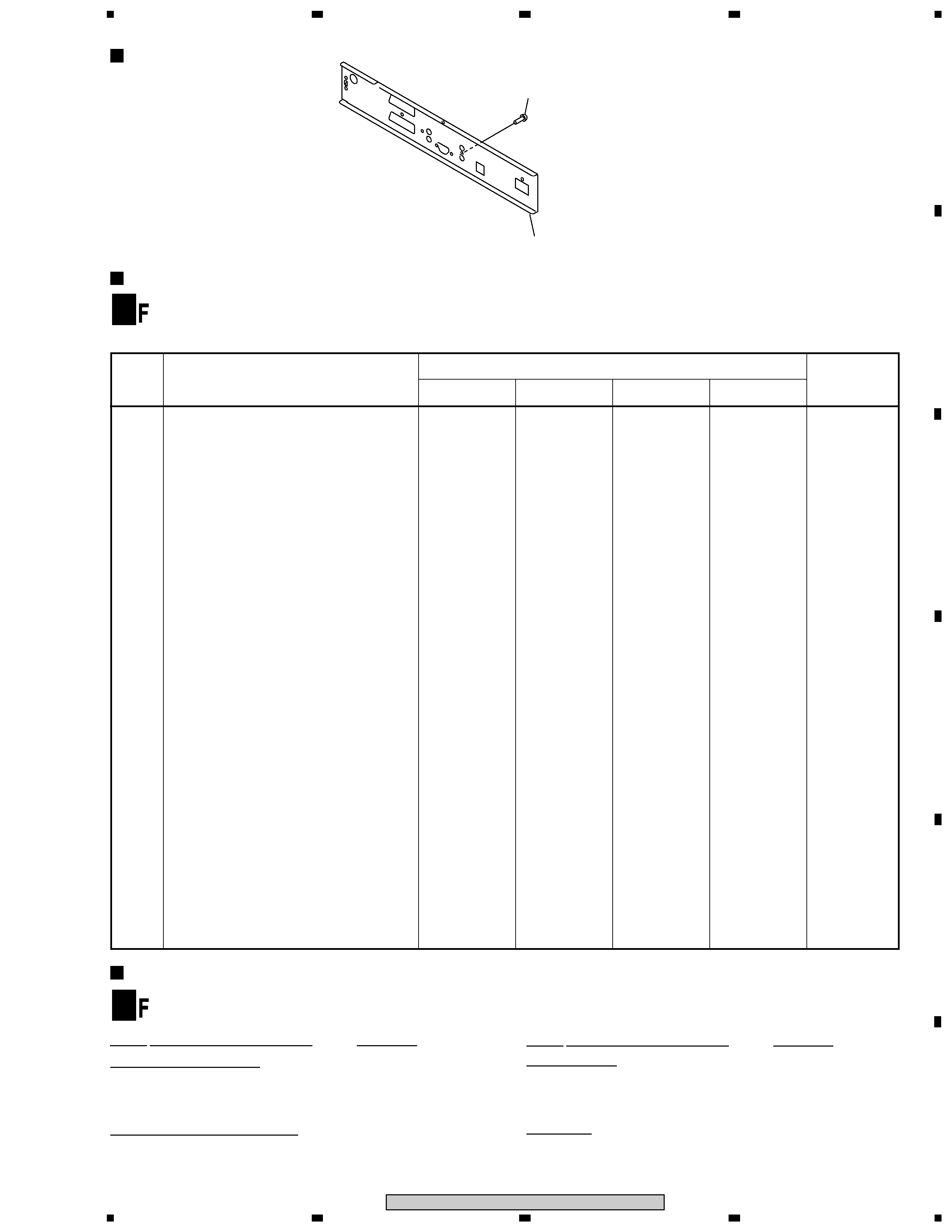
EXTERIOR
No.1(Screw for
SR Pin Jack)
Rear Panel
PCB PARTS LIST
4
1
23
4
12
3
4
C
D
F
A
B
E
DBR-S400F, DBR-S400I, DBR-S400NL
MAIN ASSY
(BWE1139 : DBR-S400F)
(BWE1140 : DBR-S400I)
(BWE1141 : DBR-S400NL)
CARD ASSY
(BWE1132)
C
A
A F
1/9F-
(
A 9/9F)
BXF1167-
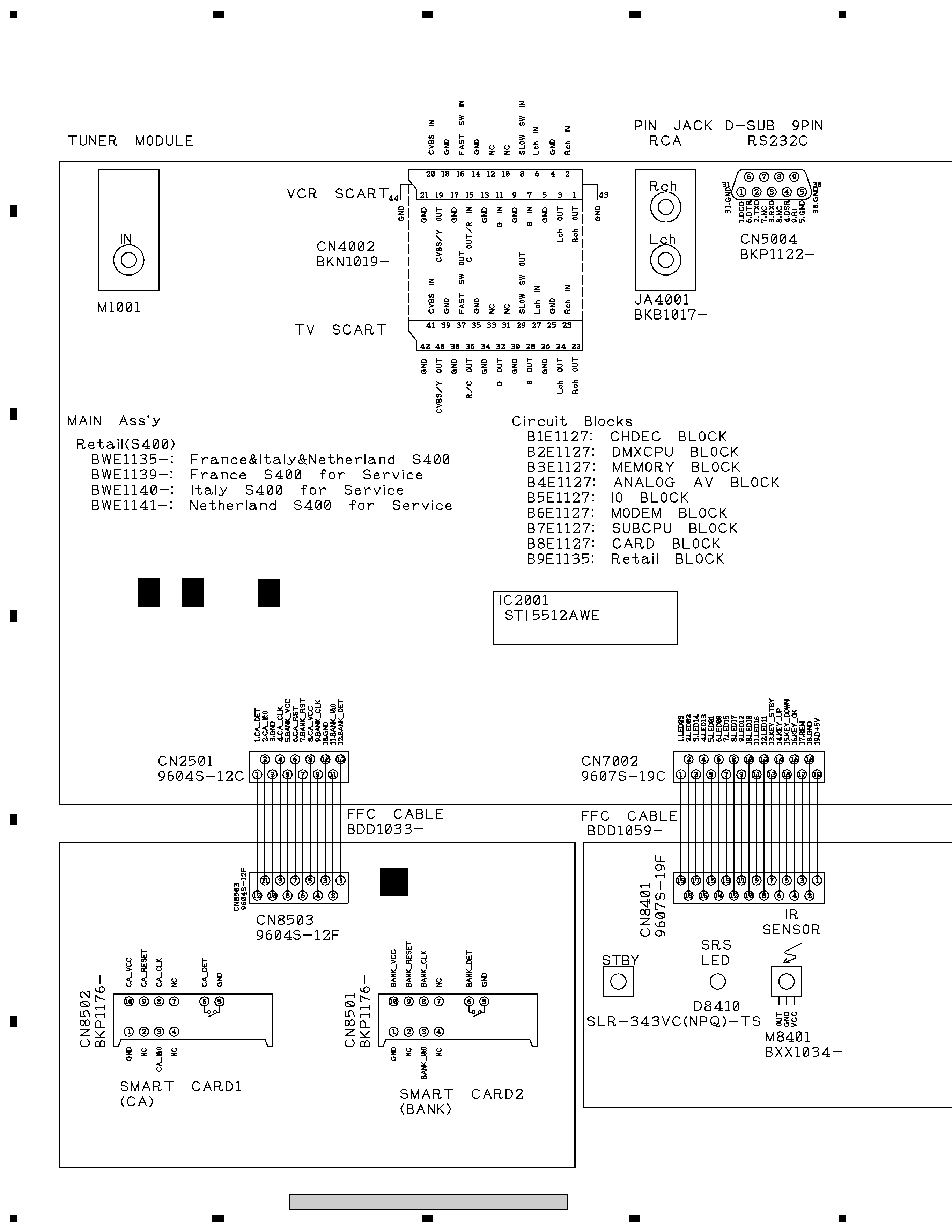
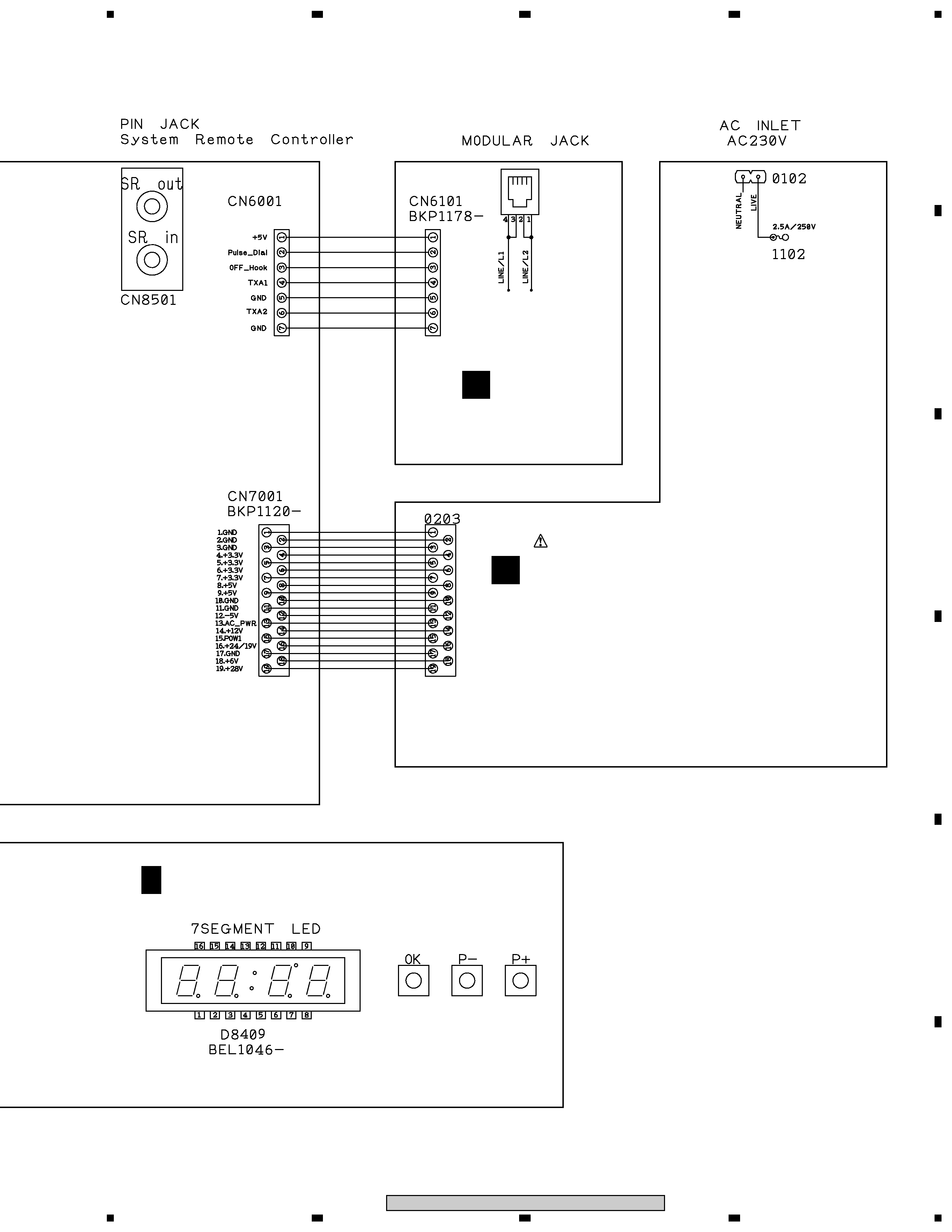
2. BLOCK DIAGRAM AND SCHEMATIC DIAGRAM
2.1 OVERALL WIRING DIAGRAM
5
5
67
8
5
6
7
8
C
D
F
A
B
E
DBR-S400F, DBR-S400I, DBR-S400NL
FRONT ASSY (BWX1222)
POWER ASSY
(BXF1166)
E
BF
MODEM ASSY
(BWX1215)
D
BKM1085-
VKN1034-
CN6102
BKP1137-
Note : When ordering service parts, be sure to refer to "EXPLODED VIEWS and PARTS LIST" or "PCB PARTS LIST"