
Model
Service Manual
DVD/CD Mechanism Unit
XDV-P9/UC,EW,ES/RC,ES/RD
CRT2511
CXK7010
PIONEER CORPORATION
4-1, Meguro 1-Chome, Meguro-ku, Tokyo 153-8654, Japan
PIONEER ELECTRONICS SERVICE INC.
P.O.Box 1760, Long Beach, CA 90801-1760 U.S.A.
PIONEER EUROPE N.V.
Haven 1087 Keetberglaan 1, 9120 Melsele, Belgium
PIONEER ELECTRONICS ASIACENTRE PTE.LTD. 253 Alexandra Road, #04-01, Singapore 159936
C PIONEER CORPORATION 2000
K-ZZS. MAY 2000 Printed in Japan
ORDER NO.
CRT2533
DVD/CD MECHANISM UNIT
CX-692
Service
Manual
- This service manual describes the operation of the DVD/CD mechanism incorporated in models listed
in the table below.
- When performing repairs use this manual together with the specific manual for model under repair.
CONTENTS
1. CIRCUIT DESCRIPTIONS ...........................................2
2. DISASSEMBLY .........................................................20
3. MECHANISM DESCRIPTIONS.................................24
2
CX-692
Q104
PICKUP UNIT
IC103 TA1254AF
45 LDO1
MDI1
44
GND
7
VCC
8
VPS
IC101
3
4
2
1
IM
CP
OUT
PICKUP UNIT
Fig. 1
Fig. 2
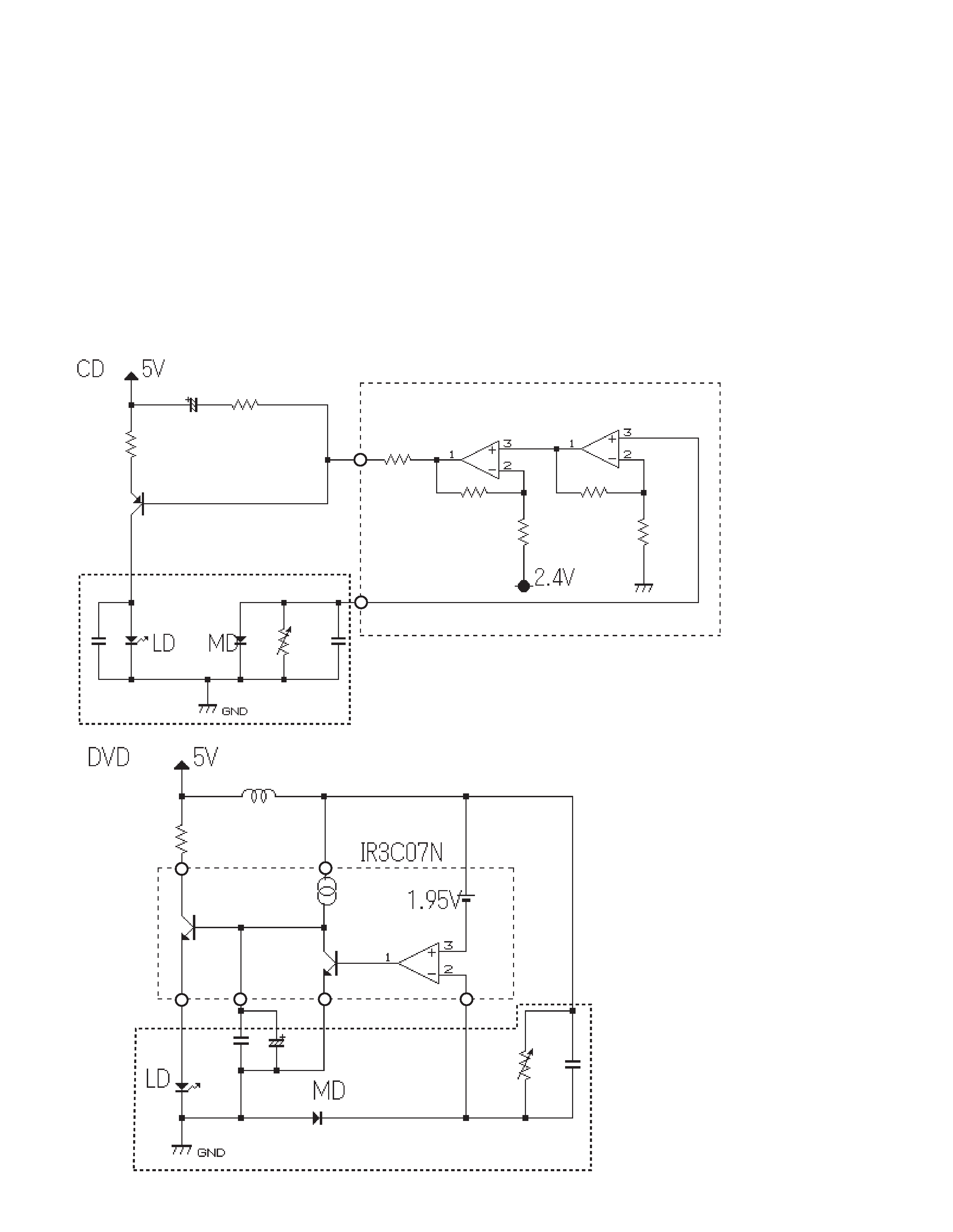
1. Circuit Description
1.1 APC circuit
- APC (Automatic Power Control) circuit
[Fig. 1 CD and Fig. 2 DVD]
Since the optical output of laser beam diodes carries a
large negatived temperature characteristic, necessary
optical power cannot be acquired when driven at a
lower current level.
The APC circuit is a circuit to
control the current levels so that the output of the
monitor diode may become constant.
By measuring
the voltage occurring between the LD and the drive
transistor, the LD current can be found out and such
current value should be within ±20% of the value
indicated on the pickup unit flexible P.C. board when
handling the CD and should be 50mA or less when
handling the DVD.
CX-692
3
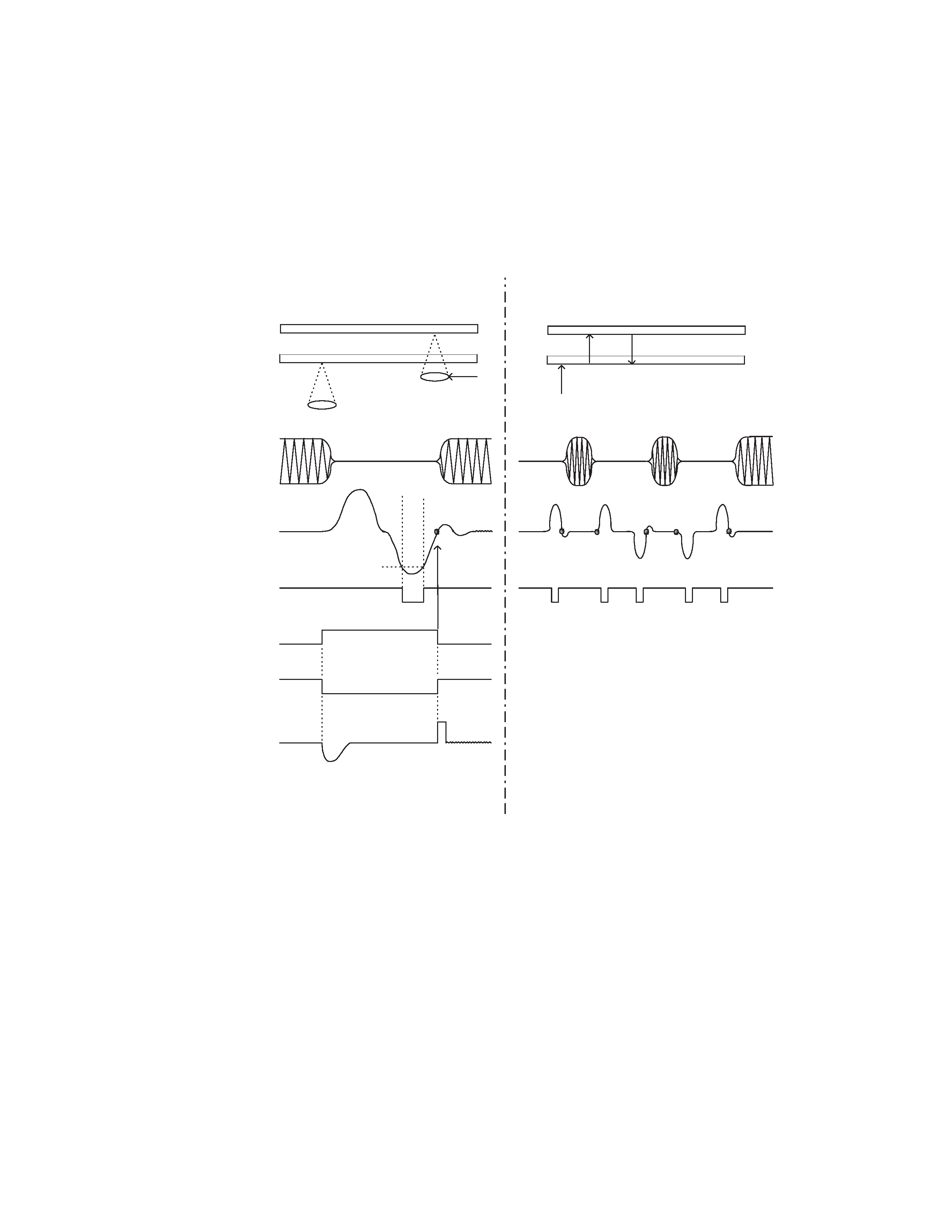
1.2 FOCUS-JUMPING CIRCUIT
Focus-jumping function is a function conforming to
single side 2-layer discs or double-side 2 layer discs.
Fig. 3 below shows the basic movement sequence.
Viewing through the objective lens, the layer on this
side is called Layer 0 (L0) and the layer on the far side is
called the Layer 1 (L1).
Objective lens
RF
FE
Focus
standby level
Focus ON
Vref
GND
Vref
A(Fig.4)
TEST00
B(Fig.4)
IO0
L0
=L1
L1
=L0
L0
L1
L0
L1
L0
(Layer1) L1
(Layer0) L0
L1
L0
A
B
C
D
E
A
B
C
D
E
Fig. 3
4
CX-692
Described below are the explanations of the basic
movements.
When the focus-jumping command is issued from the
mechanism controller (IC501:PD5511A), the input to the
focus equalizer is changed over from the AD converter
output (FOO) to the DC hold filter output and DC
holding is effected.
Simultaneously, the focus search drive signals are
output through the TESIO0 pin and the TESIO1 pin. By
the circuit shown in Fig. 4, these signals are made to
apply drive signals to the focusing servo loop which
work to drive the focusing actuator to complete the
layer jump.
FOO
19
FOJ
Q401
Q402
IC402
NJM2904M
IC401
67
43
18
19
IC304
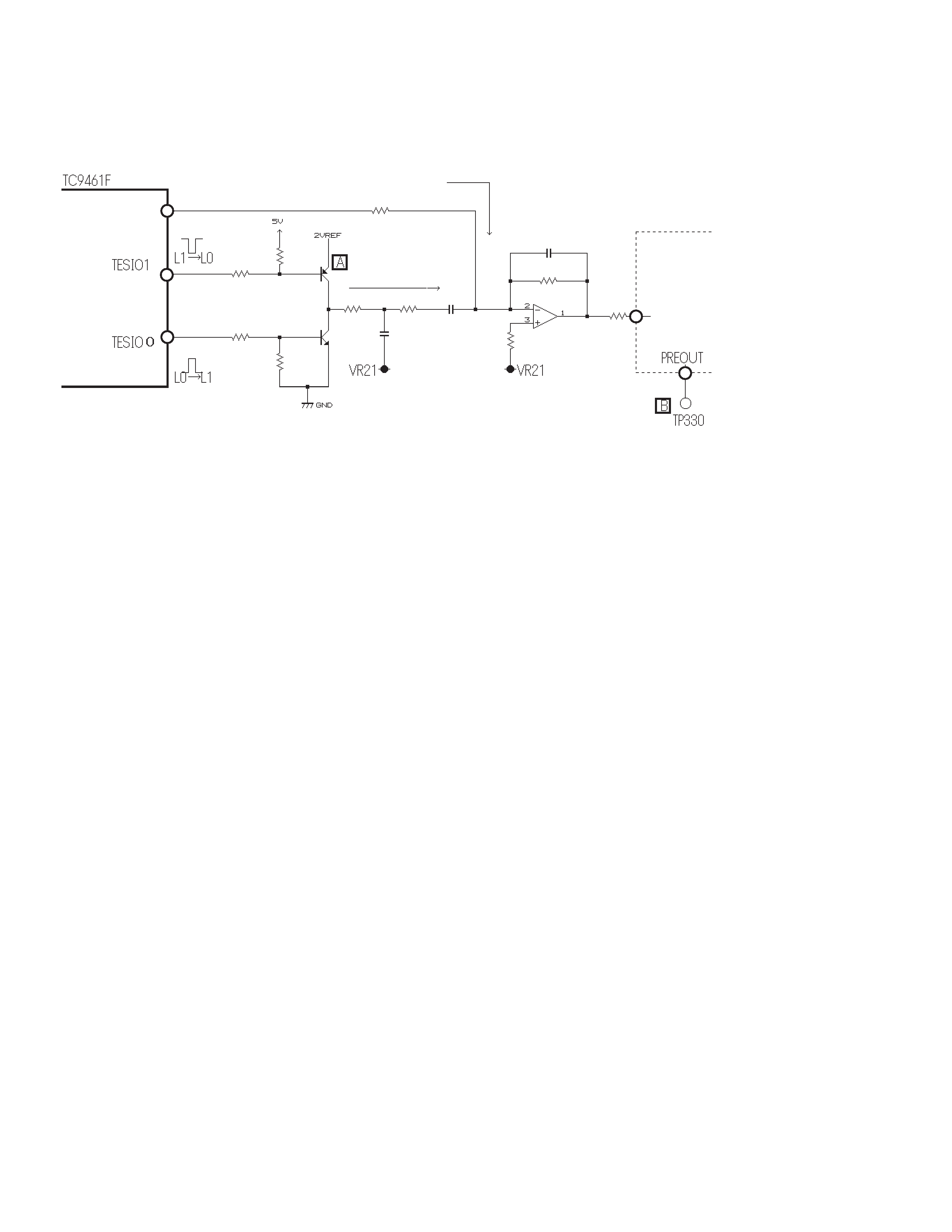
BA6797FM
Focus-jumping circuit
Normal state
While focus-jumping
is in progress
Fig. 4
CX-692
5
Under normal CD settings: F-GAIN = 0.5dB, FE-GAIN = 3.0dB
Under normal DVD settings: F-GAIN = -4.5dB, FE-GAIN = 6.0dB
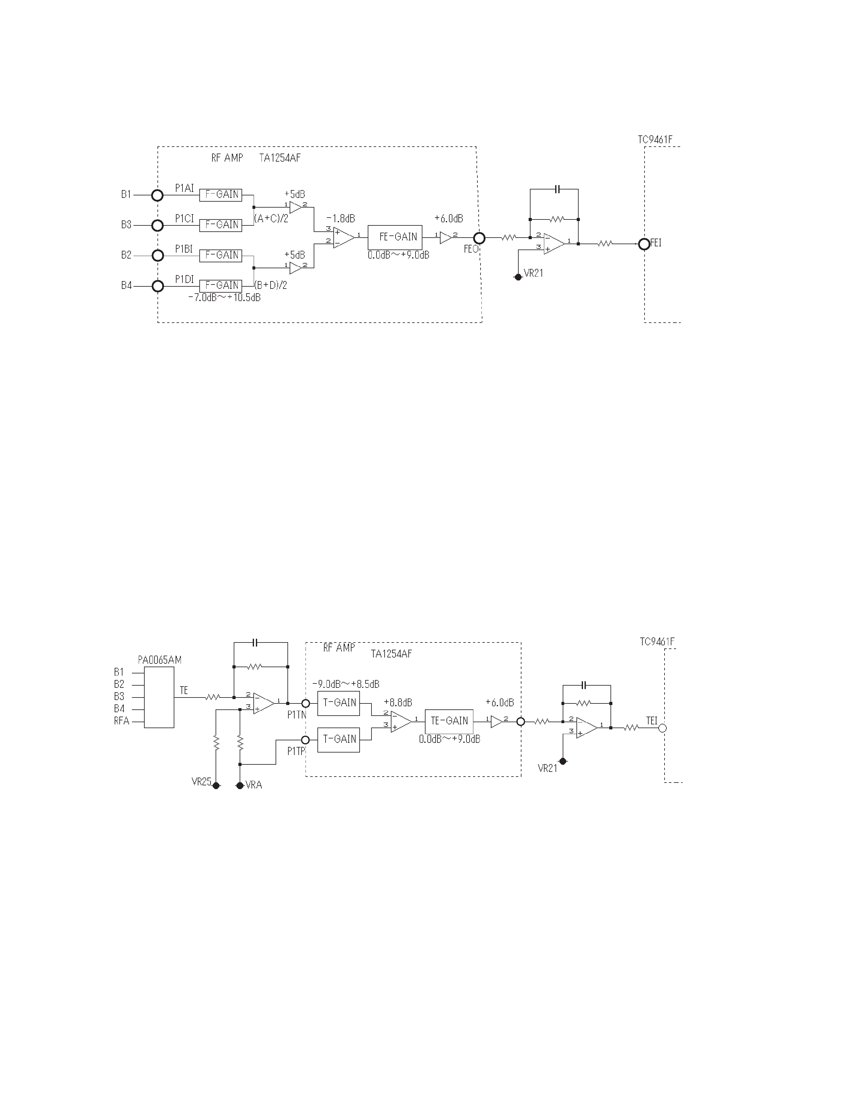
1.4 TRACKING ERROR SIGNAL
GENERATING CIRCUIT
Tracking error signals are being formed by amplifying the RFA
being generated through the B1 - B4 of the pickup unit output
and the RF amplifier (IC103:TA1254AF) by the
TC7WU04FU(IC106,109) and by inputting these signals to the
time difference IC (IC107:PA0065AM). The error signals being
output from the time difference IC are amplified through the OP
amplifier(IC108) and the RF amplifier(IC103) before being input
to the servo DSP (IC401:TC9461F pin41).
Under normal CD settings: T-GAIN = -9.0dB, TE-GAIN = 0.0dB
Under normal DVD settings: T-GAIN = -9.0dB, TE-GAIN = 6.0dB
IC103
55
53
54
52
21
IC105
NJM3404AM
IC401
38
IC107
2
8
4
10
6
19
IC108
NJM3404AM
IC103
46
47
20
TEO
IC108
NJM3404AM
41
IC401
Fig. 5
Fig. 6
1.3 FOCUS ERROR AMPLIFIER