
ORDER NO.
PIONEER CORPORATION 4-1, Meguro 1-chome, Meguro-ku, Tokyo 153-8654, Japan
PIONEER ELECTRONICS (USA) INC. P.O. Box 1760, Long Beach, CA 90801-1760, U.S.A.
PIONEER EUROPE NV Haven 1087, Keetberglaan 1, 9120 Melsele, Belgium
PIONEER ELECTRONICS ASIACENTRE PTE. LTD. 253 Alexandra Road, #04-01, Singapore 159936
PIONEER CORPORATION 2004
CRT3257
DVD MECHANISM MODULE(MS-3V1)
CX-3078
This service manual describes the operation of the DVD mechanism modules
incorporated in the models listed below.
When performing repairs use this manual together with the specific manual for the
model under repair.
Model No.
Service Manual
DVD Mechanism Module
AVH-P6600DVD/UC
CRT3193
CXK6410
DVH-P5650/RC
CRT3264
CXK6414
K-ZZU. MAR. 2004 printed in Japan
CONTENTS
1. CIRCUIT DESCRIPTIONS . . . . . . . . . . . . . . . . . . . . . . . . . . . . . . . . 2
2. MECHANISM DESCRIPTIONS . . . . . . . . . . . . . . . . . . . . . . . . . . . 13
3. DISASSEMBLY . . . . . . . . . . . . . . . . . . . . . . . . . . . . . . . . . . . . . . . . 18
CX-3078
2
1234
123
4
C
D
F
A
B
E
+
+
+
+5V
+5V
MD
0.25V
0.5V
0.59V
0.18V
0.22V
CDLD0
CDLD1
CN1101
24
5
26
7
LPCO2
PU unit
LDONCD
LDPOWER
LDONDVD
LPC2
3.9
3.9 3.9 3.9
+
0.17V
0.25V
0.18V
+5V
DVDLD0
DVDLD1
LPCO1
LPC1
3.9
3.9 3.9 3.9
+
+
+
Reg.
78LD
CD
LD
DVD
LD
78MD
65LD
65MD
1 Front End Part (MN35103UB, MN35104UB:IC1501)
MN35103UB and MN35104UB are 1-chip LSI for DVD-Player. The connection of this LSI to the Driver IC,
SDRAM, Flash-ROM, Audio-DAC, etc. can configure the DVD-Player System.
This LSI contains Front End (SODC/FE) that performs RF signal /Servo /Decode processings, Back End
(AV decoder/BE) that performs the video decode processing such as MPEG1/MPEG2/JPEG and audio decode
processing such as DVD-Audio/AC-3/DTS/MP3, and the system controller (Siscon) for controlling the system.
Front End part realizes the arithmetic processing of optical head signal and RF signal processing,
the digital signal processing for DVD-ROM reproduction that conforms to DVD standards (16-8 Demodulation,
Error correction), the digital signal processing for CD-DA/CD-ROM (Error correction), AV decoder transmission,
servo control, spindle motor control and seek control.
Please take note that, since (FEP) and (SODC) with DVD mecha-module (MS3) of CX-3016 are integrated into
one chip at MN35103UB and MN35104UB, the waveforms of servo system on the front end which had
previously appeared at MS3, i.e., the waveforms of FE, TE and AS, cannot be seen anymore.
1.1 Analog Block (MN35103UB, MN35104UB:IC1501)
The analog block for IC1501 generates the servo signals including focus and tracking, processes addition of
RF signals, and controls the laser power of pickup.
The servo system contains focus operation amp, focus offset adjustment circuit, 3-beam tracking operation amp,
phase difference tracking detection circuit, tracking offset adjustment circuit, TE2 value-making circuit.
Also, RF signal processing system contains the functions of AGC and equalizer.
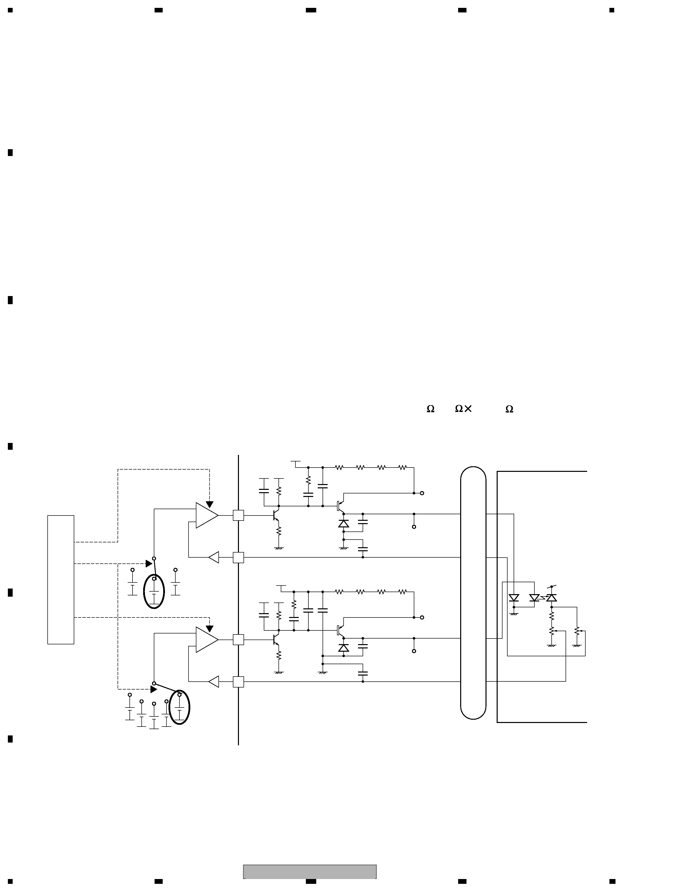
1.1.1 APC Circuit
The optical output for the laser diode (LD) has large minus temperature characteristics. Therefore, the constant
optical output cannot be obtained when LD is driven by the constant current. APC circuit controls the electric
current so as to provide constant output at the monitor diode (MD). MN35103UB and MN35104UB contain two
types of APC circuits, one for DVD and another for CD. The LD electric current for DVD (CD) can be obtained by
dividing the voltage measurements between DVDLD1 (CDLD1) and 5V by 15.6
(3.9
4=15.6 ). For DVD (CD),
the results are approx. 26mA (44mA).
1. CIRCUIT DESCRIPTIONS
CX-3078
3
5
678
56
7
8
C
D
F
A
B
E
+
+
OFFSET ADJ
1+(Pfbal/0x10000)
1+(Pfbal/0x10000)
1-(Pfbal/0x10000)
Analog block
Servo block
FE+
Pfepofs
+
+
OFFSET ADJ
FE-
Pfenofs
1+(Pfbal/0x10000)
1-(Pfbal/0x10000)
1+(Pfbal/0x10000)
1-(Pfbal/0x10000)
+
VIN6
15
92
+
VIN7
13
93
+
VIN8
11
94
+
VIN5
16
91
CN1101
B4
B3
B2
B1
Dfesv
FE
x1 or x4
+
+
OFFSET ADJ
Analog block
Servo block
TE+
Pfepofs
+
+
OFFSET ADJ
TE-
Pfenofs
+
VIN2
15
96
+
VIN3
13
97
+
VIN4
11
98
+
VIN1
16
95
CN1101
B4
B3
B2
B1
Dfesv
TE
x1 or x4
+
+
+
+
EQ
EQ
EQ
EQ
PC
PC
+
+
OFFSET DAC
Analog block
Servo block
TE+
Pfepofs
+
+
OFFSET DAC
TE-
G
G
Pfenofs
+
VIN9
VREFH
20k
VHALF
17
CN1101
A
Dfesv
TE
- 6dB 15dB(3dB STEP)
- 6dB 15dB(3dB STEP)
30kHz
30kHz
0dB/12dB
0dB/12dB
+
VIN10
VREFH
20k
VHALF
10
C
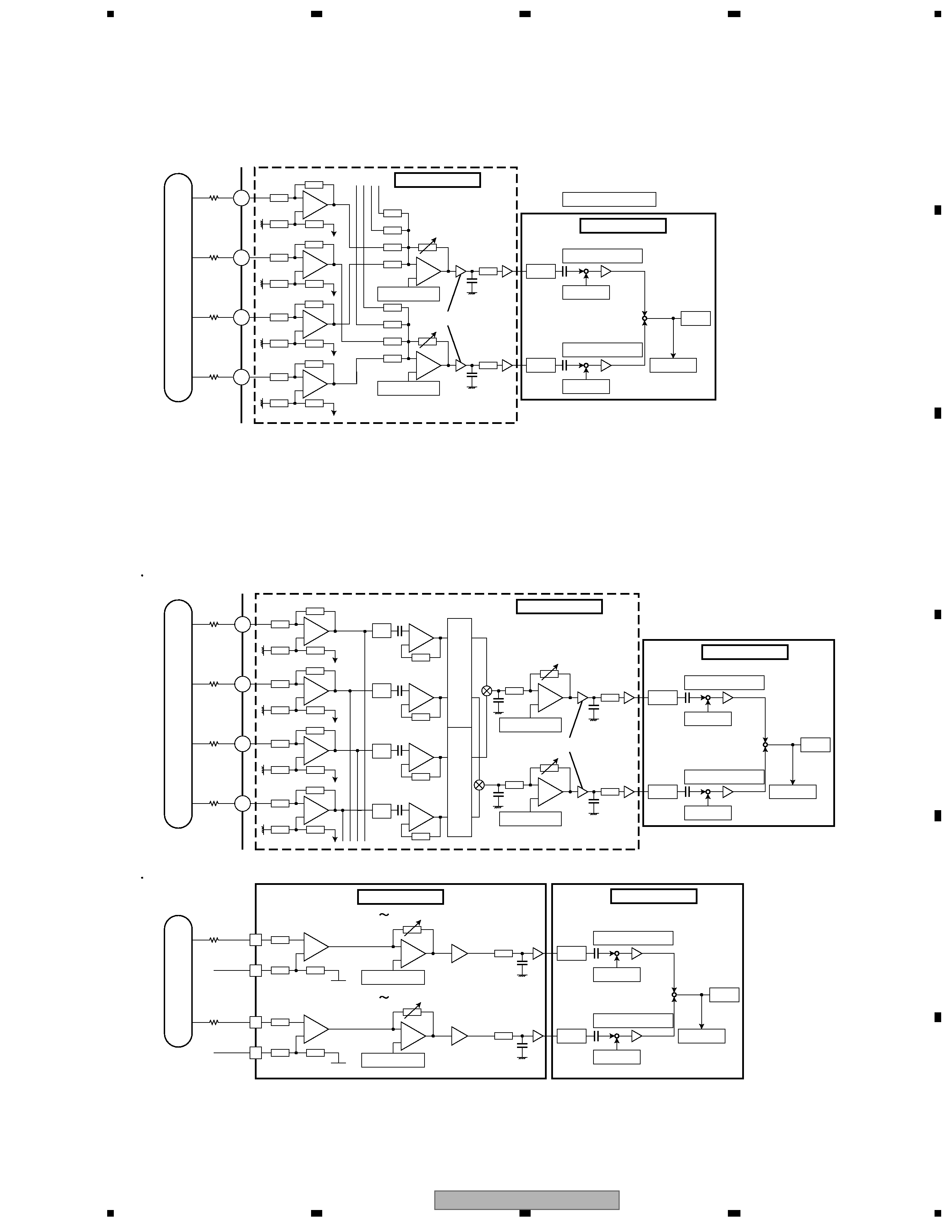
1.1.2 FE Generation Circuit
Focus Error (FE) Generation Circuit
Each of input signals from B1 to B4 which had been quartered by PU within the analog block is input to IC 1501
passing through the resistance and becomes a signal of FE+= - (B1+B3) and FE- = - (B2+B4) after adding a focus
offset adjustment value. Then, the signal is AD-converted within the servo block and adds an offset cancel value
to become FE, generating a signal of FE=(FE+)- (FE- ).
1.1.3 TE Generation Circuit
Trackings Error (TE) Generation Circuit
For DVD, TE is generated, with the application of a phase contrast method, from the phase difference of (B2+B4)
and (B1+B3). For CD, TE is generated, with the application of a 3-beam method, by sending the signal to the
variable amp set for the tracking offset adjustment via outer-attached resistance and then by AD-converting it to
make the formula of TE=A- C.
DVD (TE from phase difference)
CD (3-beam TE)
CX-3078
4
1234
123
4
C
D
F
A
B
E
1.2 Servo Block (MN35103UB, MN35104UB:IC1501)
Servo block performs focus, tracking, servo control for traverse, spindle motor control and seek control.
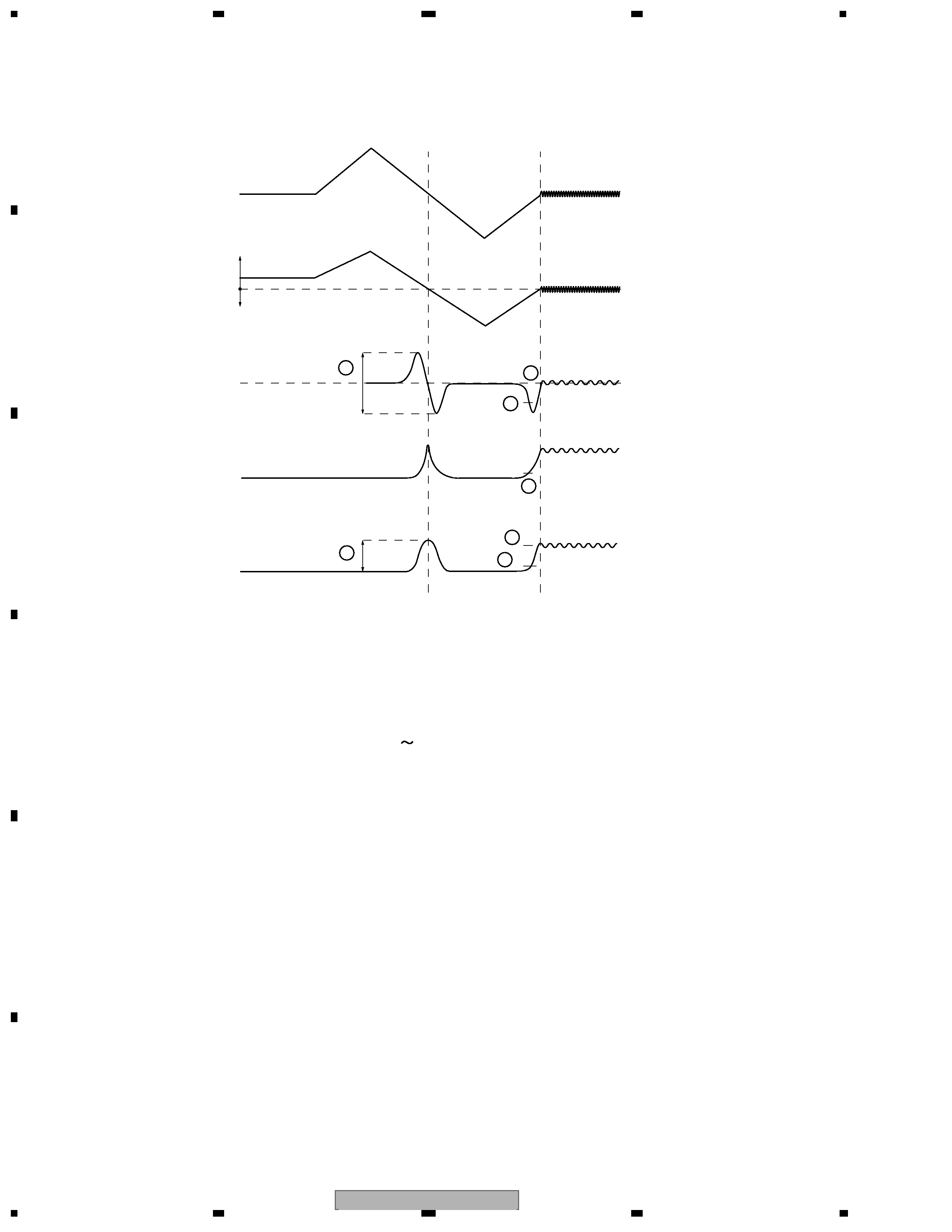
After issuing the focus close command, the following processes are taken for both DVD and CD.
1. Measure and optimize signal levels
First drive PU lens far from the disc and then drive closer to the disc. At the focal point met in the process of
this move, measure signal levels of FE, AS and RFENV respectively, and optimize their levels for FE and AS
(1 & 2 in the above figure).
2. Focus closing
Next, drive the lens far from the disc again to detect the closing levels of FE and AS.
Then activate focus loop filter for closing focus (3
6).
3. Check closing
Check the closing with signal levels of AS and RFENV (6 & 7).
Focus search in test mode can check the signal levels and focus drive voltages for FE, AS and RFEV.
1.2.1 Focus Close
1.2.2 Tracking Close
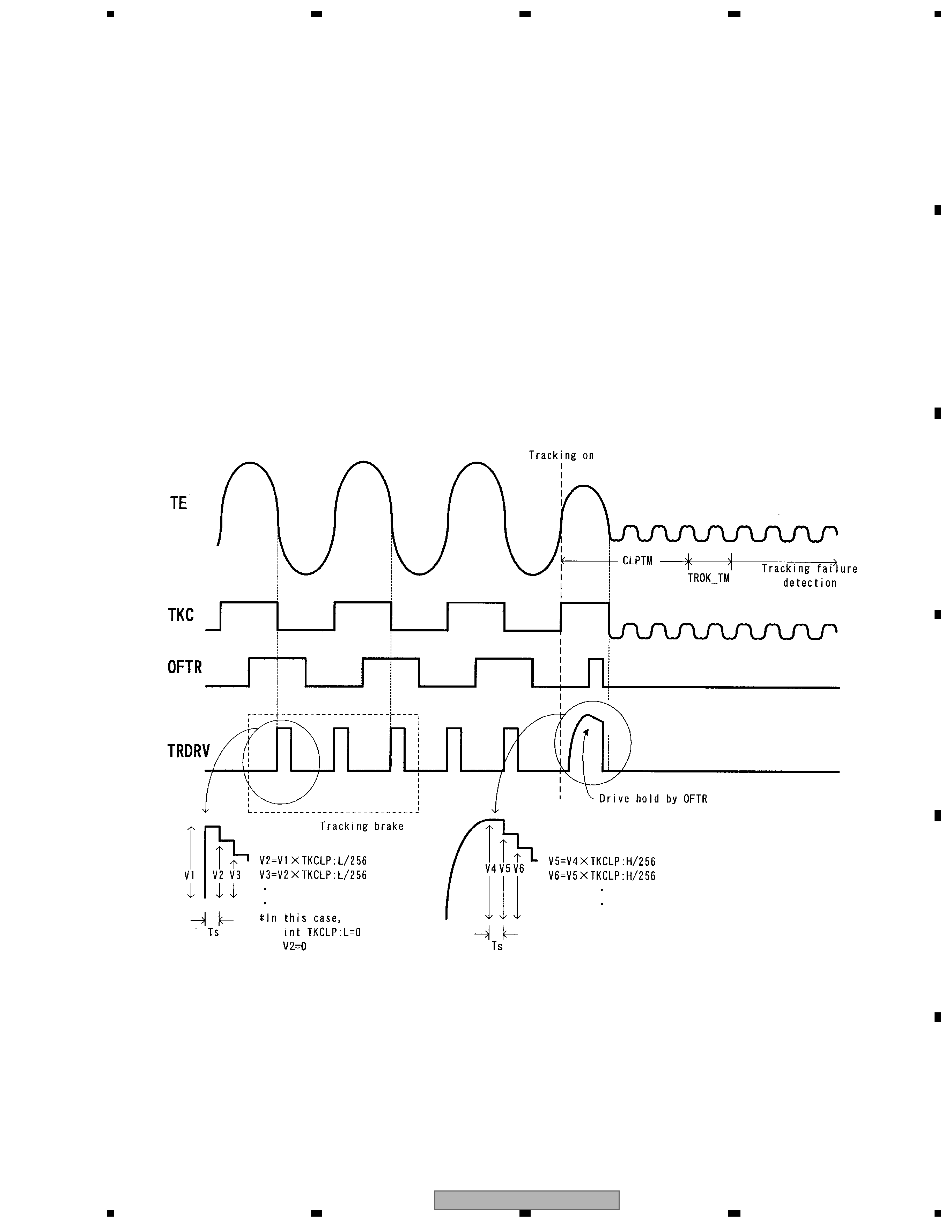
After issuing the tracking close command, the following processes are taken for both DVD and CD
1. Tracking brake
Measure one half cycle of the tracking cross and if the cycle is within the range of designation, output the brake
pals.
Output direction of brake pals is determined by the phase relations of OFTR and TKC (TE's binarization) signals.
After confirming that the swing of lens against disc is controlled, the brake stops and the closing begins. If the
closing condition is not met within 10msec. after outputting brake, the brake stops and the closing begins.
2. Tracking closing
Process the tracking drive hold with OFTR signal.
3. Check closing
Check whether or not the track jump does not exceed the designated number within the designated term.
Closing check will be time-out at 20msec. Retry using a command from the microcomputer.
3
6
7
4
5
1
2
Close to disc
Far from disc
Lens
VHALF
Focal point
FE
RFENV
AS
FODRV
CX-3078
5
5
678
56
7
8
C
D
F
A
B
E
1.2.3 Track Jump
The system selects from three types of methods; i.e. interval jump, multi jump and traverse seek,
according to the target number of moving tracks.
1. Interval Jump
The detailed seek is capable due to the execution of repetitive one-track jumps.
It is used when approaching to the target track or seek-operating to an adjacent track.
2. Multi Jump
It counts both edges of the track cross signal TKC and moves for designated number of track counts.
3. Traverse Seek
It controls the movement speed by measuring the time of the track cross signal TKC and manages the
vibration of pickup generated upon movement to the minimum.
Types of target number of moving jumps illustrating the jump switch setting for both DVD and CD
DVD
1-10 Interval Jump
11-100 Multi Jump
101-500 Combination of Multi Jump and Interval Jump
Over 501 Traverse Seek
The waveforms of track jumps are shown in the next page.
CD
1-10 Interval Jump
11-32 Multi Jump
33-500 Combination of Multi Jump and Interval Jump
Over 501 Traverse Seek