ORDER NO.
PIONEER CORPORATION 4-1, Meguro 1-chome, Meguro-ku, Tokyo 153-8654, Japan
PIONEER ELECTRONICS SERVICE, INC. P.O. Box 1760, Long Beach, CA 90801-1760, U.S.A.
PIONEER ELECTRONIC (EUROPE) N.V. Haven 1087, Keetberglaan 1, 9120 Melsele, Belgium
PIONEER ELECTRONICS ASIACENTRE PTE. LTD. 253 Alexandra Road, #04-01, Singapore 159936
PIONEER CORPORATION 1999
c
CT-W208R
RRV2186
1. SAFETY INFORMATION ...................................... 2
2. EXPLODED VIEWS AND PARTS LIST ................ 3
3. BLOCK DIAGRAM AND SCHEMATIC DIAGRAM .. 10
4. PCB CONNECTION DIAGRAM .......................... 18
5. PCB PARTS LIST ............................................... 24
6. ADJUSTMENT .................................................... 27
CONTENTS
7. GENERAL INFORMATION ................................ 31
7.1 DIAGNOSIS ................................................. 31
7.1.1 POWER ON SEQUENCE ...................... 31
7.2 PARTS ......................................................... 32
7.2.1 IC ............................................................ 32
8. PANEL FACILITIES AND SPECIFICATIONS .... 33
TZZR AUG. 1999 Printed in Japan
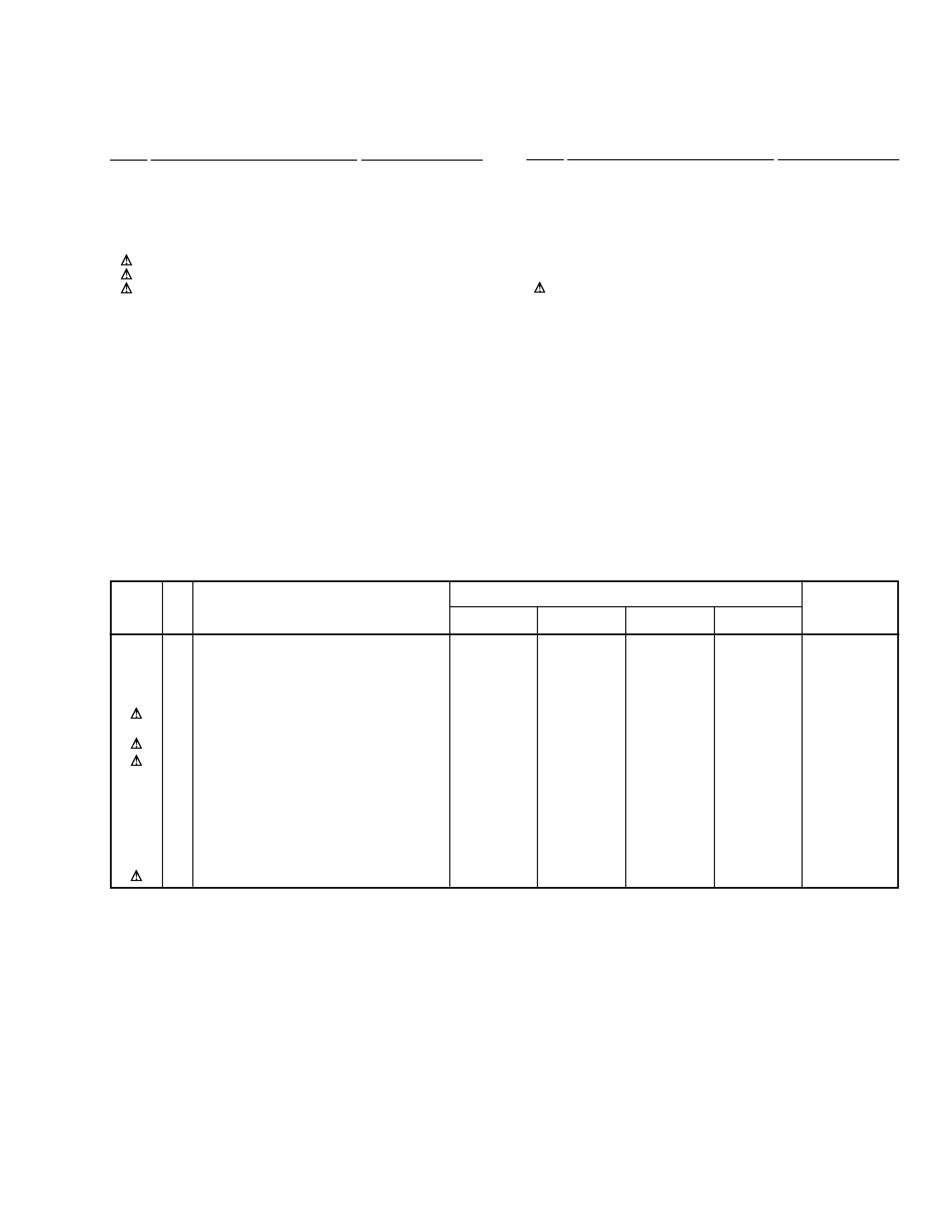
Type
Model
Power Requirement
CT-W208R
KUXJ
AC120V
KCXJ
AC120V
HYXJ
AC220-230V
HVXJ
AC230-240V
THIS MANUAL IS APPLICABLE TO THE FOLLOWING MODEL(S) AND TYPE(S).
STEREO DOUBLE CASSETTE DECK
Remarks
AUTO REVERSE
Auto Tape Selector
Auto Tape Selector
HIGH SPEED COOPY SYSTEM / REC & PLAY
HIGH SPEED COOPY SYSTEM / PLAYBACK
STEREO DOUBLE
CASSETTE DECK
NORMAL
HIGH
POWER
-- OFF _ ON
HIGH SPEED
COPY SYSYEM
MIN
MAX
REC
LEVEL
REV MODE
RELAY/SKIP
COPY I
II
3
DOLBY B-C NR
i¿^<?B
DECK
II
DECK
I
Î
DOLBY NR
OFF
BC
DECK II
MS
MS
+
--
+
--
DECK I
AUTO REVERSE
DECK II
PLAY
-15
-9
-3
-3
0
-0 0
RIGHT
LEFT
COPY
DECK II
DECK I
dB
Y
FWD
REV
PLAY
FWD
REV
REC
LEVEL
2
CT-W208R
1. SAFETY INFORMATION
This service manual is intended for qualified service technicians ; it is not meant for the casual do-it-
yourselfer. Qualified technicians have the necessary test equipment and tools, and have been trained
to properly and safely repair complex products such as those covered by this manual.
Improperly performed repairs can adversely affect the safety and reliability of the product and may
void the warranty. If you are not qualified to perform the repair of this product properly and safely, you
should not risk trying to do so and refer the repair to a qualified service technician.
WARNING
This product contains lead in solder and certain electrical parts contain chemicals which are known to the state of California to cause
cancer, birth defects or other reproductive harm.
Health & Safety Code Section 25249.6 Proposition 65
NOTICE
(FOR CANADIAN MODEL ONLY)
Fuse symbols
(fast operating fuse) and/or
(slow operating fuse) on PCB indicate that replacement parts must
be of identical designation.
REMARQUE
(POUR MODÈLE CANADIEN SEULEMENT)
Les symboles de fusible
(fusible de type rapide) et/ou
(fusible de type lent) sur CCI indiquent que les pièces
de remplacement doivent avoir la même désignation.
ANY MEASUREMENTS NOT WITHIN THE LIMITS
OUTLINED ABOVE ARE INDICATIVE OF A POTENTIAL
SHOCK HAZARD AND MUST BE CORRECTED BEFORE
RETURNING THE APPLIANCE TO THE CUSTOMER.
2. PRODUCT SAFETY NOTICE
Many electrical and mechanical parts in the appliance
have special safety related characteristics. These are
often not evident from visual inspection nor the protection
afforded by them necessarily can be obtained by using
replacement components rated for voltage, wattage, etc.
Replacement parts which have these special safety
characteristics are identified in this Service Manual.
Electrical components having such features are identified
by marking with a
on the schematics and on the parts list
in this Service Manual.
The use of a substitute replacement component which does
not have the same safety characteristics as the PIONEER
recommended replacement one, shown in the parts list in
this Service Manual, may create shock, fire, or other hazards.
Product Safety is continuously under review and new
instructions are issued from time to time. For the latest
information, always consult the current PIONEER Service
Manual. A subscription to, or additional copies of, PIONEER
Service Manual may be obtained at a nominal charge from
PIONEER.
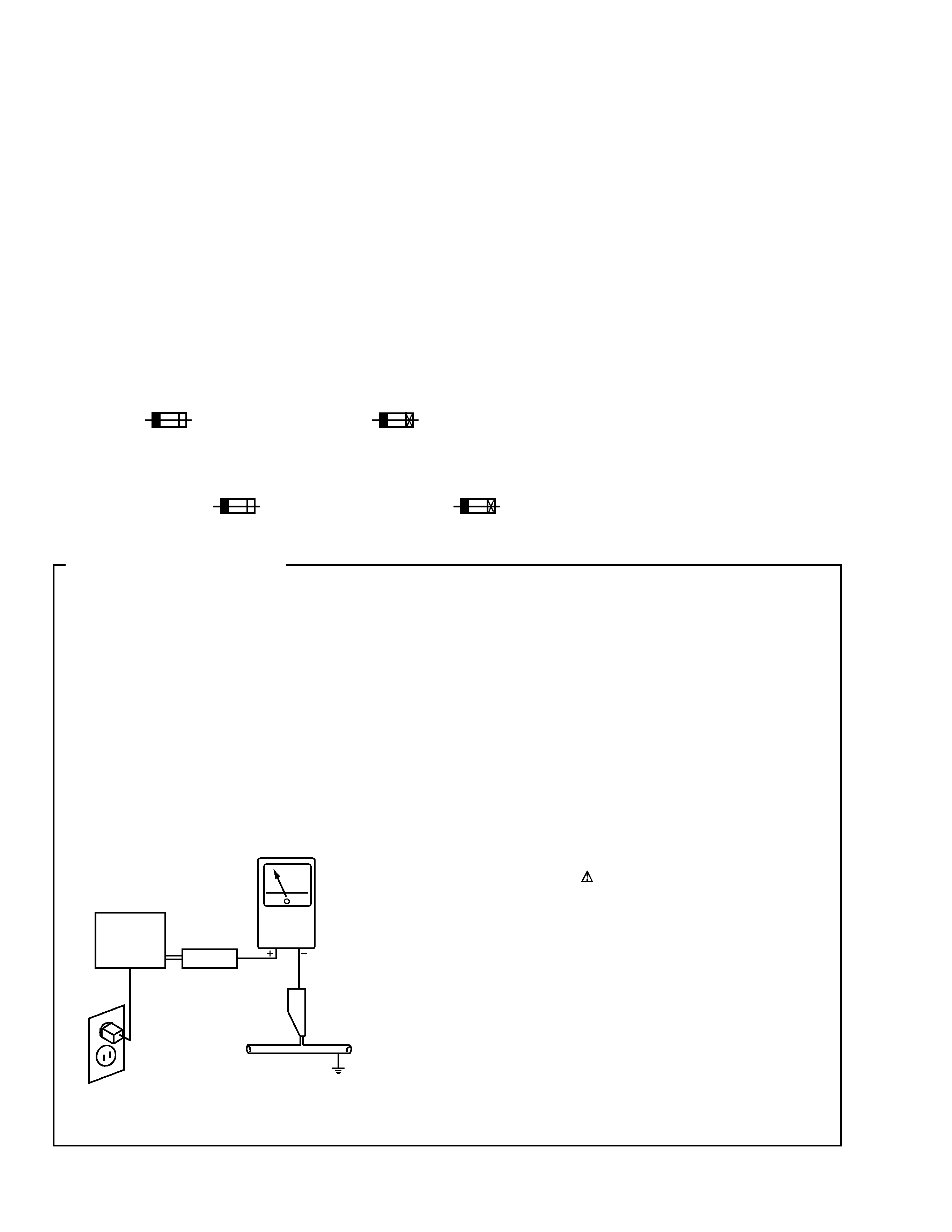
1. SAFETY PRECAUTIONS
The following check should be performed for the
continued protection of the customer and service
technician.
LEAKAGE CURRENT CHECK
Measure leakage current to a known earth ground (water
pipe, conduit, etc.) by connecting a leakage current tester
such as Simpson Model 229-2 or equivalent between the
earth ground and all exposed metal parts of the appliance
(input/output terminals, screwheads, metal overlays, control
shaft, etc.). Plug the AC line cord of the appliance directly
into a 120V AC 60Hz outlet and turn the AC power switch
on. Any current measured must not exceed 0.5mA.
(FOR USA MODEL ONLY)
Leakage
current
tester
Reading should
not be above
0.5mA
Device
under
test
Test all
exposed metal
surfaces
Also test with
plug reversed
(Using AC adapter
plug as required)
Earth
ground
AC Leakage Test
3
CT-W208R
3
Packing Case
RHG1912
RHG1912
RHG1910
RHG1911
7
Operating Instructions (English)
RRB1198
Not used
Not used
RRB1198
8
Operating Instructions
Not used
Not used
RRD1218
Not used
(Spanish/Portuguese/Dutch/Swedish
/German/Italian)
9
Operating Instructions (English/French)
Not used
RRE1179
RRE1179
Not used
NSP
10
Warranty Card
ARY7023
ARY7024
ARY7022
ARY7022
11
Spacer A
Not used
Not used
Not used
RHC1032
12
Polyethylene Bag (115X270X0.05)
Not used
Not used
Not used
Z21-013
13
Spacer B
Not used
Not used
Not used
RHC1033
14
Caution Card
Not used
Not used
Not used
RRN1001
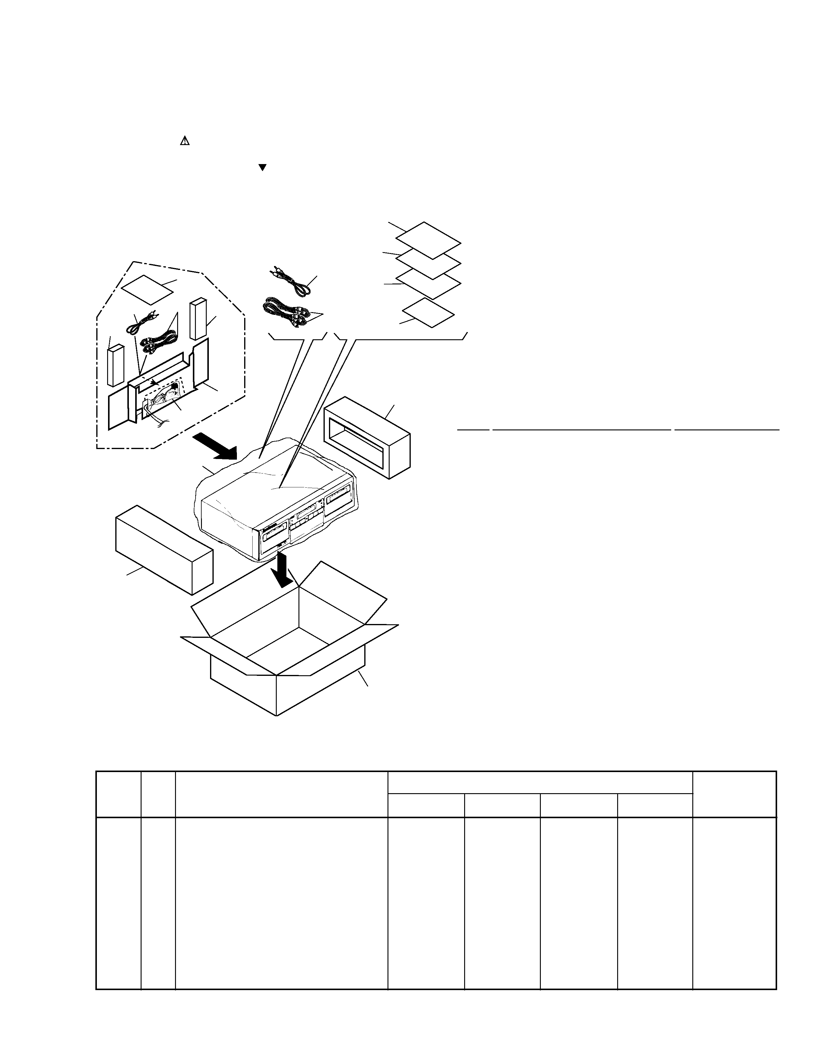
2.1 PACKING
1
Pad L
RHA1115
2
Pad R
RHA1116
3
Packing Case
See Contrast table (2)
4
Mirror Mat Sheet
Z23-007
(750x600x0.5)
5
Control Cable (L=1.0m)
PDE1267
6
Connection cord with Pin-plug
RDE1036
(L=1.0m)
(1) PACKING PARTS LIST
Mark No.
Description
Part No.
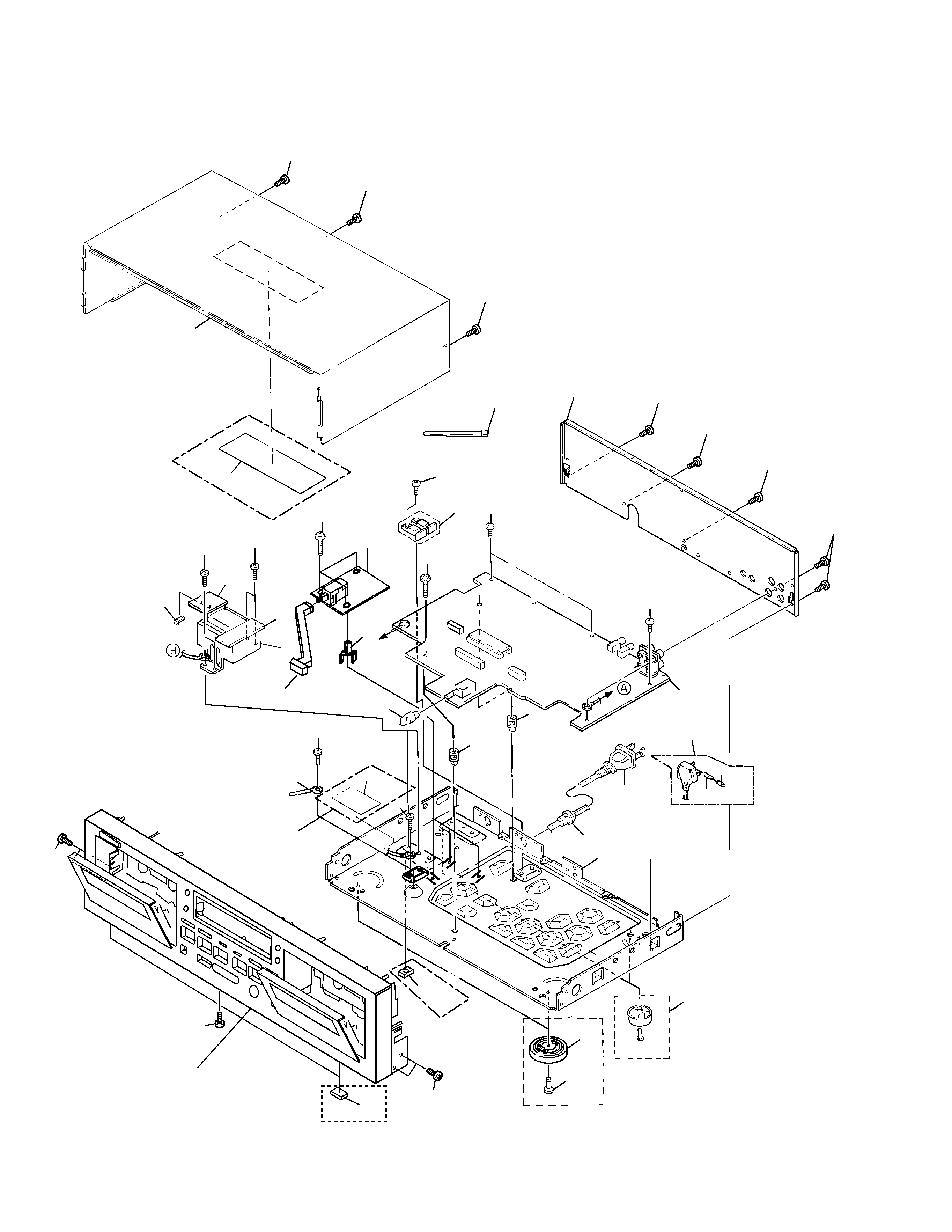
2. EXPLODED VIEWS AND PARTS LIST
NOTES:
· Parts marked by "NSP" are generally unavailable because they are not in our Master Spare Parts List.
· The mark found on some component parts indicates the importance of the safety factor of the part.
Therefore, when replacing, be sure to use parts of identical designation.
· Screws adjacent to mark on the product are used for disassembly.
HVXJ type Only
}
}
3
1
4
2
12
6
7 (KUXJ,
HVXJ types only)
8 (HYXJ
type only)
10
9 (HYXJ,
KCXJ
types only)
14
11
11
5
13
6
5
(2) CONTRAST TABLE
CT-W208R/KUXJ, KCXJ, HYXJ and HVXJ are constructed the same except for the following :
7
Operating Instructions
See Contrast table (2)
(English)
8
Operating Instructions
See Contrast table (2)
(Spanish/Portuguese/Dutch/Swedish
/German/Italian)
9
Operating Instructions
See Contrast table (2)
(English/French)
NSP
10
Warranty Card
See Contrast table (2)
11
Spacer A
See Contrast table (2)
12
Polyethylene Bag
See Contrast table (2)
(115x270x0.05)
13
Spacer B
See Contrast table (2)
14
Caution Card
See Contrast table (2)
Remarks
Part No.
KUXJ type
KCXJ type
HYXJ type
HVXJ type
No.
Mark
Symbol and Description
4
CT-W208R
C
C
24
29
7
HVXJ type Only
Fuse holder
HVXJ and HYXJtypes Only
Except HVXJ and HYXJtypes
14
12
24
2
8
9
4
22
21
17
13
13
24
20
24
6
16
24
24
26
24
19
28
1(1/2)
1(2/2)
10
15
5
7
27
27
27
Refer to " 2.3 FRONT PANEL SECTION".
27
11
23
27
27
27
27
27
27
27
25
18
KUXJ type Only
KUXJ and KCXJ
types Only
HVXJ and HYXJ
types Only
2.2 EXTERIOR
5
CT-W208R
1
MAIN UNIT
RWZ4352
RWZ4352
RWZ4348
RWZ4393
NSP
2
POWER SWITCH UNIT
RWZ4367
RWZ4367
RWZ4365
RWZ4397
NSP
4
Transformer 2 UNIT
RWZ4351
RWZ4351
RWZ4350
RWZ4396
5
Cord Stopper
CM-22C
CM-22C
CM-22B
CM-22B
6
Fuse (FU1, FU2, 1.25A)
REK1076
REK1076
REK1023
REK1023
7
AC Power Cord
PDG1064
PDG1064
PDG1043
PDG1055
8
Power Transformer
RTT1311
RTT1311
RTT1312
RTT1312
11
Rear Panel
RNA2245
RNA2245
RNA2243
RNA2244
12
Rubber Sheet
AEB1111
AEB1111
Not used
Not used
15
Insulator
Not used
Not used
PNW2766
PNW2766
17
Fuse Caution Label
RRW111
RRW111
Not used
Not used
20
65 Label
ARW7050
Not used
Not used
Not used
25
Disc Guard
Not used
Not used
REC1305
REC1305
28
Fuse (T5A) (For AC Power Cord)
Not used
Not used
Not used
PEK1003
(1) EXTERIOR PARTS LIST
Mark No.
Description
Part No.
(2) CONTRAST TABLE
CT-W208R/KUXJ, KCXJ, HYXJ and HVXJ are constructed the same except for the following :
Mark No.
Description
Part No.
1
MAIN UNIT
See Contrast table (2)
NSP
2
POWER SWITCH UNIT
See Contrast table (2)
3
· · · · ·
NSP
4
Transformer 2 UNIT
See Contrast table (2)
5
Cord Stopper
See Contrast table (2)
6
Fuse (FU1, FU2, 1.25A)
See Contrast table (2)
7
AC Power Cord
See Contrast table (2)
8
Power Transformer
See Contrast table (2)
9
PCB Mold
AMR2533
NSP
10
Chassis
RNB1144
11
Rear Panel
See Contrast table (2)
12
Rubber Sheet
See Contrast table (2)
NSP
13
PCB Spacer
PNY404
14
Foot Assy
REC1263
15
Insulator
See Contrast table (2)
16
Balance Knob
RAC1705
17
Fuse Caution Label
See Contrast table (2)
18
Power Button
RAC2221
19
Bonnet
REA1292
20
65 Label
See Contrast table (2)
21
Cord Clamper
RNH1005
NSP
22
Transformer 1 PCB
RNZ3340
NSP
23
Binder
ZCAT18S
24
Screw
BBZ30P060FMC
25
Disc Guard
See Contrast table (2)
26
Screw
IBZ30P180FCC
27
Screw
BBZ30P080FZK
28
Fuse (T5A)
See Contrast table (2)
(For AC Power Cord)
29
Screw
IBZ30P150FCC
Mark
Remarks
Part No.
KUXJ type
KCXJ type
HYXJ type
HVXJ type
Symbol and Description
No.