1
CS-G405-K/Q
Service
Manual
ORDER NO.
PET99004
PIONEER ELECTRONIC CORPORATION 4-1, Meguro 1-Chome, Meguro-ku, Tokyo 153-8654, Japan
PIONEER ELECTRONICS SERVICE, INC. P.O. Box 1760, Long Beach, CA 90801-1760, U.S.A.
PIONEER ELECTRONIC (EUROPE) N.V. Haven 1087, Keetberglaan 1 B-9120 Melsele, Belgium
PIONEER ELECTRONICS ASIACENTRE PTE. LTD. 501 Orchard Road, #10-00, Wheelock Place, Singapore 238880
©PIONEER ELECTRONIC CORPORATION 1998
1998 Printed in U.S.A.
· The grille is attached to the cabinet by catches. Detach it by
pulling the grille towards you.
· The woofer, together with the trim-ring, is attached to the baffle
by 6 screws. To detach the woofer, unfasten those screws and
lift up. To detach it, unfasten those screws. When attaching,
orient its terminal upwards.
· The midrange is attached to the baffle by 4 screws. To detach
it, unfasten those screws. When attaching, orient its terminal
downwards.
· The tweeter is attached to the baffle by 4 screws. To detach it,
unfasten those screws. When attaching it, orient its terminal
downwards.
· The super tweeter is attached to the baffle by 4 screws. To
detach it, unfasten those screws. When attaching it, orient it's
terminal downword.
· The port tube is a press-fit to the baffle. To detach it, first
remove the woofer. Then hit the port tube gently towards you
from the inside of the cabinet. When re-attaching, press-fit it to
the baffle, making sure that the plastic ribs on the port-tube
engage with fresh, undamaged material on the baffle.
HOW TO REASSEMBLE AND
DISASSEMBLE
65S
This service manual is intended for qualified service technicians; it is
not meant for the casual do-it- your selfer. Qualified technicians have
the necessary test equipment and tools, and have been trained to
properly and safely repair complex products such as those covered by
this manual.
Improperly performed repairs can adversely affect the safety and
reliability of the product and may void the warranty. If you are not
qualified to perform the repair of this product properly and safely, you
should not risk trying to do so and refer the repair to a qualified service
technician.
SPEAKER SYSTEM
CS-T7100
2
CS-G405-K/Q
PARTS LIST
NOTES: · Parts marked by "NSP" are generally unavailable because they are not in our Master Spare Parts List.
· The "
"mark found on some component parts indicates the importance of the safety factor of the part.
Therefore, when replacing, be sure to use parts of identical designation.
Mark No. Description
Parts No.
Packing Case
266057
Corner Pad Assy
260846
Corner Pad Assy. Front
233043
Poly Bag
256268
Plastic Grille Assy
266077
Low Frequency Trans
40-13A/XL
Screw for LF Trans
222020
Mid Freq Trans (FP10DP61-51F)
255032
Screw for MF Trans
222011
High Freq Trans (P66AP32-56F)
194709
Screw for HF Trans
222011
Super High Freq Trans (A16ZD)
194516
Screw for SHF Trans
222011
Port Tube (Plastic)
225687
Instruction Manual
266062
Speaker Wire
101717
Mark No. Description
Parts No.
For Packing
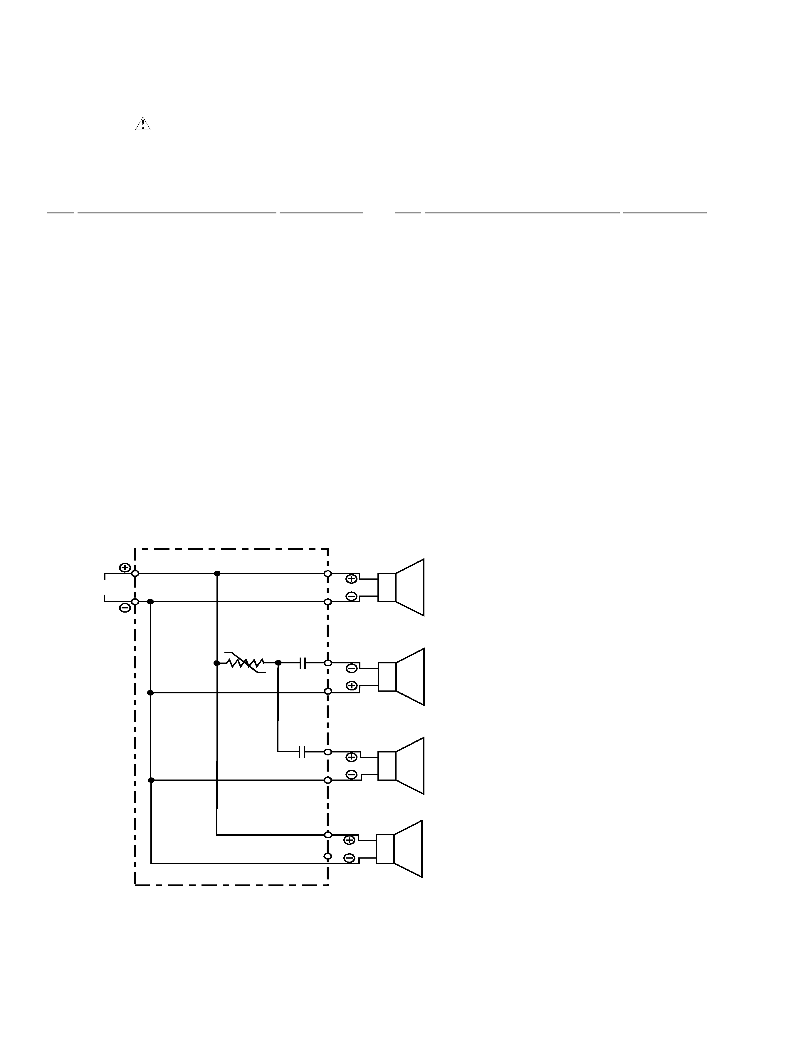
SCHEMATIC DIAGRAM
BLU
WHT
RED
WHT
Woofer
Tweeter
RED
BLK
INPUT
1.0
µ F / 50 V
WHT
GRN
Mid Range
3.3
µ F / 50 V
P. SW 0.75A
BRN
WHT
Super Tweeter