ORDER NO.
CRT2910
PUB. NO.
CRT2910
AUDIO SYSTEM
CD CHANGER
Manufactured for TOYOTA
by PIONEER CORPORATION
VEHICLE
DESTINATION
PRODUCED AFTER
TOYOTA PART No.
ID No.
PIONEER MODEL No.
LEXUS GS430
AMERICA,
August 2002
86270-30210
CDX-M8227ZT/E
LEXUS GS300
EUROPE,
CDX-M8227ZT-91/E
MIDDLE EAST,
SOUTH KOREA,
TAIWAN, CHINA
GS430,300
Service
Manual
2
1
234
12
34
F
E
D
C
B
A
CDX-M8227ZT/E
- CD Player Service Precautions
1. Before disassembling the unit, be sure to turn off the
power. Unplugging and plugging the connectors dur-
ing power-on mode may damage the ICs inside the
unit.
2. To protect the pickup unit from electrostatic dis-
charge during servicing, take an appropriate treat-
ment (shorting pin) by referring to "the DISASSEM-
BLY" on page 49.
3. After replacing the pickup unit, be sure to check the
grating. (See page 34.)
4. The door units CXB9305 and CXB9306 have been
engaged each other tightly. When you have to
replace the door unit CXB9305 or CXB9306, remove
both door units from the Grille to replace them at the
same time.
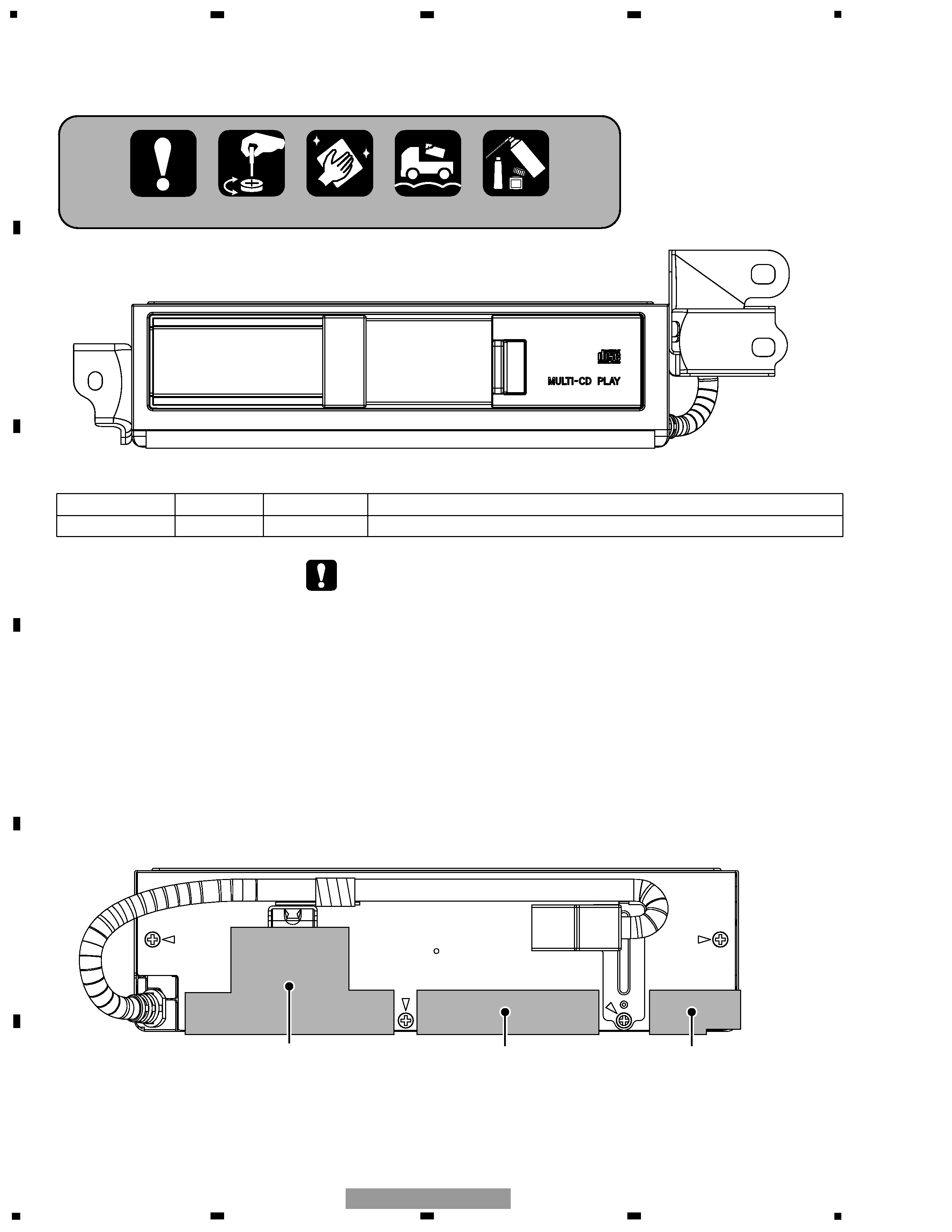
The edges of the case are covered with the following sheets because they may meet and
damage the harness of the vehicle. Be sure to affix the sheets.
*) When you remove the case, basically remove the sheets and affix new ones after finishing service.
Sheet
CNM8001
Sheet
CNM8002
Sheet
CNM8003
- CDX-M8227ZT/E, CDX-M8227ZT-91/E
If you cannot remove the sheets, cut them with a cutter along the grooves of the case and affix
new ones over them.
- This service manual should be used together with the following manual(s):
Model No.
Order No.
Mech. Module Remarks
CX-652
CRT1857
C5
CD Mech. Module:Circuit Description, Mech.Description, Disassembly
For details, refer to "Important symbols for good services".
CDX-M8227ZT/E
3
5
6
7
8
F
E
D
C
B
A
5
6
7
8
CDX-M8227ZT/E
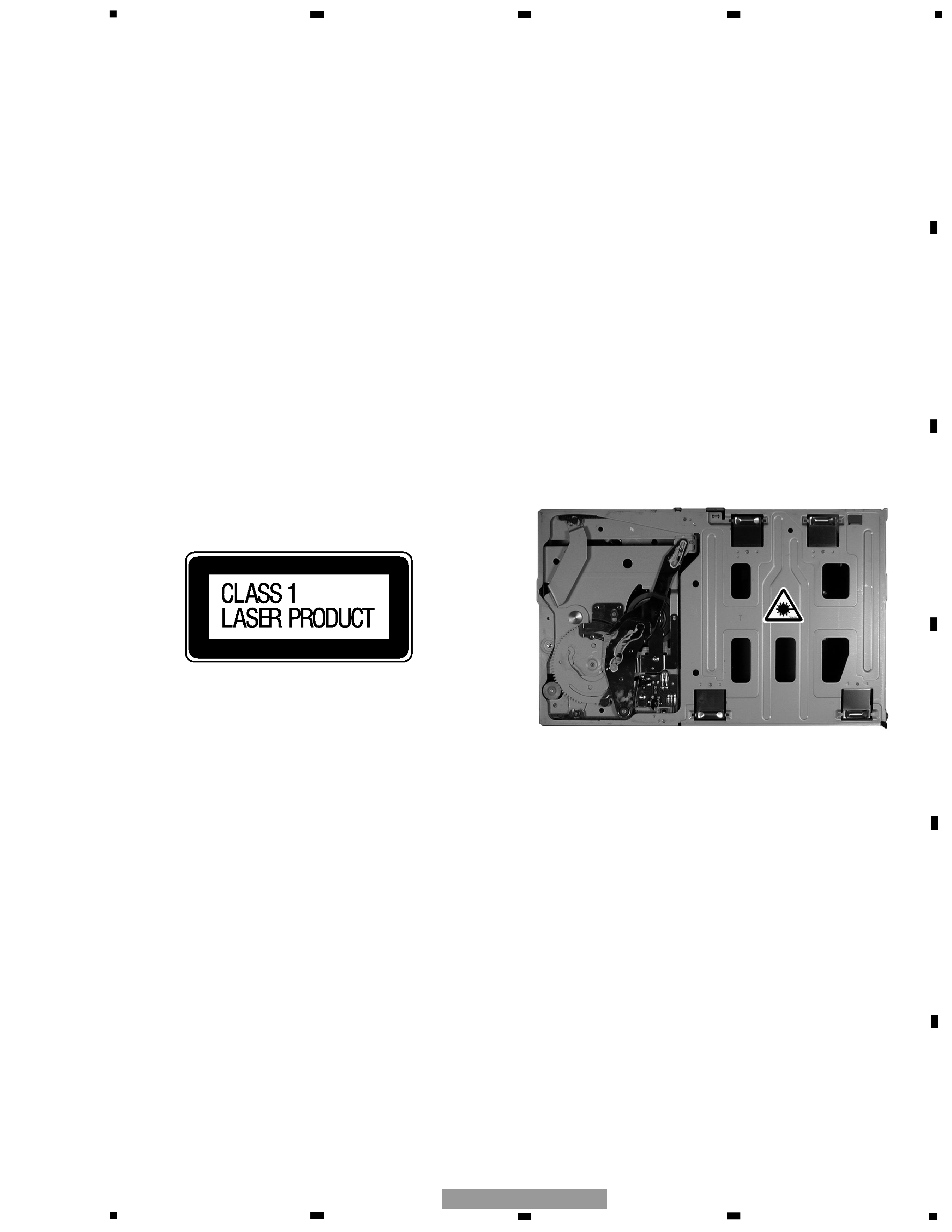
2. A "CLASS 1 LASER PRODUCT" label is affixed to the
bottom of the player
.
3. The triangular label is attached to the mechanism
unit frame.
1. Safety Precautions for those who Service this Unit.
· Follow the adjustment steps (see pages 33 through 39)in the service manual when servicing this unit. When check-
ing or adjusting the emitting power of the laser diode exercise caution in order to get safe, reliable results.
Caution:
1. During repair or tests, minimum distance of 13cm from the focus lens must be kept.
2. During repair or tests, do not view laser beam for 10 seconds or longer.
4. Specifications of Laser Diode
Specifications of laser radiation fields to which human access is possible during service.
Wavelength
=
785 nanometers
Radiant power =
69.7 microwatts(Through a circular aperture stop having a diameter of 80 millimeters)
0.55 microwatts(Through a circular aperture stop having a diameter of 7 millimeters)
SAFETY INFORMATION
This service manual is intended for qualified service technicians; it is not meant for the casual do-it-yourselfer.
Qualified technicians have the necessary test equipment and tools, and have been trained to properly and safely repair
complex products such as those covered by this manual.
Improperly performed repairs can adversely affect the safety and reliability of the product and may void the warranty.
If you are not qualified to perform the repair of this product properly and safely, you should not risk trying to do so
and refer the repair to a qualified service technician.
4
1
234
12
34
F
E
D
C
B
A
CDX-M8227ZT/E
1. SPECIFICATIONS
General
Power source ........................................................................................ 13.2 V DC (10.5 16.0 V allowable)
Grounding system .................................................................................................................. Negative type
Backup current ........................................................................................................................ 1.0 mA or less
Dimensions (No including the brackets) .............................................. 248.2(W) x 66.0(H) x 164.5(D) mm
Weight .................................................................................................................................................. 2.05 kg
CD player
System .............................................................................................................. Compact disc audio system
Usable discs .............................................................................................................................. Compact disc
Signal format ................................................................................................ Sampling frequency: 44.1 kHz
Number of quantization bits: 16; linear
Signal-to-noise ratio ................................................................................................................ 85 dB or more
Dynamic range ........................................................................................................................ 80 dB or more
Distortion .................................................................................................................................. 0.04 % or less
Separation ................................................................................................................................ 65 dB or more
Number of channels ........................................................................................................................ 2 (stereo)
CONTENTS
SAFETY INFORMATION ............................................3
1. SPECIFICATIONS........................................................4
2. EXPLODED VIEWS AND PARTS LIST .......................5
3. BLOCK DIAGRAM AND SCHEMATIC DIAGRAM ...10
4. PCB CONNECTION DIAGRAM ................................20
5. ELECTRICAL PARTS LIST ........................................26
6. ADJUSTMENT..........................................................30
7. GENERAL INFORMATION .......................................49
7.1 DIAGNOSIS ........................................................49
7.1.1 DISASSEMBLY .........................................49
7.1.2 CONNECTOR FUNCTION DESCRIPTION .......51
7.2 IC ........................................................................52
7.3 EXPLANATION ...................................................54
7.3.1 SYSTEM BLOCK DIAGRAM.....................54
7.3.2 OPERATIONAL FLOW CHART .................55
7.4 NOTES ON SERVICING .....................................56
7.4.1 CLEANING ................................................56
7.4.2 FACTORY SETTINGS................................56
8. OPERATIONS............................................................56
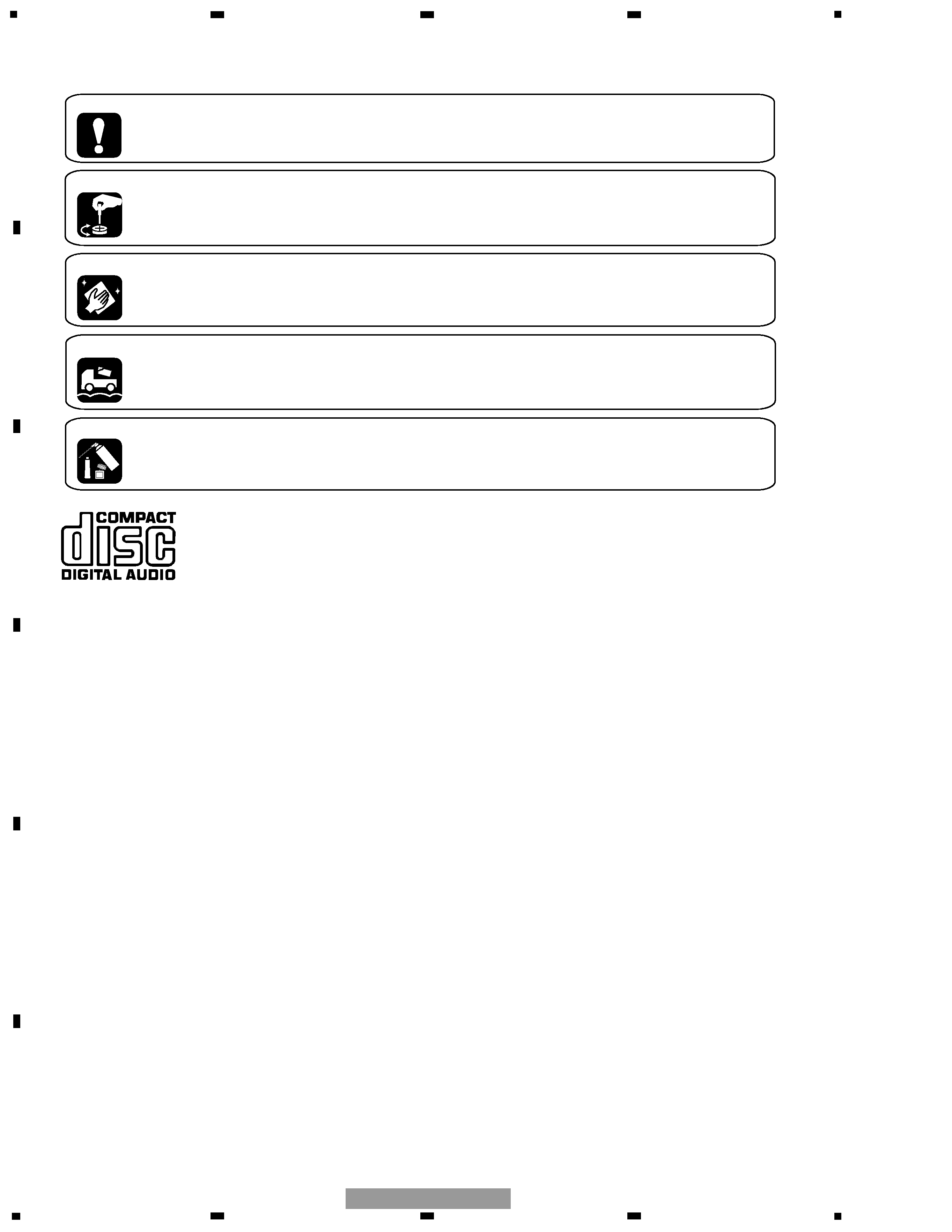
[ Important symbols for good services ]
In this manual, the symbols shown-below indicate that adjustments, settings or cleaning should be made securely.
When you find the procedures bearing any of the symbols, be sure to fulfill them:
2. Adjustments
To keep the original performances of the product, optimum adjustments or specification confirmation is indispensable.
In accordance with the procedures or instructions described in this manual, adjustments should be performed.
3. Cleaning
For optical pickups, tape-deck heads, lenses and mirrors used in projection monitors, and other parts requiring cleaning,
proper cleaning should be performed to restore their performances.
5. Lubricants, glues, and replacement parts
Appropriately applying grease or glue can maintain the product performances. But improper lubrication or applying
glue may lead to failures or troubles in the product. By following the instructions in this manual, be sure to apply the
prescribed grease or glue to proper portions by the appropriate amount.For replacement parts or tools, the prescribed
ones should be used.
4. Shipping mode and shipping screws
To protect the product from damages or failures that may be caused during transit, the shipping mode should be set or
the shipping screws should be installed before shipping out in accordance with this manual, if necessary.
1. Product safety
You should conform to the regulations governing the product (safety, radio and noise, and other regulations), and
should keep the safety during servicing by following the safety instructions described in this manual.
5
5
6
7
8
F
E
D
C
B
A
5
6
7
8
CDX-M8227ZT/E
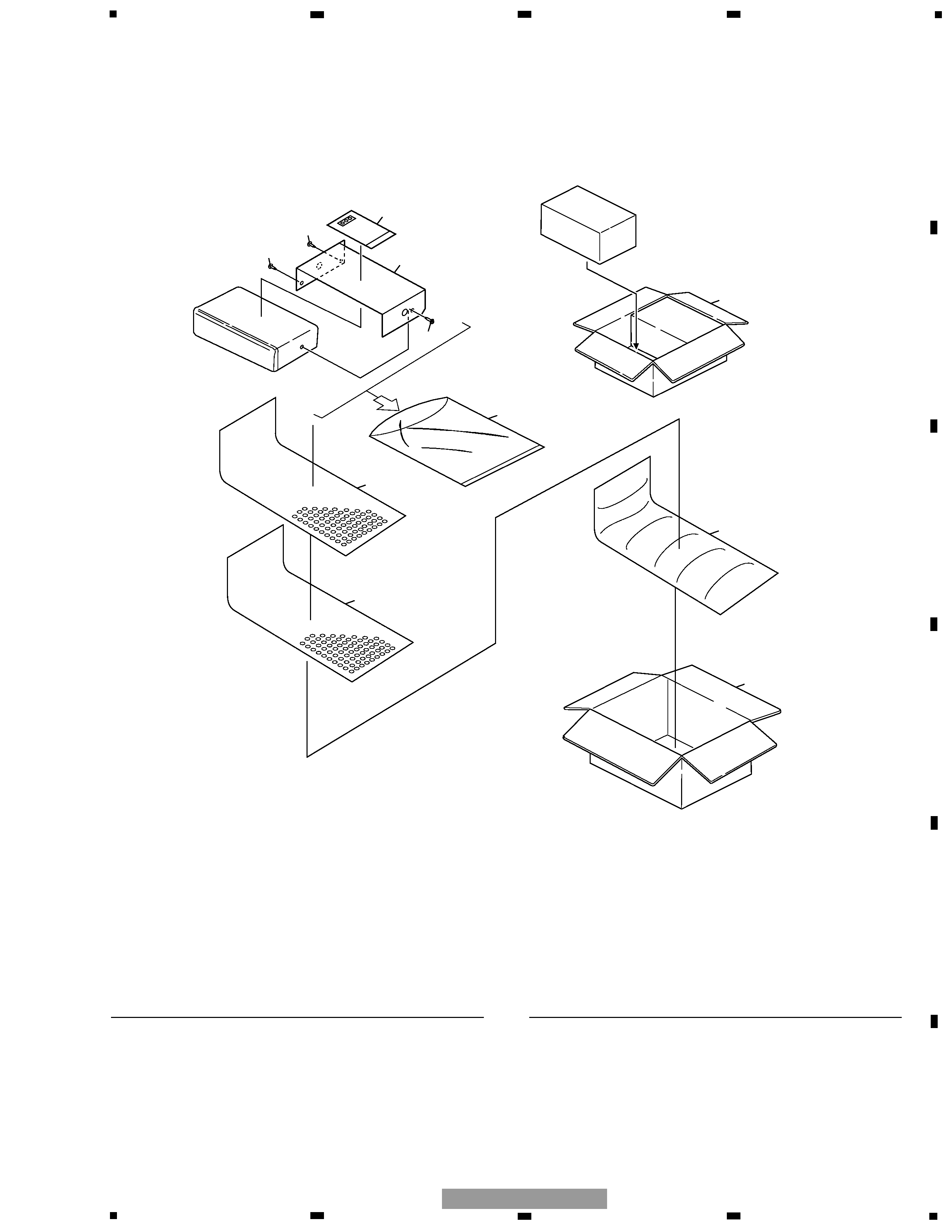
NOTE:
- Parts marked by "*" are generally unavailable because they are not in our Master Spare Parts List.
- Screws adjacent to
mark on the product are used for disassembly.
- For the applying amount of lubricants or glue, follow the instructions in this manual.
( In the case of no amount instructions, apply as you think it appropriate.)
1-1 Polyethylene Bag
CEG1229
1-2 Seal
CNM7435
*
2 Caution Card
CRP1246
3 Screw
CBA1352
4 Polyethylene Bag
CEG1174
5 Cover
CEG1045
*
6 Air Cushioned Bag
CHW1945
7 Carton
CHG4796
8 Contain Box
CHL4826
- PACKING SECTION PARTS LIST
Mark No. Description
Part No.
Mark No. Description
Part No.
1
2
3
3
3
4
5
5
6
7
8
2. EXPLODED VIEWS AND PARTS LIST
2.1 PACKING (CDX-M8227ZT-91/E)